
Looking for crucial electronic engineering questions and answers? Check out our blog on AKTU’s Unit 5: Electronic Instrumentation. Get useful exam preparation ideas and methods to help you ace your examinations!
Dudes 🤔.. You want more useful details regarding this subject. Please keep in mind this as well.

Important Questions For Electronic Engineering:
*Unit-01     *Unit-02
*Unit-03    *Unit-04
*Unit-05    *Short-Q/Ans
*Question-Paper with solution 21-22
Q1. Explain the basic principle of digital voltmeter with the help of block diagram. What are the characteristics of DVM ?
Ans. Digital Voltmeter :
- 1. The digital voltmeter (DVM) is a tool for indication. DVM is mostly used to measure the voltage between two locations. It shows discrete numerals for either DC or AC voltage.
- 2. It is a helpful laboratory tool with a variety of uses. Additionally, it is a valuable component of digital instrumentation systems. In systems for processing data, the DVM is frequently utilised.
- 3. In order to prevent it from consuming any current from the circuit, an ideal voltmeter has an infinitely high input resistance.
- 4. Think about a metre with a 1000 Ω low input resistance. Because the metre shunts the resistance, it is unable to provide a correct reading for the voltage across a resistance of the same magnitude.
- 5. As a result, it’s crucial to calculate the ohms per volt loading impact of a voltmeter.
- 6. The block diagram of a digital voltmeter is shown in Fig. It has three stages :
- a. Signal preparation,
- b. Analog to digital conversion, and
- c. Display unit.
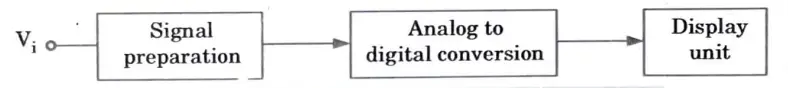
- 7. The signal preparation stage, also known as the input circuit, changes the signal’s amplitude in accordance with the needs and guards against loading the source.
- 8. Here, the big incoming signal is attenuated using a resistive attenuator, and the small incoming signal is amplified to observable levels using an amplifier.
- 9. In essence, digital voltmeters are analogue to digital converters with digital displays that show the voltage being measured.
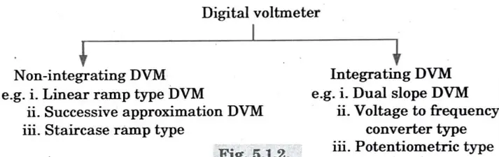
- 10. Digital voltmeter can be categorized as follows :
General characteristics :
- 1. Discrete numbers representing the measurement of OC or AC voltage are shown on the digital voltmeter (DVM).
- 2. This is beneficial in many applications since it decreases interpolation and human reading errors, speeds up reading, and produces output in digital format.
- 3. DVM has following typical operating and performance features :
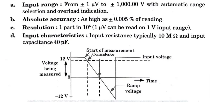
Q2. Explain with the help of neat diagram, working and characteristics curve of ramp type digital voltmeter.
Ans.
- 1. The operation of a ramp type DVM is based on measuring how long it takes a linear ramp voltage to increase or fall from the level of the input voltage to zero volts, respectively.
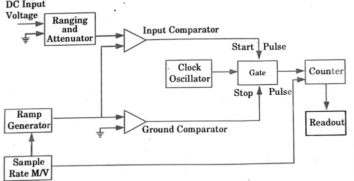
- 2. A ramp voltage is started at the beginning of the measurement cycle; this voltage may be positive going or negative going. The input voltage is compared to the downward ramp (unknown).
- 3. The comparator circuit emits a pulse that opens a gate at the precise moment the ramp voltage equals the unknown voltage. In Fig., this gate is depicted.
- 4. When the ramp voltage finally hits zero volts (or ground potential), a second comparator provides an output pulse that closes the gate.
- 5. A number of decade counting units (DCUs) track the number of clock pulses that have passed through the gate after they are generated by an oscillator.
- 6. The input voltage’s magnitude is indicated by a decimal number that is shown via indicator tubes connected to the DCUs.
Characteristic curve :

Q3. What is CRO? Explain its basic principle.
Ans.
- 1. An electrical tool called a Cathode Ray Oscilloscope (CRO) provides a visual representation of a signal waveform.
- 2. It is frequently employed in laboratory work as well as for troubleshooting radio and television receivers.
- 3. It can also be used for measuring voltage, frequency and phase shift.
Basic principle:
- 1. In a CRO, electrons are accelerated to a high speed and focused on a fluorescent screen as they are emitted from a cathode.
- 2. Where the electron beam collides with the screen, a visible spot is created.
- 3. Electrons can be made to act as an electrical pencil of light that produces a spot of light wherever it strikes by deflecting the electron beam over the screen in response to an electrical signal.
- 4. Due to their extremely low mass, electrons react almost instantly to electrical signals and can almost always trace even the fastest electrical fluctuations.
- 5..A cathode ray tube and the accompanying power supplies are what make up a CRO.
Q4. With the help of neat block diagram, explain the working of a CRO.
Ans.
- 1.The cathode ray oscilloscope is a very useful and adaptable laboratory tool for measuring voltage, current, power, and frequency as well as for examining the waveforms of alternating currents and voltages.
- 2. The block diagram ofCRO is shown in Fig.
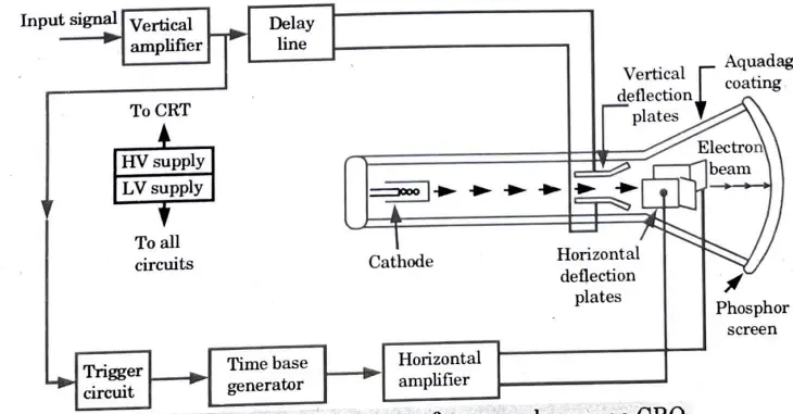
Block Diagram :
- 1. The CRO employs a cathode ray tube (CRT).
- 2. It produces an electron beam, accelerates it to a high speed, deflects it to produce a picture, and then eventually makes the electron beam visible on a phosphor screen.
- 3. High voltage, of the order of a few thousand volts, is needed for the CRT to accelerate the beam while low voltage supply is needed for heating the electron gun for beam generation.
- 4. Between the electron gun and the screen are deflection plates that allow the beam to be bent based on the input signal.
- 5. Electron beam strikes the screen and creates a visible spot.
- 6. On the screen, this point is refracted at a constant time-dependent rate in the X direction.
- 7. Through the vertical amplifier, which elevates the input signal’s potential to a level that will allow for usable electron beam deflection, the input signal is delivered to the vertical deflection plates.
- 8. Now electron beam deflects in 2 directions, horizontal on X-axis and vertical on Y-axis.
Function of each block :
1. CRT : This cathode ray tube produces electrons, which impact an internal phosphor screen to provide a visual display of the signal.
2. Vertical amplifier : Signals in the vertical part are amplified using this broad band amplifier.
3. Delay line : In the vertical parts, it is utilized to slightly delay the signal.
4. Time base : It is utilized to provide the sawtooth voltage needed to deflect the horizontal section of the beam.
5. Horizontal amplifier : Before being applied to horizontal deflection plates, this is utilized to enhance the sawtooth voltage.
6. Trigger circuit : This is used to convert the incoming signal into trigger pulses so that the input signal and the sweep frequency can be synchronized.
7. Power supply :
- a. A negative High Voltage (HV) supply and a positive Low Voltage (LV) supply are the two power sources.
- b. In the CRO, there are two voltages produced. The range of the positive voltage supply is + 300 to 400 V. The low-voltage supply ranges from -1000 to – 1500 V.
- c. This voltage is passed through a bleeder resistor at a few mA.
- d. For controls over intensity, focus, and placement, the bleeder resistor provides the intermediate voltages.
Q5. Explain digital storage oscilloscope with block diagram.
Ans.
- 1. The input signal is digitised by a digital oscilloscope, making all subsequent signals digital.
- 2. Storage takes place in electronic digital memory, which is shown on a traditional CRT.
- 3. Fig. shows a block diagram of a basic digital storage oscilloscope.
- 4. The input signal is converted to digital form and stored in memory. It can be analysed in this state to provide a range of various types of information.
- 5. The data from memory is reconverted into analogue form in order to view the display on the CRT.
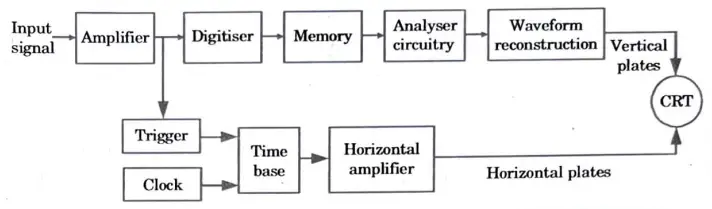
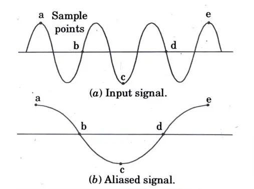
- 6. A sample of the input waveform is talced at regular intervals to digitize it.
- 7. According to sampling theory, the sampling rate must be at least twice as rapid as the input signal’s maximum frequency in order to prevent information loss. Aliasing will happen as a result if this is not done, as demonstrated in Fig.
- 8. The digitiser, an analogue to digital converter, must have a quick conversion rate due to the requirement for a high sampling rate.·
- 9. Costly flash analogue to digital converters are typically needed for this, and their resolution degrades as sampling rates rise.
- 10. This is the reason why an analogue to digital converter typically imposes a limit on the bandwidth and resolution of a digital oscilloscope.
Q6. Give the comparison of DSO with analog oscilloscope .
Ans.
| S.No. | Analog storage oscilloscope | Digital storage oscilloscope |
| 1. | Its writing speed and bandwidth are higher. | Its writing speed and bandwidth are lower. |
| 2. | CRT used in it, is costlier. | CRT used in it, is cheaper. |
| 3. | Capability of storage time is limited. | Capability of storage time is infinite. |
| 4. | Time base signal in analog oscilloscope is generated by ramp circuit. | ‘Time base signal in digital storage oscilloscope is generated by a crystal clock. |
| 5. | It cannot work in look back mode. | It can work in look back mode. |
| 6. | Accuracy is less. | Accuracy is high. |
| 7. | Analog oscilloscope collects data after it is has been triggered. It has slower writing and bandwidth. | Data collection by DSO is constant, and trigger indicates when to stop. |

Electronic Engineering Quantum PDF, Syllabus, Important Questions
| Label | Link |
|---|---|
| Subject Syllabus | Syllabus |
| Short Questions | Short-question |
| Important Unit-1 | Unit-1 |
| Important Unit-2 | Unit-2 |
| Important Unit-3 | Unit-3 |
| Important Unit-4 | Unit-4 |
| Important Unit-5 | Unit-5 |
| Question paper – 2021-22 | 2021-22 |
Electronic Engineering Quantum PDF | AKTU Quantum PDF:
| Quantum Series | Links |
| Quantum -2022-23 | 2022-23 |
AKTU Important Links | Btech Syllabus
| Link Name | Links |
|---|---|
| Btech AKTU Circulars | Links |
| Btech AKTU Syllabus | Links |
| Btech AKTU Student Dashboard | Student Dashboard |
| AKTU RESULT (One VIew) | Student Result |