This blog offers a thorough answer to the AKTU B.Tech. Engineering Mechanics previous year question paper for the year of study 2021-2022. It is a must-have resource for students studying for upcoming examinations.
Dudes 🤔.. You want more useful details regarding this subject. Please keep in mind this as well.

Important Questions For Engineering Mechanics:
*Unit-01     *Unit-02
*Unit-03    *Unit-04
*Unit-05    *Short-Q/Ans
*Question-Paper with solution 21-22
Section A : Short Question in Engineering Mechanics
a. Write down the different types of supports and loading system.
Ans. Types of Supports : Following are the different types of support:
- i. Simple support or knife edge support,
- ii. Roller support,
- iii. Pin joint or hinged support,
- iv. Smooth surface support, and
- v. Fixed or built-in support.
Loading Systems: Following are the different types of loads to which the beam can be subjected:
- i. Concentrated or point load,
- ii. Uniformly distributed load (UDL), and
- iii. Uniformly varying load (UVL).
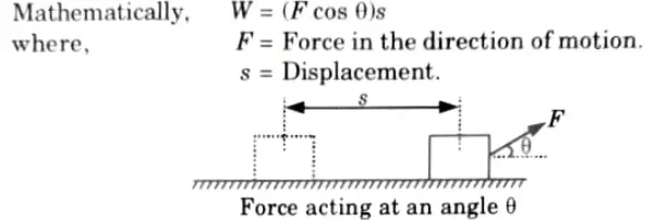
b. Define work and power. Write the mathematical relation and SI unit .
Ans. Work Done : In general, work is defined as the result of the displacement and the component of the force acting in the direction of motion. In general, work is defined as the result of the displacement and the component of the force acting in the direction of motion.
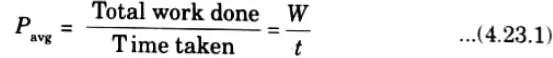
Power:
1. The rate at which work is completed is referred to as power. A machine’s capacity to perform work is typically stated as its rated power.
2. If W is the total work done in a time interval t, then average power is given by,
3. The instantaneous power, i.e., power at a particular instant of time is given by,
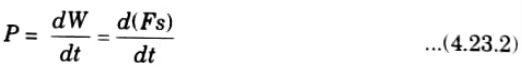
4. The force can be assumed to be constant over this infinitesimally small time interval dt. Hence, we can write the above expression as:
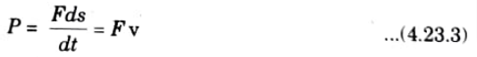
5. The unit of power in the SI system of units is the joule per second (J/sec), often known as the watt (W).
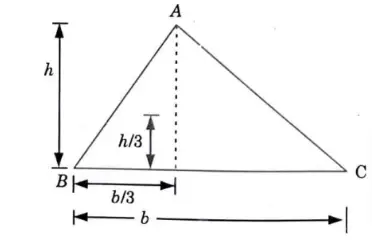
c. Define the center of mass and write down the coordinates of center of gravity of triangle.
Ans. Centre of Mass : the location where a body’s complete mass is thought to be concentrated. In any position, a body’s centre of mass remains constant.
Coordinates of Centre of Gravity of Triangle : Consider the triangle ABC of base width ‘b’ and height ‘h’ as shown in Fig. 1. The coordinate of centroid of a triangle is (b/3, h/3).
d. What is the difference between collinear and concurrent forces?
Ans. Difference between Collinear and Concurrent Forces :
| S. No. | Collinear Force | Concurrent Force |
| 1. | Each force’s path of action follows the same path. | All forces are in the same plane and their lines of action all intersect at this same place. |
| 2. | Forces on a rope in a tug of war. | Forces on a rod resting against a wall. |
e. Write down D’Alembert’s principle.
Ans. According to D’Alembert’s principle, the system’s net external force and the ensuing inertia force are in a condition of equilibrium.
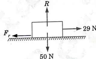
f. A body of weight 50 N placed on a horizontal surface is just moved by a force of 29 N . Find the frictional force and normal reaction.
Ans. Given : Body weight, W = 50 N; Force, F = 29 N
To Find : Frictional force t Normal reaction.
Consider the equilibrium of body:
Normal reaction, R = Weight of body= 50 N
Force of friction = Applied force = 29 N
g. What do you understand by point of contraflexure ?
Ans. The part of the beam where the bending moment is zero or changes its sign is represented by the point of contraflexure.
h. Discuss the merits and demerits of friction.
Ans. Merits of Friction :
- 1. We may move freely because of friction.
- 2. Leaning the ladder up against a wall is helpful.
- 3. Vehicle breaks function as a result of friction.
Demerits of Friction :
- 1. Heat created by friction makes things wear out.
- 2. Sparks, overheating, and machine failure are some effects of friction.
- 3. Friction slows down motion.
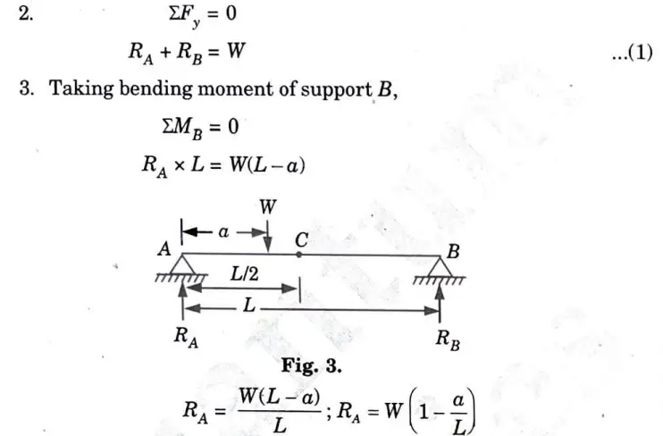
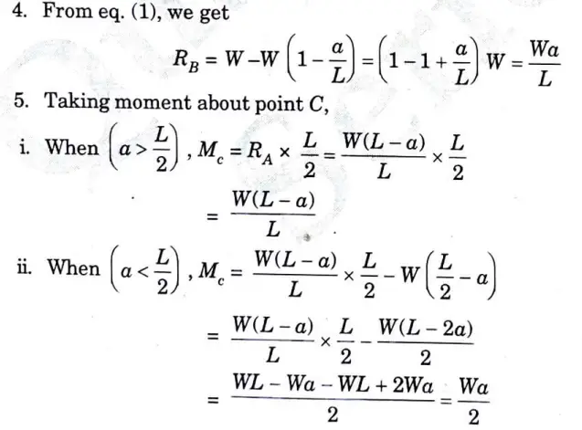
i. Calculate the bending moment at centre of a simply supported beam carrying a point load.
Ans. Given : Simply supported beam, and concentrated load.
To Find : Bending moment at centre of beam.
1. Consider a simply supported beam of span L carriage a concentrated load at a distance ‘a’ from left end.
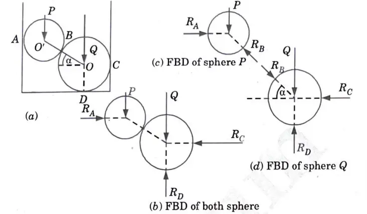
j. Two spheres of weight P and Q rest inside a hollow cylinder ;h1ch is resting on a horizontal plane. Draw the free body diagram of both the spheres, together and separately.
Ans.
Section B: Important Long Question in Engineering Mechanics
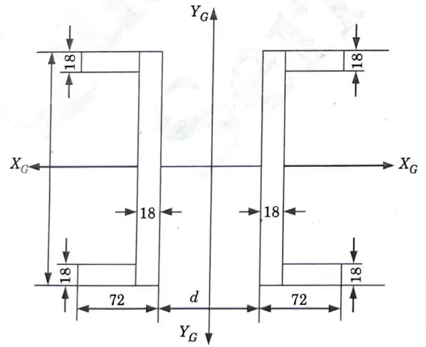
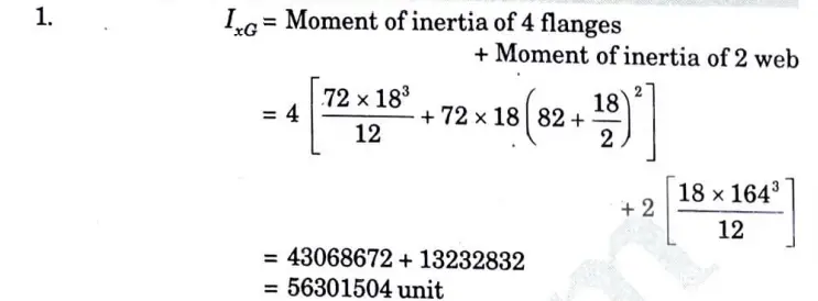
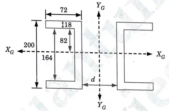
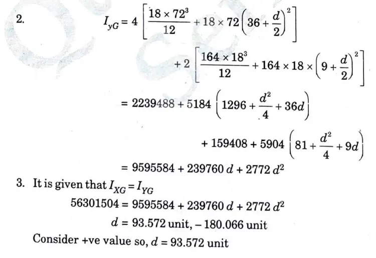
a. Two channels are kept as shown in given Fig. 5, at a distance d between them to form the cross section of a column. Find the value of the distance d if the centroidal moment of inertia Ix and Iy of the area are equal.
Ans.
Given : Distance between two channels = d and Fig. 5.
To Find : Distance d for Ixx and Iyy is equal.
b. A uniform rod 4 m long weighing 400 N is rigidly connected to the centre of a cylinder of mass 30 kg, as shown in given Fig. 7. The diameter of cylinder is 2 m. Find the linear acceleration of block weighing 2000 N connected to the cylinder by an inextensible string.
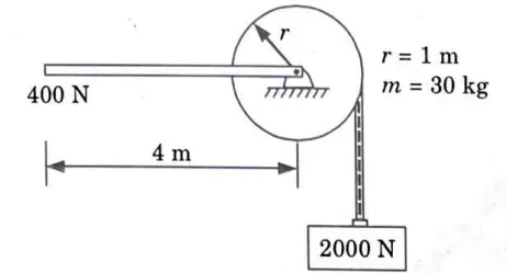
Ans. Given: Length Of Rod, l = 4m, Weight Rod, W = 400 N, Mass of cylinder, m = 30 kg, Diameter of cylinder, d = 2m, Weight of block, wb = 2000 N.
To Find: Linear acceleration of block.
1. We know that, linear ·acceleration is given by,
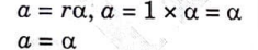
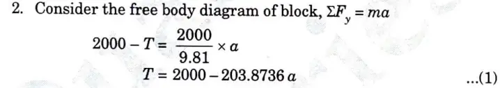
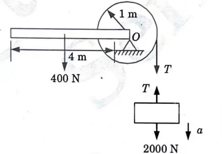
3. Taking moment about point O,
4. From eq. (1) and (2), we get a = 2.75 rn/sec2
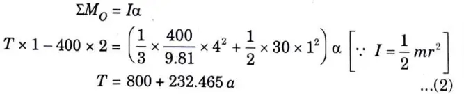
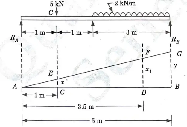
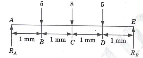
c. Explain the principle of virtual work. A simply supported beam AB of span 5 m is loaded as shown in given Fig. 9. Using the principle of virtual work, find the reactions at A and B.
Ans. Principle of Virtual Work: The resultant force exerted on the particle or rigid body must be zero for it to maintain equilibrium in the displaced position as well. As a result, we claim that the effort put into creating this virtual displacement was similarly zero. This is referred to as the virtual work principle.
Numerical:
Given: Span of beam, L = 5 m, Concentrated load, W = 5 kN, UDL intensity, w = 2 kN/m, Span of UDL = 3 m.
To Find: Reaction at A and B using principle of virtual work.
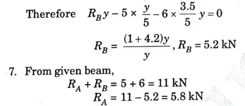
1. Let us assume the beam.to be hingedatA. Now consider an upward virtual displacement (y) of the beam atB. This is due to reaction at B acting upward as shown in Fig. 10. Let x and x1 be the upward virtual displacement of beam at C and D respectively.
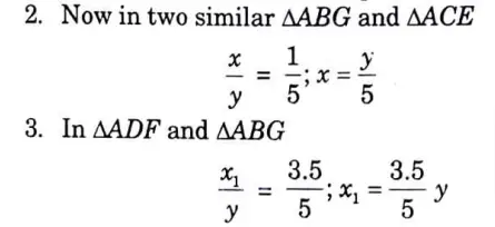
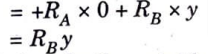
4. Total virtual work done by the two reactions RA and RB
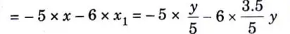
5. And virtual work done by the point load and UDL
6. We know that from the principle of virtual work, that algebraic sum of the virtual work done is zero.
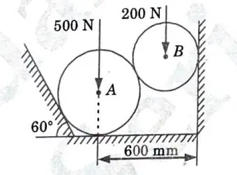
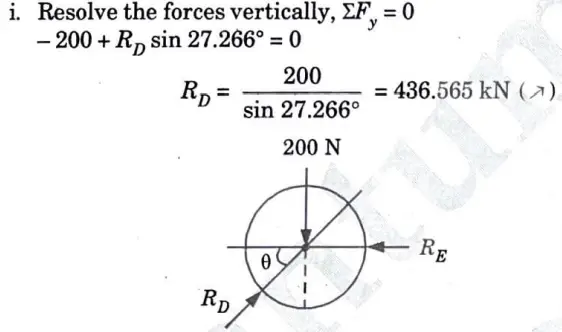
d.State and prove Lami’s theorem. Two spheres, A and B, are resting in a smooth through as shown in given Fig. 11. Draw the free body diagrams of A and B showing all the forces acting on them, both in magnitude and direction. Radius of spheres A and B are 250 mm and 200 mm, respectively.
Ans. Lami’s Theorem: Lami’s theorem states that if three forces acting at a point are in equilibrium, then each force will be proportional to the sine of the angle between the other two forces.
Numerical:
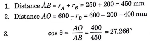
Given : Radius of sphere A, rA = 250 mm, Radius of sphere B, rB = 200 mm and Fig. 11.
To Find : Magnitude and direction of all forces.
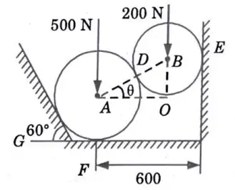
4. Consider the Equilibrium of Sphere (B) :
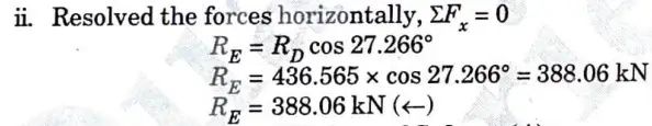
5. Consider the Equilibrium of Sphere(A) :
e. Differentiate between rectilinear and curvilinear motion. Also derive the expression for the horizontal range, time of flight and maximum height of a projectile with initial velocity ‘u’ and inclined at an angle ‘α’ with the horizontal.
Ans. Difference:
| S. No. | Rectilinear Motion | Curvilinear Motion |
| 1. | Rectilinear motion is the term used to describe a body’s motion in a straight line. | Curvilinear motion is the term used to describe how a body moves along a curved path. |
| 2. | It is also known as one dimensional motion. | It is also known as multi dimensional motion. |
| 3. | Equation of motion for rectilinear motions are given by,v = u + ats = ut + 1/2 at2v2 = 𝛍2 + 2as | Equations of motion for curvilinear motion are given by,w = w0 + 𝛂t𝚹 = w0t + 1/2 𝛂t2w2 = w02 = 2𝛂𝚹 |
| 4. | Example: A ball thrown vertically upward, a car traveling on a straight road. | Example: A golf ball hit from the ground, a motion traveling on a curved road. |
Derivation:
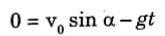
i. Time Taken to Reach Maximum Height and Time of Flight:
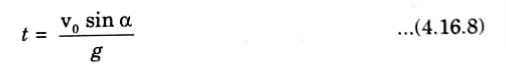
1. When the particle reaches the maximum height, we know that the vertical component of velocity i.e., vy is zero. Therefore, from the eq. (4.16.5), we have
2. Hence, the time taken to reach the maximum height is,
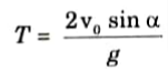
3. Since the time of ascent is equal to the time of descent, the total time taken for the projectile to return to the same level of projection is,
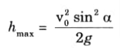
ii. Maximum Height Reached:
1 Substituting the value of time of ascent in the eq. (4.16.7), we get
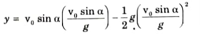
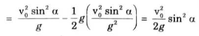
2. Hence, the maximum height reached is,
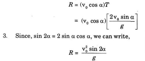
iii. Range:
1. Range is the measurement of the horizontal separation between the projectile’s point of projection and its point of return to the same level of projection.
2. Hence, range is obtained by substituting the value of total time of fight in the eq. (4.16.3),
Section-C : Important Long Question AKTU Notes Q3-Q7
a. A ladder of length 4 m weighing 200 N is placed against a vertical wall, as shown in given Fig. 15. The coefficient of friction between the wall and the ladder is 0.2 and that between the ladder and the floor is 0.3. The ladder in addition to its own weight has to support a man weighing 600 N at a distance of 3 m from A. Calculate the minimum horizontal force to be applied at A to prevent slipping.
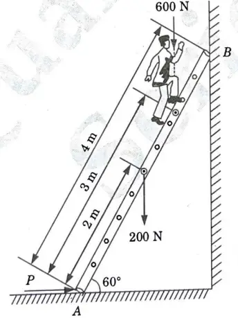
Ans. Given: Length of ladder= 4 m, Weight of ladder = 200 N, Coefficient of friction between wall. and ladder = 0.2, Coefficient of friction between ladder and floor = 0.3, Weight of man= 600 N
To Find: Minimum horizontal force to be applied to prevent slipping.
1. The free body diagram of the ladder is as shown in Fig. 16.
2. Taking moment about point A,
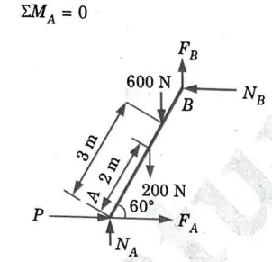
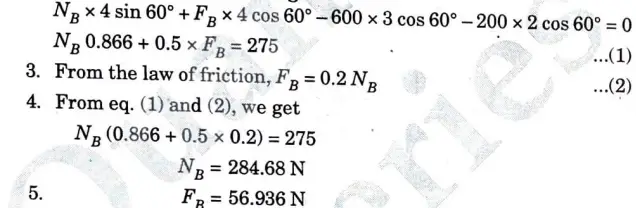
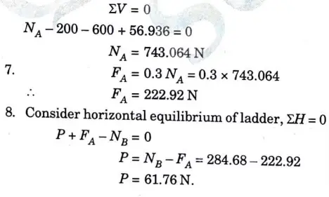
6. Consider vertical equilibrium of ladder,
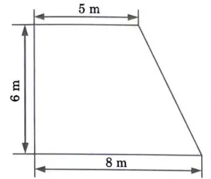
b.Define the centre of gravity and centroid. Find the centroid of the shaded area in given Fig. 17.
Ans. Centre of Gravity : It is the location where the entire body’s weight acts. In any position a body can take, there is only one centre of gravity.
Centroid : The centroid of an area is the location where the entire area of a plane figure such as a triangle, rectangle, circle, etc. is thought to be concentrated.
Numerical:
Given: Fig.17.
To Find : Centroid of shaded area.
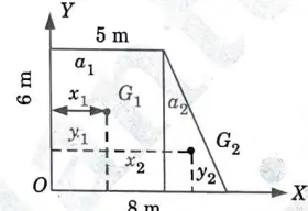
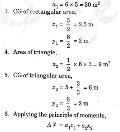
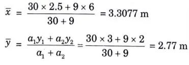
1. Taken O is origin.
2. Area of rectangle,
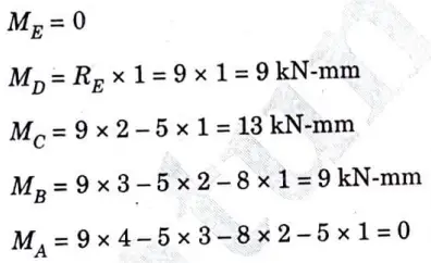
4a. Draw the SF and BM diagram for the simply supported beam loaded as shown in given Fig. 19.
Ans.

1. Loading on beam is symmetrical so,
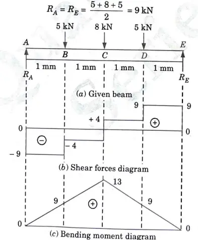
2. Shear force calculation :
3. Calculation of bending moment:
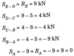
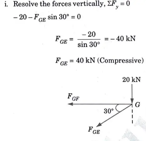
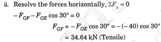
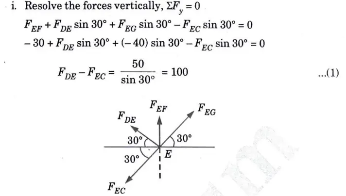
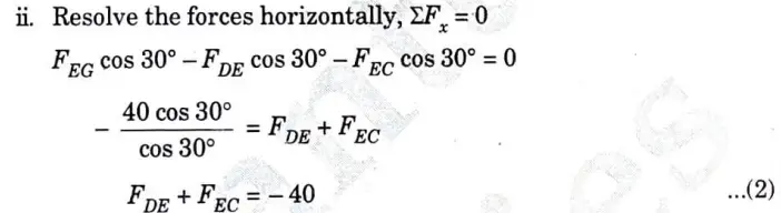
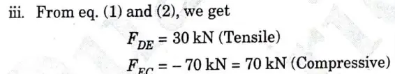
4b.Find the forces in the members DF, DE, CE andEF by method of joints only for the pin jointed frame shown in given Fig. 21.
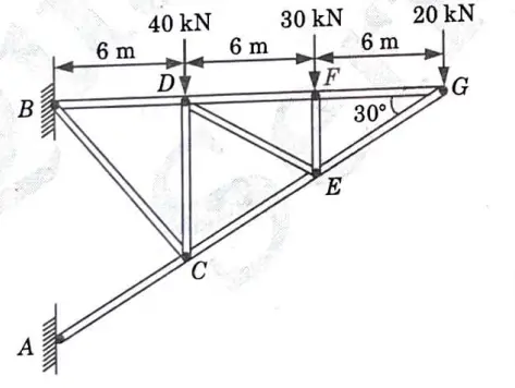
Ans. Given : Fig. 21.
To Find : Force in member DE, DF, CE and EF.
1. Consider the Equilibrium of Joint G:
2. Consider the Equilibrium Joint F:
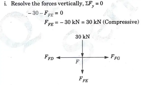
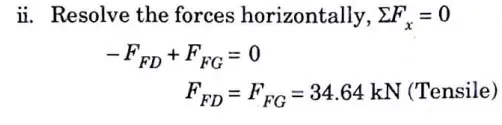
3. Consider the Equilibrium of Joint E:
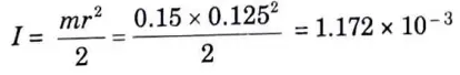
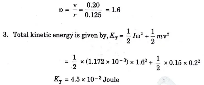
5a. State work energy principle. A uniform cylinder of 125 mm radius has a mass of 0.15 kg. This cylinder rolls without slipping along a horizontal surface with a translation velocity of 20 cm/sec. Determine its total kinetic energy.
Ans. Work Energy Principle: According to the “work-energy principle,” the change in a body’s kinetic energy during any displacement is equal to the work performed by the net force acting on the body, or we can say that the change in a body’s kinetic energy equals the work performed.
Numerical :
Given: Radius of cylinder, r = 125 mm, Mass of cylinder= 0.15 kg, Translation velocity, v = 20 cm/sec
To Find : Total kinetic energy.
1. Moment of inertia,
2. Angular velocity,
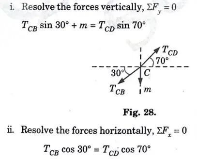
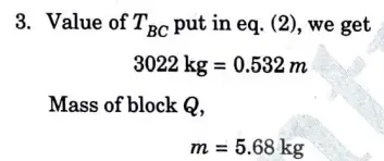
b. Block Pof mass 5 kg and block Q of mass ‘m’ kg are suspended through the chord, which is in the equilibrium position, as shown in given Fig. 25. Determine the mass of block Q.
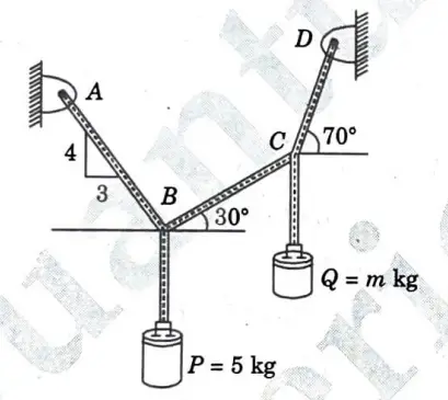
Ans. Given: Mass of block P = 5 kg.
To Find: Mass of block Q
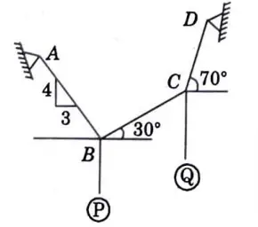
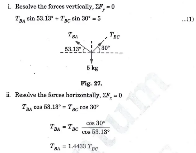
1. Consider the Equilibrium of Joint B :
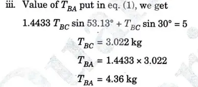
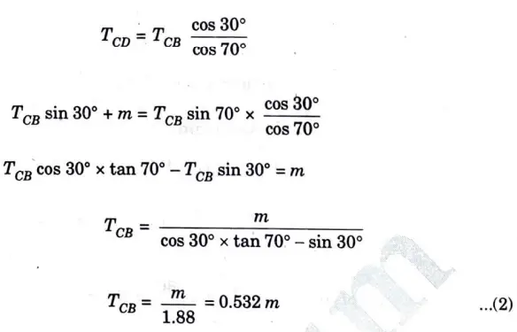
2. Consider the Equilibrium of Joint C:
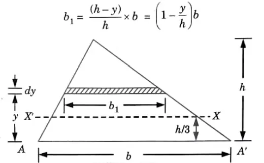
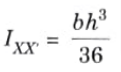
6a. Derive an equation for moment of, inertia of triangle centroidal axis and about its base.
Ans. 1. Consider an elemental strip at a distance y from the base AA’. Let dy be the thickness of the strip and dA its area. Width of this strip is given by,
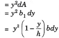
2. Moment of inertia of this strip about AA’,
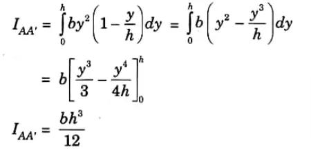
3. Moment of inertia of the triangle about AA’,
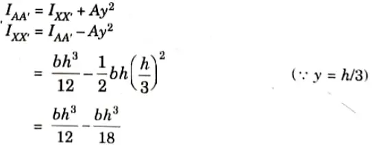
4. By parallel axis theorem,
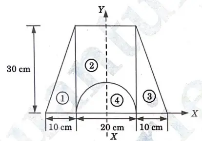
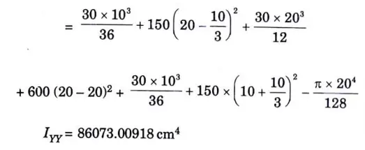
6b. Find the moment of inertia of shaded area shown in given Fig. 29, about x-x axis and Y·Y axis.
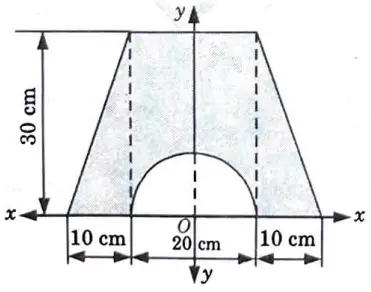
Ans. Given: Fig, 29.
To Find: Moment of inertia.of shaded part.
A. The Position of the Centroid :
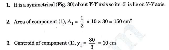
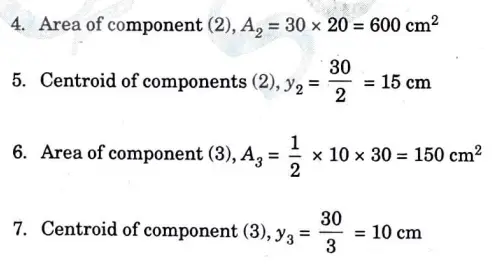
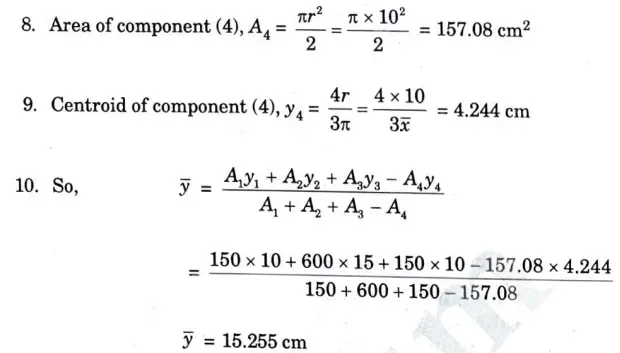
11. Coordinates of centroid of shaded area is (20, 15.255) from left bottom corner.
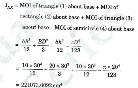
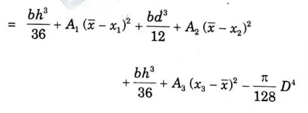
12. Moment of inertia about X-X axis.
13. Moment of inertia about Y-Y axis
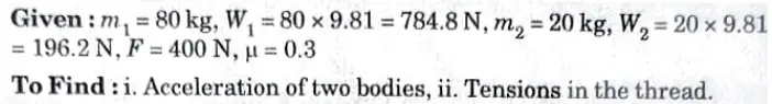
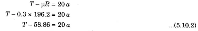
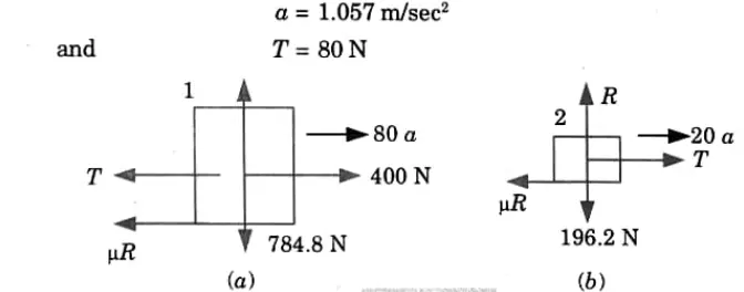
7a. Two bodies A and B of mass 80 kg and 20 kg are connected by a thread and move along a rough horizontal plane under the action of a force 400 N applied to the first body of mass 80 kg as shown in given Fig. 31. The coefficient of friction between the sliding surfaces of the bodies and the plane is 0.3. Determine the acceleration of the two bodies and the tension in the thread, using D’ Alembert’s principle.
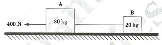
Ans.
1. Let us consider, both the blocks are moving with acceleration and tension developed in thread is T.
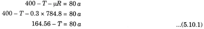
2. Considering FBD of Block 1 (Pig. 5.10.2 (a))
Using D’Alembert’s principle,
3. Considering FBD of Block 2 (Fig. 5.10.2(b))
Using D’Alembert’s principle,
4. On solving the eq. (5.10.1) and eq. (5.10.2), we get
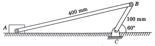
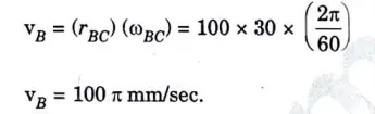
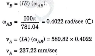
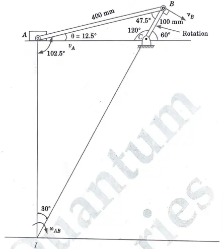
7b. The crank BC of a slider crank mechanism is rotating at constant speed of 30 rpm, as shown in given Fig. 32 clockwise. Determine the velocity of the crosshead A at the given instant.
Ans.
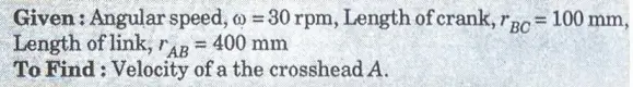
1. Crank BC (Performs rotational motion about point C) :
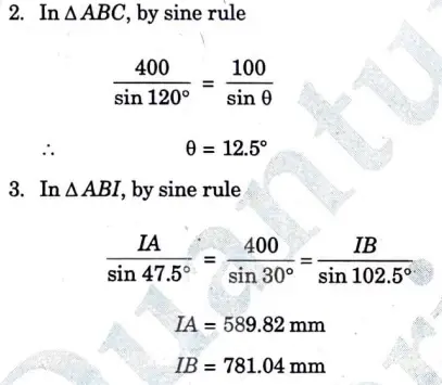
4. Link AB (Performs general plane motion):
At the given instant point I is the instantaneous centre of rotation.

Engineering Mechanics Quantum, Syllabus, Important Questions
| Label | Link |
|---|---|
| Subject Syllabus | Syllabus |
| Short Questions | Short-question |
| Important Unit-1 | Unit-1 |
| Important Unit-2 | Unit-2 |
| Important Unit-3 | Unit-3 |
| Important Unit-4 | Unit-4 |
| Important Unit-5 | Unit-5 |
| Question paper – 2021-22 | 2021-22 |
Engineering Mechanics Quantum PDF: | AKTU Quantum PDF:
| Quantum Series | Links |
| Quantum -2022-23 | 2022-23 |
AKTU Important Links | Btech Syllabus
| Link Name | Links |
|---|---|
| Btech AKTU Circulars | Links |
| Btech AKTU Syllabus | Links |
| Btech AKTU Student Dashboard | Student Dashboard |
| AKTU RESULT (One VIew) | Student Result |