
The first unit of Computer Organization and Architecture introduces the basic ideas of computer organization and architecture. The von Neumann model, instruction set architecture, processor structure, and computer arithmetic are all covered.
Dudes 🤔.. You want more useful details regarding this subject. Please keep in mind this as well.

Important Questions For Computer Organization and Architecture:
*Unit-01     *Unit-02
*Unit-03    *Unit-04
*Unit-05    *Short-Q/Ans
*Question-Paper with solution 21-22
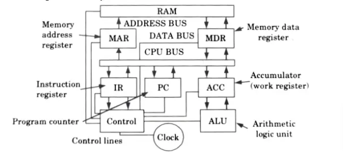
Q1. Draw a block diagram of a computer’s CPU showing all the basic building blocks such as program counter, accumulator, address and data registers, instruction register, control unit etc., and describe how such an arrangement can work as a computer, if connected properly to memory, input/output etc.
Ans. Block diagram of computer’s CPU:
A computer performs five major operations. These are :
- 1. It accepts data or instructions as input.
- 2. It stores data and instruction.
- 3. It processes data as per the instructions.
- 4. It controls all operations inside a computer.
- 5. It gives results in the form of output.
Arrangement of CPU, memory, input/output to work as a computer:
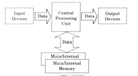
a. Input unit : The user enters data and programmes into the computer system using this device to process them.
b. Storage unit : Before and after processing, data and instructions are kept in the storage device.
c. Output unit : The result that the computer produces as output after processing is stored in the output unit.
d. Processing unit : The task of performing operations like arithmetic and logical operations is called processing.
Based on the instructions given and the kind of data provided, the Central Processing Unit (CPU) uses the data and instructions from the storage unit to perform a variety of calculations. Then it is returned to the storage space.
Q2. Write a short note on bus arbitration.
Ans.
- 1.Bus arbitration is a method that selects the current master who has access to the bus.
- 2. It is possible for more than one master or slave unit to simultaneously seek access to a shared bus that connects several masters and slave units.
- 3. In such situation, bus access is given to the master having highest priority.
- 4. Three different mechanisms are commonly used for this:
i. Daisy chaining:
- a. Daisy chaining method is cheaper and simple method.
- b. All master make use of the same line for bus request.
- c. The bus grant signal passes through each master in a serial fashion until it comes across the first one that is requesting.
ii. Parallel arbitration: Two components make up the parallel arbitration: a priority encoder and a decoder. Each bus arbitrator in this system has an input line and an output line for bus requests.
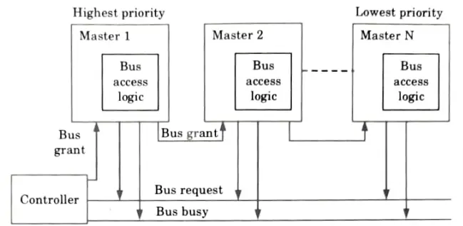
iii. Independent priority: Each master in this system has a unique pair of bus request and bus grant lines, and each pair is given a priority.
Q3. Discuss the advantages and disadvantages of polling and daisy chaining bus arbitration schemes.
Ans. Daisy chaining:
1. In this, all masters make use of the same line for bus request.
2. Up until it comes across the first master who is making a request for access to the bus, the bus grant signal travels serially through each master.
3.This master initiates the busy line, disables the bus grant signal from spreading, and takes over the bus.
4. Therefore, any additional asking module won’t receive the grant signal and won’t be able to use the bus.
Advantages of daisy chaining :
1. It is a simple and cheaper method.
2. It requires the fewest lines, and this quantity is unaffected by the system’s master count.
Disadvantages of daisy chaining:
1. The number of masters in the system directly affects how long it takes for the bus grant signal to propagate. As a result, there are fewer masters in the system and arbitration takes longer.
2. The physical location of the master determines the master’s priority.
3. Failure of any one master causes the whole system to fail.
Advantages of polling bus arbitration:
1.The system does not fail if one module fails.
2. By changing the polling sequence that is stored in the controller, the priority can be modified.
Disadvantages of polling bus arbitration:
1. More bus request and grant signals are necessary (2 x n signals for n modules).
2. The overhead of polling might take up a lot of CPU time.
Q4. Explain the operation of three state bus buffers and show its use in design of common bus.
Ans.
- 1. A three state gate is a digital circuit that exhibits three states.
- 2. Two of the states are signals equivalent to logic 1 and 0.
- 3. The third state is a high-impedance state.
- 4. The output is unconnected and has no logic relevance in the high-impedance condition since it functions like an open circuit.
- 5. Any traditional logic operation, such as AND or NAND, can be carried out using three state gates.
- 6. The buffer gate, however, is the one that is most frequently incorporated into bus system designs.
- 7. The graphic symbol of a three state buffer gate is shown in Fig.
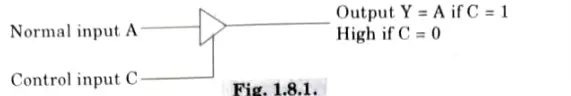
- 8. The output state is determined by the control input. The output is enabled and the gate opens when the control input is equal to 1.
- 9. behaves like any conventional buffer, with the output equal to the normal input.
- 10. Regardless of the value in the normal input, the output is disabled and the gate enters a high state when the control input is set to 0.
- 11. Without risking loading effects, many three state gate outputs can be wired together to form a single bus line.
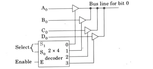
- 12. The outputs of four buffers are connected together to form a single bus line.
- 13. Which of the four regular inputs will communicate with the bus line is determined by the control inputs to the buffers.
- 14. Not more than one buffer may be in the active state at any given time.
- 15. We require n circuits with four buffers each in order to build a common bus for four registers with n bits each utilizing three state buffers.
- 16. The four registers send one significant bit to each group of four buffers.
- 17. Only one decoder is necessary to select between the four registers.
Q5. What is a memory stack ? Explain its role in managing subroutines with the help of neat diagrams.
Ans. Memory stack: Memory stack is a collection of memory locations accessed by the CPU during processing operations and temporarily saved in registers.
Role in managing subroutines :
- 1. The stack facilitates programme execution by automatically updating process-state information.
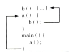
- 2. If the main routine of a program, for example, invokes function a( ), which in turn invokes function b ( ), function b ( ) will eventually return control to function a ( ), which in turn will return control to the main ( ) function as shown in Fig.
- 3. The sequence of return addresses must be stored in order for control to be transferred to the correct destination.
- 4.Because it is a dynamic data structure and can accommodate any amount of nesting within memory limits, a stack is an excellent choice for keeping track of this information.
- 5. The location of the subsequent instruction to be executed in the calling routine is pushed onto the stack when a subroutine is called.
- 6. When the subroutine returns, this return address is popped from the stack, and program execution jumps to the specified location as shown in Fig.
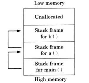
- 7. the process at any given instant.
- 8. The stack is used to store the return address, local (or automated) variables, and the inputs to the procedure.
- 9. A frame is the name given to the data that a function call pushes into the stack. The frame or base pointer register contains the address of the current frame.
- 10. The frame pointer for the calling function is also pushed onto the stack when a subroutine is called so that it can be restored once the subroutine leaves.
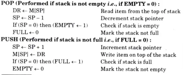
Q6. What is stack ? Give the organization of register stack with all necessary elements and explain the working of push and pop operations.
Ans.
- 1. An ordered group of components known as a stack allows for one element to be accessed at a time.
- 2. The point of access is called the top of the stack.
- 3. The number of elements in the stack or length of the stack is variable.
- 4. Items may only be added or deleted from the top of the stack.
- 5. A stack is also known as a pushdown list or a Last-In-First-Out (LIFO) list.
Organization of register stack:
Consider the organization of a 64-word register stack as illustrated in Fig.
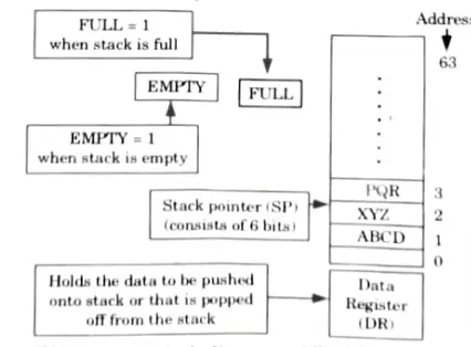
The four separate registers used in the organization are:
1. Stack Pointer register (SP): It has a value of 6 bits in binary, which corresponds to the stack’s top address. In this case, the stack pointer SP has six bits and is limited to a value of 111111, or the value 63.
2. FULL register: It can store 1 bit information. It is set to 1 when the stack is full.
3. EMPTY register: It can store 1 bit information. It is set to 1 when stack is empty.
4. Data Register (DR): It holds the data to be written into or to be read from the stack.
Working of POP and PUSH:

Computer Organization and Architecture Quantum PDF, Syllabus, Important Questions
| Label | Link |
|---|---|
| Subject Syllabus | Syllabus |
| Short Questions | Short-question |
| Important Unit-1 | Unit-1 |
| Important Unit-2 | Unit-2 |
| Important Unit-3 | Unit-3 |
| Important Unit-4 | Unit-4 |
| Important Unit-5 | Unit-5 |
| Question paper – 2021-22 | 2021-22 |
Computer Organization and Architecture Quantum PDF | AKTU Quantum PDF:
| Quantum Series | Links |
| Quantum -2022-23 | 2022-23 |
AKTU Important Links | Btech Syllabus
| Link Name | Links |
|---|---|
| Btech AKTU Circulars | Links |
| Btech AKTU Syllabus | Links |
| Btech AKTU Student Dashboard | Student Dashboard |
| AKTU RESULT (One VIew) | Student Result |
2 thoughts on “Unit 01 Introduction in Computer Organization and Architecture”