
With our AKTU question paper and solution on Computer Graphics, set off on a vibrant trip. The thrill of producing and exploring digital photographs is introduced to young learners through Student-friendly notes.
Dudes 🤔.. You want more useful details regarding this subject. Please keep in mind this as well.

Important Questions For Computer Graphics:
*Quantum          *B.tech-Syllabus
*Circulars           *B.tech AKTU RESULT
* Btech 3rd Year
Section A: Computer Graphics Short Answers
a. What is the difference between raster and random scan ?
Ans.
| S. No. | Raster scan display | Random scan display |
| 1. | It is highly suited for the realistic presentation of scenes with fine colour and shading patterns. | It is not capable of displaying realistic shaded scenes because it is meant for line drawing applications. |
| 2. | Raster scan have low resolution than random system. | Random scan have higher resolution than raster system |
| 3. | Picture definition is stored in form of pixel intensity value. | Picture definition is stored in form of line drawing algorithm. |
b. What is the role of frame buffer is raster method ?
Ans. Role of pixel: The smallest object or colour spot that may be displayed or addressed on a monitor is called a “pixel.” They stand in for the tiniest manipulable component of a picture displayed on the screen.
Role of frame buffer: The refresh buffer, also known as the frame buffer, is where images’ definitions are kept in memory. For each screen point, it stores the collection of intensity values.
c. What is the difference between computer graphics and image processing?
Ans. An image processing is a process where 2-dimensional plane of pixels are processed where every pixel have a domain of colors whereas computer graphics is a graphical object-oriented framework, which can be 1-dimensional (vector), 2-dimensional plane), 3-dimensional (object), 4-dimensional (animation).
d. Distinguish between pixel ratio and aspect ratio.
Ans.
| S. No. | Pixel ratio | Aspect ratio |
| 1. | The width to height ratio of a single pixel is known as a pixel ratio. | The aspect ratio is the proportion of an image’s width to height. |
e. What is the difference between generation of character by stroke and bitmap method?
Ans.
| S. No. | Stroke method | Bitmap method |
| 1. | The stroke approach is based on how text is naturally written by humans. This approach involves drawing the graph line by line. | The dot-matrix approach, often known as the bitmap method, uses an array of bits to create characters. |
| 2. | This method uses small line segments to generate a character. | This method uses dots to generate a character. |
f. What do you mean by 3-D geometry ?
Ans. 3-D geometry is a branch of geometry that deals with the mathematical representation of 3-D shapes using the x, y, and z-coordinates.
g. What do you mean by composite transformation ?
Ans.
- 1. A composite transformation is two or more transformations performed one after the other.
- 2. Ifa transformation of the plane T1 is followed by a second plane transformation T2, then the result itself may be represented by a single transformation T which is the composition of T1 and T2 taken in that order.
- 3. This is written as T = T1.T2
- 4. Composite transformation can be achieved by concatenation of transformation matrices to obtain a combined transformation matrix.
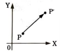
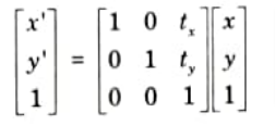
h. Explain 2 D translation with diagrams.
Ans. Translation:
a. Translation is a process of changing the position of an object in a straight line path from one coordinate location to another.
b. We can translate a two dimensional point by adding translation distances, tx and ty to the original coordinate position (x, y) to move the point to a new position (x’, y’), as shown in the Fig
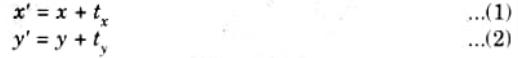
c. The translation distance pair (tx, ty)is called translation vector.
d. Translation equation (1) and (2) can be represented in the form of matrix as:
i. List the properties of Bezier Curves.
Ans. Properties of Bezier curves are:
- 1. It always passes through the first and last point.
- 2. It lies within the convex hull of the control points.
- 3. The sum of all Bezier blending function is equal to one.
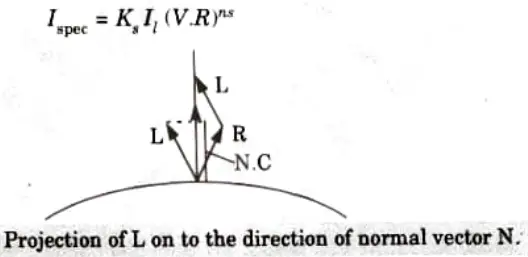
j. What is specular reflection ?
Ans.
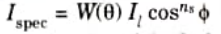
where Il is the intensity of the light source, ns is specular reflection parameter and 𝝓 is the viewing angle relative to specular reflection direction R.
Section B: Computer Graphics Long Questions
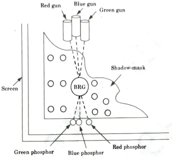
a. What do you understand by shadow mask CRT? Give its advantages and disadvantages.
Ans.
- 1. Three electron beams typically sweep back and forth across a metal screen known as a shadow mask in colour tubes.
- 2. Thousands of small holes are dotted across this mask.
- 3. A group of red, green, and blue phosphor dots are located in front of each hole on the faceplate.
- 4. One point of light is produced by each cluster, and the three beams that travel through each hole regulate its colour and intensity.
- 5. The shadow mask ensures that the blue beam, for example, strikes only blue phosphors, because the two other phosphor colors lie in the mask’s “shadow”.
Advantages of shadow-mask method (of CRT):
- 1. The whole of the screen is constantly updated.
- 2. It allows even the solids to be displayed.
- 3. It leverages low-cost CRT hardware.
- 4. It is a bright light-emitting display technology.
Disadvantages of shadow-mask method:
- 1. It requires a very large memory array equal to that of our screen size.
- 2. It performs discrete spatial sampling of pixels.
- 3. Varying angles of e– beam, approach the CRT face. Hence, convergence is difficult.
- 4 It results in spurious X-ray radiations also.
- 5. It requires proper matching of shadow-mask and dot-pitch frequencies.
b. Explain 3-dimensional clipping ? What are the problems that are encountered in perspective projections ?
Ans. 3D clipping:
- 1. Extending techniques for two-dimensional clipping can be used to create three-dimensional clipping.
- 2. With 3D clipping, the objects are clipped against the view volume’s boundary planes.
- 3. We would need to test the relative location of the line using the boundary plane equations for the view volume in order to clip a line segment against it.
- 4. By modifying the plane equation of each boundary to include the line endpoint coordinates, which establishes whether the endpoint is inside or outside that boundary.
- a. An endpoint (x, y, z) of a line segment is outside a boundary plane if Ax + By + Cz + D > 0.
- b. Similarly, the point is inside the boundary if Ax + By + Cz +D < 0.
- c. Lines with both endpoints outside a boundary plane are discarded, and those with both endpoints inside all boundary planes are saved.
- 5. The intersection of a line with a boundary is found using the line equations along with the plane equation.
- 6. Intersection coordinates (x1, y1, z1) are values that are on the line and that satisfy the plane equation Ax1 + By1 + Cz1 + D = 0, where A, B, C, and D are the plane parameters for that boundary.
Problem encountered with perspective projection:
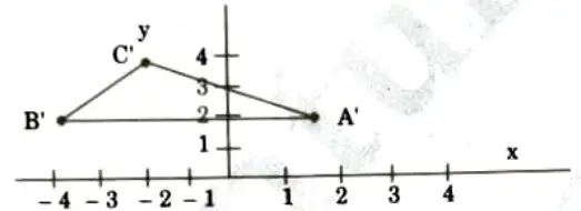
- 1. The foreshortening of distant lines due to perspective. For instance, both item A and B’s projections in the illustration are of the same size. Apart from the projection’s centre, objects appear smaller.
- 2. On the view plane, perspective projections of objects beyond the projection’s centre seem reversed and upside down.
- 3. The information is lost since the relative proportions of the items are not kept.
c. What do you understand by clipping? Give Liang-Barsky’s line clipping algorithm.
Ans. Clipping:
- 1. Clipping is the procedure that identifies those portions of a picture that are either inside or outside of a specific region of space.
- 2. Point, line, area or text can be clipped.
- 3. The region against which an object is to be clipped is called clipping window.
The Liang-Barsky algorithm:
1. Read two endpoint of the line say P1 (x1, y1) and P2 (x2, y2).
2. Read two corners (left-top and right-bottom) of the window, say
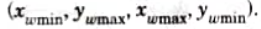
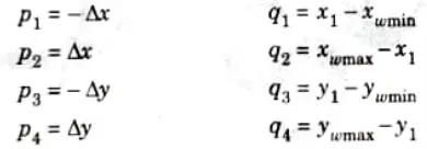
3. Calculate the values of parameters pi and qi for i = 1, 2, 3, 4 such that
4. If pi = 0, then
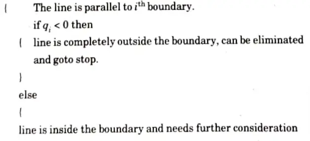
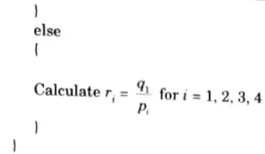
5. For all k such that pk < 0 calculate rk = qk/pk. Let u1 be the maximum of the set containing 0 and the various values of r.
6. For all k such that pk > 0 calculate rk = qk/pk. Let u2 be the maximum of the set containing 1 and the calculated r values.
7. If u1 > u2, eliminate the line since it is completely outside the clipping window, otherwise use u1 and u2 to calculate the endpoint of the clipped line.
B. Stop.
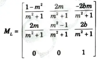
d. Explain reflection in detail. What is reflection about an arbitrary line ?
Ans. Homogenous transformation:
- 1. The definition of homogeneous coordinates states that they are the coordinates that multiply all of the geometric transformation equations.
- 2. Coordinates are represented with three element column vectors, and transformation operations are written as 3 x 3 matrices. For translation we have:
Which we can write in the abbreviated form as
- 3. The inverse of translation matrix is obtained by replacing the translation parameters tx and ty with their negatives i.e., -tx and -ty.
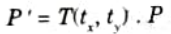
- 4. Rotation transformation equations about the coordinate origin are now written as:
We get the inverse of rotation matrix when 𝜽 is replaced with – 𝜽.
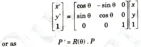
- 5. Finally a scaling transformation relative to the coordinate origin is now expressed as matrix multiplication.
Replacing these parameters with their multiplicative inverse (1/sx and 1/sy) yields the inverse scaling matrix.
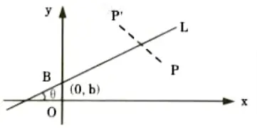
1. Let line L(y = mx + b) have a y-intercept (0, b) and an angle 𝜽 with respect tox-axis.
2. The steps involved in reflection transformation are as follows:
- a Translate the intersection point B to the origin.
- b. Rotate by 𝜽° so that the line L aligns with the x-axis.
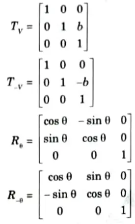
- c. Mirror reflects about the r-axis.
- d. Rotate back by 𝜽°.
- e. Translate B back to (0,b).
Therefore, we have
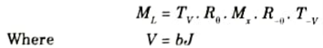
After multiplication of all basic matrix, we get
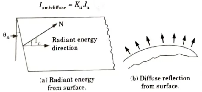
e. Draw a simple Illumination model. Include the contribution of Diffuse, Ambient and Specular Reflection.
Ans. Illumination model:
1. Ambient light:
- i. According to this model, the optical characteristics of each surface affect how much light is reflected from it.
- ii. Ambient light lacks any directional or spatial properties.
- iii. The amount of ambient light that strikes every surface of an object is constant across all surfaces and directions.
- iv. The optical characteristics affect how much of the incident energy will be absorbed vs reflected.
2. Diffuse reflection:
- i. In this model, the walls, floor, ceiling, etc. reflect light coming from all sides.
- ii. No matter which direction the viewer is looking from, diffuse reflections are constant across all surfaces in a scene.
- iii. The amount of diffused reflected light for each surface in a scene can be set with parameter Kd.
- iv. For the surfaces which absorbs most of the incident light (black surfaces), the value of the diffuse reflection coefficient (Kd) is close to 0.
- v. If a surface is exposed to only ambient light, then the intensity of the diffuse reflection at any point on the surface is given by
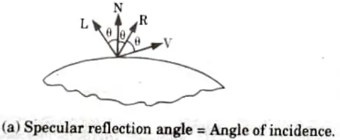
Specular reflection:
- 1. The whole or almost total reflection of the light in a focused area around the specular reflection angle produces specular reflection.
- 2. When we look in a particular direction at a lit shining surface, such as polished metal, a shiny apple, or a pearl, we see a bright spot or a highlighted spot.
- 3. In the Fig.(a) the specular reflection angle, denoted by 𝜽 is the same as the angle of incident light and N is the unit normal surface vector, R is the unit vector in the direction of ideal specular reflection, L is the unit vector directed towards the point light source, and V is the unit vector pointing towards the viewer from the surface position.
- 4. Angle 𝜽 is the viewing angle relative to the specular reflection direction R.
- 5. In the case of an ideal reflector or perfect mirror, the incident light is reflected only in the specular reflection direction.
- 6. In this case, we would only see reflected light when vectors V and R coincide, i.e., 𝜽 = 0. The objects other than ideal reflectors have specular reflection around vector R.
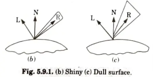
Phong model:
- i. According to the Phong model, the intensity of specular reflection is proportional to cosns 𝜽. The value of n, specular reflection parameter is determined by the type of surface.
- ii. For very shiny surfaces, the value of ns is large (more than 100) and for dull surfaces the value of ns is close to 1. For a perfect reflector, the value of ns is infinite.
- iii. The intensity of specular reflection depends on the angle of incidence, on the properties of the surface, colour of incident light and polarization.
- iv. The specular reflection coefficient W(𝜽), for each surface may be used to model the monochromatic specular intensity variation.
- v. We can write the Phong specular reflection model as

where Il is intensity of light source, and 𝜽 is the viewing angle relative to specular reflection direction R.
- vi. In the case of opaque materials, the specular reflection rejection is almost constant for all incidence angles. Therefore, replacing W(𝜽) with a constant specular reflection coefficient Ks. Since V and R are unit vectors in the viewing and specular reflection directions, cos 𝜽 = VR. We can rewrite the equation (5.8.1) as
Section 3: Bresenham Algorithm
a. Consider two raster systems with resolutions of 640* 480 and 1280* 1024. How many pixels could be accessed per second in each of these systems by a display controller that refreshes the screen at a rate of 60 frames per second ?
Ans. Number of pixel in one frame (resolution) = Number of column (width) x Number of row (height)
Number of frame in one second = 60 frames
So, number of pixel in 60 frames = resolution x 60
Hence,
a. For resolution 640 x 480
Number of pixels per second = 640 x 480 x 60 = 1843200 pixel
b. For resolution 1024 x 1280
Number of pixels per second 1024 x 1280 x 60 = 78643200 pixel
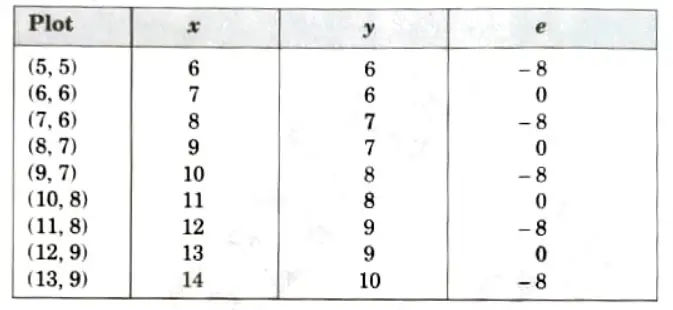
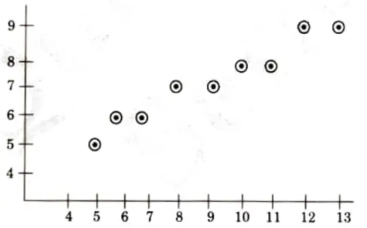
b. Consider the line from (5, 5) to (13, 9). Use the Bresenham algorithm to rasterize the line.
Ans. Given:
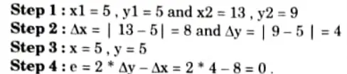
Tabulating the result of each iteration:
Section 4: Cohen-Sutherland Algorithm
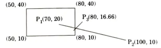
a. Use the Cohen-Sutherland algorithm to clip line P1 (70, 20) and P2(100, 10) against a window lower left hand corner (50, 10) and upper right hand corner (80, 40).
Ans. Given: P1(70, 20) and P2(100, 10)
Window lower left corner = (50, 10)
Window upper right corner = (80, 40)
Now, we assign 4 bits binary out code.
Point P1 is inside the window so the out code of P1 = 0000 and the out code for P2 = 0010.
Logical AND operation will give, 0000
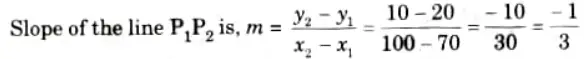
We, have to find intersection of line P1P2 with right edge of window i.e.. P2(x, y).Here x = 80 we have find the value of y.
We use the point P2(x2, y2) = P2(100, 10)
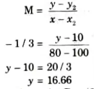
thus, the intersection point P3 = (80, 16.66)
So, after clipping line P1,P2 against the window, new line is P1,P3 with co-ordinates P1(70,20) and P3(80, 16.66)
b. Obtain the mirror reflection of the triangle formed by the vertices A(0, 3), B(2, 0) and C(3, 2) about the line passing through the points (1, 3) and (-1,-1).
Ans. The equation of the line passing through the points (1, 3) and (-1, – 1) is obtained as:

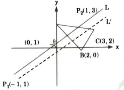
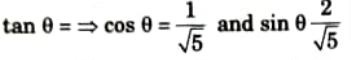
If 𝜽 is the angle made by the line (1) with the positive z-axis, then
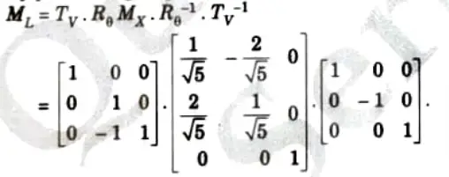
To obtain the reflection about the line (1), the following sequence of transformations can be performed:
- 1. Translate the intersection point (0, 1) to the origin, this shift the line L to L’
- 2. Rotate the shifted line L’ by – 𝜽° (ie. clockwise), so that the L’ aligns with the x-axis.
- 3. Perform the reflection about r-axis.
- 4. Apply the inverse of the transformation of step (2).
- 5. Apply the inverse of the transformation of step (1).
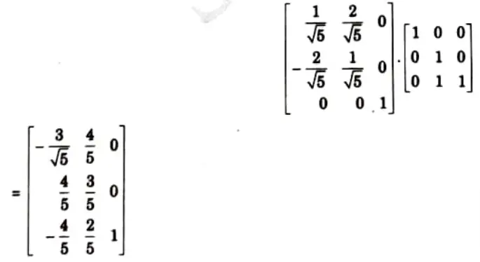
By performing step 1 to step 5, we get
So the new coordinates A’B’C’ of the reflected triangle ABC can be found as
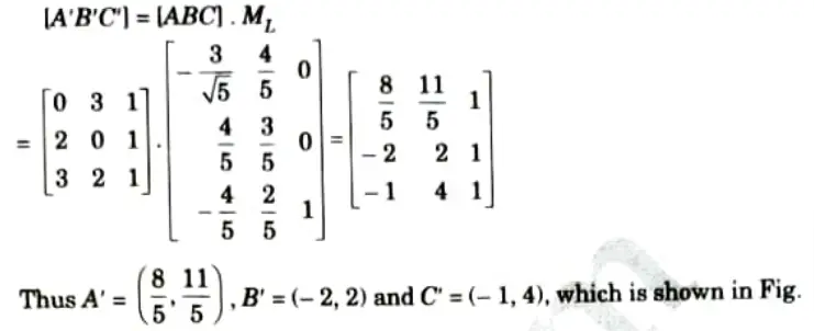
4.
Section 5: Parallel Projection and Perspective Projection
a. What is window-to-view point coordinate transformation ? What are issues related to multiple windowing ?
Ans. Window to view point coordinate transformation: Window to viewport mapping or transformation is done in following three steps:
Step 1: The object together with its window is translated until the lower left corner of the window is at the origin.
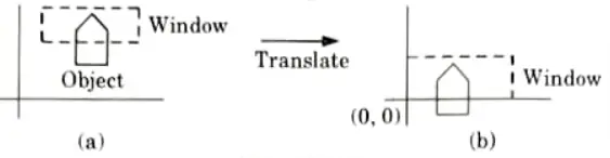
Step 2: The object and the window are then scaled until the window has the dimension same as viewport. In other words, we are converting the object into image and window in viewport.
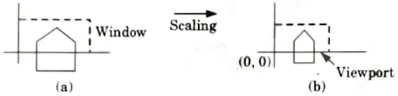
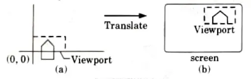
Step 3: The final transformation step is another translation to move the viewport to its correct position on the screen.
Issues related to multiple windowing:
- 1. A key problem in multi-windowing is how to automatically assign windows to the relevant areas within an image.
- 2. More difficult to work with several applications at once.
b. What do you mean by projection ? Differentiate between parallel projection and perspective projection.
Ans. Projection:
- 1. A projection is a two-dimensional representation of a three-dimensional item or scene; it is the shadow of the object.
- 2. Projections convert coordinate system points of dimension ‘n’ into coordinate system points of dimension ‘n’ less.
Types of projections :
- 1. Parallel projection:
- a. Parallel lines are used to translate coordinate points to the view plane in a parallel projection.
- b. These are linear transforms that can be used to create scale drawings of three-dimensional objects for use in blueprints.
- 2. Perspective projection:
- a. A perspective projection transforms the locations of objects to the view plane via lines that converge at the centre of the projection.
- b. Calculating the point at which the projection lines and the view plane intersect provide the projected view of an object.
Difference:
| S. No. | Parallel projection | Perspective projection |
| 1. | When an object is projected in parallel, parallel lines are drawn from each of its vertices all the way to the view plane. | Perspective projection produces realistic view. |
| 2. | Lanes of projection are parallel. | Lines of projection are not parallel. |
| 3. | These are linear transform. | These are non-linear transform. |
| 4. | In parallel projection, the center of projection is at infinity. | In perspective projections, the center of projection is at a point. |
Section 6: Z-Buffer Algorithm
a. What do you understand by the term “Back-Face Removal” ? Explain a Back-Face Removal algorithm, you find convenient to implement. Justify your answer.
Ans. Back-face detection method:
1. Object surfaces that are orientated away from the viewer are called back-faces.
2. Algorithm used to detect the back-faces is known as back-face detection algorithm.
3. If any three points (x1, y1, z1), (x2, y2, z2) and (x3, y3, z3) on any plane surface are known, the unknown parameters A, B, C and D of the plane Surface equation Ax + By + Cz + D = 0 can be found as follows:
i. All the three points (x1, y1, z1), (x2, y2, z2) and (x3, y3, z3) should satisfy the equation Ax + By + Cz + D = 0 as it lies on the surface.
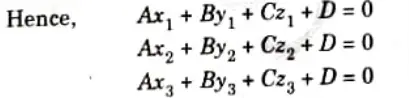
ii. Also, any arbitrary point (x, y, z) lying on the surface should satisfy the equation of the desired surface
Ax + By +Cz +D = 0
iii. A unique solution of equations for A, B, C and D can only be obtained if
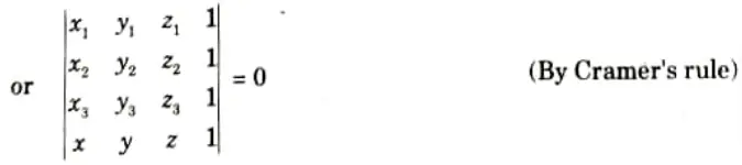
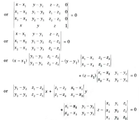
which is in the form of Ax + By + Cz + D =0, giving the equation of the plane passing through the three points
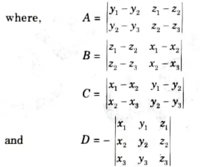
iv. Any plane with its inside and outside surfaces can be defined by three points and its normal vector.
v. This normal vector can be calculated with three position vectors of three points (x1, y1, z1), (x2, y2, z2) and (x3, y3, z3).
vi. Using right hand thumb rule, the three points are considered in counter clockwise manner for calculating the unit normal directing outside the surface. Thus, the surface normal and equation of the plane are calculated.
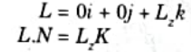
vii. Now, if any point (x, y, or z) lies inside the polygon surface, Ax + By + Cz + D < 0, and if it is along the line of sight to the surface, the polygon must be back-face.
viii. If L is the line of sight or viewing vector (light vector in case of shadowing), perpendicular to the viewing plane originating from the eye or camera. Nis the unit surface normal vector as shown in Fig.(a) and (b) the polygon is the back-face if L.N > 0.
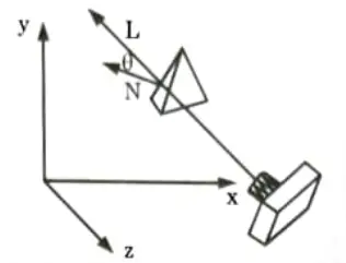
ix. On aligning the light vector to that of the view vector which is normally along negative z-axis for right-handed viewing system, that is
x. Hence, only z-component of normal vector N is required to be considered, and the sign of K is checked for negative value.
xi. Thus, any polygon is a back-face if it has a surface normal with negative z-component value.
b. Explain Z-Buffer algorithm.
Ans.
- 1. The rendering system’s visibility detection approach is the A-buffer method.
- 2. To enable transparency, the A-bufter builds on the depth buffer technique. The accumulation buffer is the main data structure of the A-buffer.
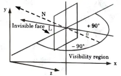
- 3. Each position in the A-buffer has two fields:
- a. Depth field: It stores a positive or negative real number.
- b. Intensity field: It stores surface intensity information or a pointer value.
- 4. If depth >=0, the number stored at that position is the depth of a single Surface overlapping the corresponding pixel area.
- 5. The intensity field then stores the RGB components of the surface colour at that point and the percent of pixel coverage.
- 6. If depth < 0, it indicates multiple surface contributions to the pixel intensity.
- 7. The intensity field then stores a pointer to a linked list of surface data.
- 8. The surface buffer in the A-buffer includes:
- a. RGB intensity components
- b. Opacity parameter
- c. Depth
- d. Percent of area coverage
- e. Surface identifier
- 9. The depth and opacity values are used to determine the final colour of a pixel.
Section 7: Quadric Surfaces
a. What do you understand by quadric surfaces ?
Ans. Quadric surfaces: Quadric surfaces are defined by quadrate equations in two dimensional space.
Various types of quadratic surfaces:
1. Sphere:
a. A sphere with a radius r is defined as the set of points (x, y, z) that satisfies the following equations
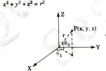
b. The parametric equations for spherical surfaces are:
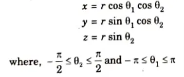
2. Ellipsoid:
a. An ellipsoid surface is the extension of a spherical surface. There are three mutually perpendicular radii that have different values as shown in Fig.
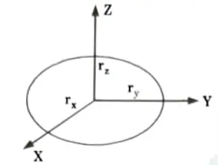
b. In the cartesian coordinate system, the ellipsoid centered at the origin can be defined as:
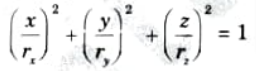
c. The parametric equations are:
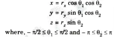
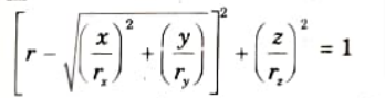
3. Torus:
a. A doughnut-shaped object as shown in Fig. is called a torus.
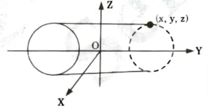
This can be generated by rotating a conic object like a circle about a specified axis.
b. In cartesian coordinates, equations for points over the surface of a torus is given as
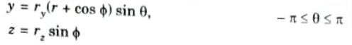
c. The parametric representations for a torus can be given as

b. Explain the difference between:
i. Bezier and B-Spline curves
ii. Bezier and Hermite curves
Ans. i. Bezier and B-Spline curves
| S. No. | B-spline | Bezier |
| 1. | An inflexible Bernstein basis function is used to specify the B-spline curves. | A characterizing matrix, blending functions, or boundary constraints can all be used to specify Bezier curves. |
| 2. | The curves produced when an open uniform basis function is used are quite similar to Bezier curves. | The curve generally follows the shape of defining polygon. |
| 3. | These curves can used to construct blending curves. | Bezier curves are found in painting & drawing packages as well as CAD system. |
| 4. | The degree of the generated curve is independent of the number of vertices because the B-spline permits the order of the basis function. | One fewer degree exists in the polynomial describing the curve segment than there are defining polygon points. |
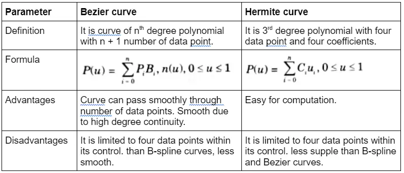
ii. Bezier and Hermite curves
6 thoughts on “Computer Graphics: Previous Question Paper with Answer,Aktu Notes”