
Table Of Contents
With Aktu’s Quantum Notes, unlock your B.Tech success. Discover the world of computer graphics by reading these important notes that include vital and recurrent questions. It’s simple to do well on tests! Unit-5 Hidden Lines and Surfaces
Dudes 🤔.. You want more useful details regarding this subject. Please keep in mind this as well.

Important Questions For Computer Graphics:
*Quantum               *B.tech-Syllabus
*Circulars                *B.tech AKTU RESULT
* Btech 3rd Year    * Aktu Solved Question Paper
Q1. Explain z-buffer algorithm.
Ans. z-buffer/Depth-buffer algorithm:
- 1. The frame buffer concept is simply extended with the z-buffer concept. The intensity of each pixel in image space is kept in a frame.
- 2. The depth buffer used to hold the z-coordinates, or depth, of each visible pixel in image space is called the “z-buffer.”
- 3. This approach sets up a buffer that holds depth information and is the same size as the frame buffer.
- 4. The depth buffer’s components each correspond to a pixel in the frame buffer and initially store the scene’s maximum depth.
- 5. The depth at each pixel is calculated and compared with the matching depth in the depth buffer as each polygon is scan-converted.
- 6. The pixel is placed in the frame buffer with the polygon colour at that position and the depth buffer is set to the polygon depth if the depth is less than that recorded in the depth buffer (i.e., closer to the viewer).
- 7. The depth buffer at that location is not kept in the frame buffer if the polygon depth is greater (i.e., farther from the viewer).
- 8. The z- buffer algorithm can be stated as:
- Step 1: Initialize frame buffer to background colour.
- Step 2: Initialize z-buffer to minimum z value.
- Step 3: Scan-convert each polygon in arbitrary order.
- Step 4: For each (x, y) pixel, calculated depth ‘z’ at that pixel (z(x,y)).
- Step 5: Compare calculated new depth z(x, y) with value previously stored in z-buffer at the location z(x, y).
- Step 6: If z(x, y) > z(x, y), then write the new depth value to z-buffer and updated frame buffer.
- Step 7: Otherwise, no action is taken.
Q2. Discuss A-buffer method.
Ans.
- 1. The rendering system’s visibility detection approach is the A-buffer method.
- 2. To enable transparency, the A-bufter builds on the depth buffer technique. The accumulation buffer is the main data structure of the A-buffer.
- 3. Each position in the A-buffer has two fields:
- a. Depth field: It stores a positive or negative real number.
- b. Intensity field: It stores surface intensity information or a pointer value.
- 4. If depth >= 0, the number stored at that position is the depth of a single surface overlapping the corresponding pixel area.
- 5. The intensity field then stores the RGB components of the surface colour at that point and the percent of pixel coverage.

- 6. If depth < 0, it indicates multiple surface contributions to the pixel intensity.
- 7. The intensity field then stores a pointer to a linked list of surface data.
- 8. The surface buffer in the A-buffer includes:
- a. RGB intensity components
- b. Opacity parameter
- c. Depth
- d. Percent of area coverage
- e. Surface identifier
- 9. The depth and opacity values are used to determine the final colour of a pixel.
Ans.
- 1. The process that eliminates any surfaces or lines that are not intended to be exhibited in a 3D Scene is known as visible surface detection or hidden surface elimination.
- 2. It is possible to create a method that draws every component of every object in the picture, starting with the one that is located the furthest away from the viewing plane and working its way closer.
- 3. While viewing an image that contains non-transparent surfaces and objects, we are unable to see any items that are visible from behind the non-transparent object. To provide a realistic screen appearance, these hidden surfaces must be removed.
- 4. The hidden surface challenge is the detection and elimination of these surfaces.
- 5. Two approaches for visible surface detection are:
- a. Object space method: In order to decide which surfaces should be classified as visible as a whole, it compares objects and object components to one another inside the scene specification.
- b. Image space method: Visibility of objects is decided point by point at each pixel position on the projection plane.
- 6. The concealed surface problem is solved using the scanline coherence approach, one scanline at a time, from top to bottom.
- 7. The depth buffer is a one-dimensional variant of the simplest scanline method.
- 8. For each overlapping surface in a scanline, depth calculations are performed to identify which is closest to the view plane.
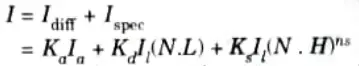
Q4. Discuss combined diffuse and specular reflections with multiple light sources.
Ans. 1. For a single point light source, we can model the combined diffuse and specular reflections from a point on an illuminated surface as
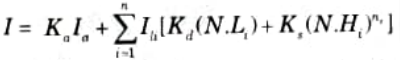
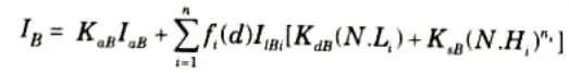
- 2. If we place more than one point source in a scene, we obtain the height reflection at any surface point by summing the contributions from the individual sources:
- 3. We can use a normalization technique to make sure that no pixel intensity exceeds the maximum permitted value.
- 4. A straightforward strategy is to give each element in the intensity equation a maximum magnitude.
- 5. We just set any calculated term to the maximum value if it exceeds the maximum.
- 6. Normalizing the individual components by dividing each by the magnitude of the greatest phrase is another technique to account for intensity overload.
- 7. A more involved process involves first calculating all of the scene’s pixel intensities, then scaling those intensities to the permitted intensity range.
Q5. What do you mean by intensity attenuation?
Ans.
- 1. Any decrease in a signal’s strength is referred to as intensity attenuation.
- 2. It can be relativistically compared to the peak ground acceleration attenuation that is employed in engineering design.
- 3. Understanding intensity attenuation is helpful when calibrating hazard models using prior data.
- 4. Intensity attenuation equation is given by:
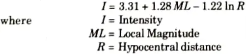
- 5. As radiant energy from a point light source travels through space, its amplitude the is attenuated by the factor I/d2, where d is the distance that light has travelled.
- 6. This means that a surface close to the light source incident receives higher intensity from the source than a distant surface.
Q6. Write a short note on colour considerations.
Ans.
- 1. The majority of realistic-looking graphical displays are in colour. Writing the intensity equation as a function of the colour characteristics of the light sources and object surfaces is necessary to include colour.
- 2. Red, green, and blue components are used to express each colour in an RGB description of a scene.
- 3. The illumination model then calculates the RGB components of the reflected light when we supply the RGB components of light source intensities and surface colours.
- 4. Specifying the reflectivity coefficients as three element vectors is one method of setting surface colours.
- 5. The diffuse reflection coefficient vector would then have RGB components (KdR, KdG, KdB).
- 6. If we want an object to have a blue surface, we select a non-zero value in the range from 0 to 1 for the blue reflectivity component, KdB, while the red and green reflectivity components are set to zero (KdR = KdG = 0).
- 7. Any non-zero red or green components in the incident light are absorbed, and only the blue component is reflected. The intensity calculation for this example reduces to the single expression
- 8. In general, we can select surface colour so that the reflected light has non-zero values for all three RGB components because surfaces are commonly lighted with white light sources.

Computer Graphics Btech Quantum PDF, Syllabus, Important Questions
| Label | Link |
|---|---|
| Subject Syllabus | Syllabus |
| Short Questions | Short-question |
| Question paper – 2021-22 | 2021-22 |
Computer Graphics Quantum PDF | AKTU Quantum PDF:
| Quantum Series | Links |
| Quantum -2022-23 | 2022-23 |
AKTU Important Links | Btech Syllabus
| Link Name | Links |
|---|---|
| Btech AKTU Circulars | Links |
| Btech AKTU Syllabus | Links |
| Btech AKTU Student Dashboard | Student Dashboard |
| AKTU RESULT (One VIew) | Student Result |