Learn about the B.Tech AKTU Quantum Book Short Question Notes on HVDC and AC Transmission. Dive into the world of high-voltage transmission, power conversion, and energy delivery technologies to gain insights.
Dudes 🤔.. You want more useful details regarding this subject. Please keep in mind this as well.

Important Questions For HVDC and AC Transmission:
*Quantum                *B.tech-Syllabus
*Circulars                 *B.tech AKTU RESULT
* Btech 4th Year     * Aktu Solved Question Paper
Unit-I: Introduction of EHV Transmission (Short Question)
Q1. Explain need of EHV transmission.
Ans. 1. The transmission efficiency increases as the transmission voltage increases for a given quantity of power transmitted over a given distance.
2. The p.u. resistance drop and volume of conductor material decrease in EHV voltage lines.
Q2. Give the level of transmission voltage.
Ans. L.V. (Low Voltage): Below 11 kV
M.V. (Medium Voltage): 22 kV, 33 kV, 66 kV
H.V. (High Voltage): 132 kV, 169 kV, 220 kV, 275 kV
E.H.V. (Extra High Voltage): 345 kV, 400 kV, 500 kV, 750 kV
U.H.V. (Ultra High Voltage): 1000 kV, 1150 kV, 1300 kV, 1500 kV
Q3. What are the applications of DC voltage ?
Ans. 1. Long distance bulk power transmission.
2. Underground or underwater cables.
3. Interconnection of asynchronous AC systems running at different frequencies or when independent control of systems is sought.
Q4. Give some limitations of HVDC transmission.
Ans. 1. Costly terminal equipments.
2. Non-availability of reliable DC circuit breakers.
3. Distortion in waveform, presence of ripples and harmonics.
Q5. What are the advantages of HVDC transmission?
Ans. 1. The overall cost rises, particularly for lines less than 500 km, due to the added requirements for converters, filters, and reactive power compensators.
2. Circuit breaking is difficult and costly in multi-terminal DC systems.
3. Converter stations necessitate a large amount of reactive power.
Q6. What are the limitations of AC transmission ?
Ans.
- 1. Corona loss and radio interference.
- 2. Heavy supporting structures and erection difficulties.
- 3. Insulation requirements.
- 4. Stability considerations.
- 5. Current carrying capacity.
Q7. What do you mean by Galloping oscillation ?
Ans. Galloping is a very high amplitude, low-frequency type of conductor motion that happens primarily in areas of relatively flat terrain during freezing rain and conductor icing.
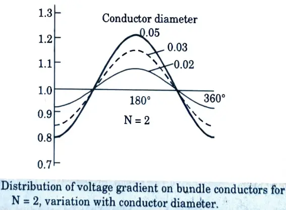
Q8. Explain surface voltage gradient in conductor.
Ans. The surface voltage gradient on conductors in a bundle influences corona production on the line, which has major effects like as auditory noise and radio interference. They also interfere with carrier communication and signalling on the line, as well as television reception.
Q9. Sketch graph for distribution of voltage gradient on sub conductor.
Ans.
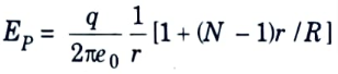
Q10. Give the expression for maximum surface voltage gradient for N ≥ 3.
Ans. In general, for an N-conductor bundle,
Q11. What are the types of vibrations ?
Ans. 1. Aeolian vibrations
2. Galloping
3. Wake induced oscillation
Q12. Define Karman vortices.
Ans. When a conductor is under strain and a rather steady wind blows across it, tiny vortices known as Karman vortices emerge on the leeward side.
Q13. Enumerate factors on which vibrations depend.
Ans.
- 1. Conductor tension
- 2. Span length
- 3. Conductor size
- 4. Type of conductor
- 5. Terrain of line
- 6. Tower type
Unit-II: EHV AC Transmission (Short Question)
Q1. What is meant by ‘corona’ ?
Ans. If the electric field is uniform and steadily raised, just as observable ionization begins, the ionization leads to complete gap breakdown. However, in non-uniform fields, multiple manifestations in the form of visual and aural discharges occur prior to the spark or disintegration of the medium. Corona discharges are what these discharges are called.
Q2. What are the types of corona discharges ?
Ans. Types of corona discharges:
- 1. Grow or pulseless corona
- 2. Pulse type or streamer corona
Q3. Give the effect of corona.
Ans. Deterioration of solid and liquid insulations caused by partial discharges in gaseous spaces. Electrical energy or power loss from transmission-line conductors. This is referred to as corona power loss.
Q4. Give corona loss formula.
Ans. Peek’s expression for the loss in kW/km is with V and V0 in kV.

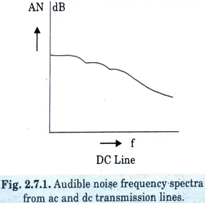
Q5. Discuss audible noise generation.
Ans. EHV lines emit loud noise when corona is present on the conductors, which is especially noticeable during bad weather. The noise is broadband, ranging from very low frequencies to around 20 kHz.
Q6. Show the diagram for audible noise in AC transmission.
Ans.
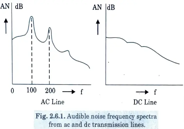
Q7. Sketch the graph for audible noise in DC transmission.
Ans.
Q8. Give the limits of audible noise.
Ans. No complaints: Less than 52.5 dB(A)
Few complaints: 52.5 dB (A) to 59 dB(A)
Many complaints: Greater than 59 dB(A)
The symbol (A) stands for A-weighting network.
Q9. What do you understand by ‘Radio Interference’ ?
Ans. Corona’s negative effect on wireless broadcasting is radio interference. Corona discharges generate radiation that can cause noise in communication links, radio and television receivers. It is mostly caused by brush discharges on the conductor’s surface imperfections during positive half cycles. Corona loss occurs at voltages lower than the critical voltage. Negative discharges are less disruptive to radio reception. Radio interference is defined as a field measured in microvolts per metre at any distance from the transmission line and is only noticeable at levels above 200 kV. The RI level gradually rises until the voltage is such that detectable corona loss occurs. The RI level rapidly increases over this voltage. Smooth and big diameter conductors have a faster rate of growth. The amplitude of the RI level varies inversely with the frequency of measurement. As a result, services in the higher frequency band, such as television, frequency modulated transmission, microwave relay, radar, and so on, are less impacted. Radio interference is a critical consideration while planning a transmission line.
Q10. Give the methods of reduction of switching surges on EHV system.
Ans.
- 1. Drawing of trapped charge of line.
- 2. Series resistance switching.
- 3. Electronic sensing of voltage polarities.
- 4. Limiting value of minimum switching surge.
Q11. What do you mean by psycho acoustic problem ?
Ans. Excessive audible noise emanates from overhead h.v. lines. The noise may disturb nearby residents. Residents tend to lose sleep since the noise is present even at night when ambient noises are very low or non-existent, giving birth to a tendency for insanity. The psycho acoustics problem is the name given to this difficulty or circumstance.
Q12. Give methods to control overvoltage due to switching.
Ans. 1. Energization of transmission lines in one or more steps by inserting resistances and withdrawing them afterwards.
2. Phase controlled closing of circuit breakers.
3. Drainage of trapped charges before reclosing.
4. Use of shunt reactors.
Q13. What are the causes for power frequency overvoltage?
Ans. 1. Sudden loss of loads.
2. Disconnection of inductive loads or connection of capacitive loads.
3. Ferranti effect, unsymmetrical faults.
4. Saturation in transformers.
Q14. Give disadvantages of corona.
Ans. There is a power loss due to corona effect in transmission lines, which increases drastically in foul weather condition. Due to corona, triple frequency current flows through ground in grounded system giving rise to voltage of triple frequency in an ungrounded system. These triple frequency voltages and currents interfere with the communication circuits due to electrostatic and electromagnetic effects.
Q15. Give advantages of corona.
Ans. When a line is switched or charged for a brief period of time, an extremely high voltage flows through it. Corona decreases the size of the high voltage by dissipating some power as corona loss, effectively acting as a safety value.
Q16. What are the factors affecting corona ?
Ans. 1. Frequency.
2. System voltage.
3. Conductor diameter.
4. Load current.
Unit-III: Extra High Voltage Testing (Short Question)
Q1. What are the types of sources required to perform tests on equipment in a high voltage laboratory?
Ans. These are:
- 1. Power-frequency transformers with symmetrical voltages in the two half-cycle without waveshape distortion.
- 2. Impulse generators for lightning-surge waveshape of voltages.
- 3. Impulse generators for switching-surge waveshape of voltages.
- 4. Impulse generators for lightning waveshape of current.
- 5. D.C. generators for some million volts for insulation testing.
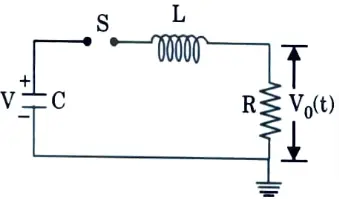
Q2. Draw circuits for producing impulse waves.
Ans.
Q3. Give equation for lightning over voltage.
Ans. Lightning over voltage wave can be represented by double exponential waves defined by the equation
V = V0 [exp (- 𝛂t) – exp(-βt)]
where 𝛂 and β are constants of microsecond values.
Q4. Draw impulse voltage waveform.
Ans.
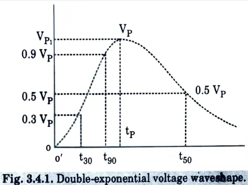
Q5. Define front time.
Ans. Wave-front time : tf = 1.67(t90-t30)
t90 = time from o’ to 90% of peak value = 0.9 Vp,
and t30 = time from o’ to 30% peak value = 0.3Vp.
Q6. Define tail time.
Ans. Wave-tail time: tt = time from o’ to 50% of the peak on the falling portion of the vo>tage wave.
Q7. Enumerate methods to generate high DC voltage.
Ans. 1. Half wave rectifier circuit.
2. Cockroft and Walton circuit.
3. Van-de-Graaf Generator.
Q8. Give the name of methods to measure high voltages.
Ans. 1. Sphere gap.
2. Potential divider.
Q9. What is the steady-state limiting value of electro-static field and radio interference ?
Ans. Electro-static field: Ground level maximum value is 15 kV/m r.m.s.
Radio interference: 40 dB above 1 μV/m at 1 MHz in fair weather at the edge of RoW.
Q10. What do you mean by ‘insulation co-ordination’ ?
Ans. Insulation coordination refers to the relationship between the insulation of various equipments in a power system and the insulation of the protective devices used to safeguard such equipments from overvoltages.
Q11. How the waveshape of impulse voltage can be controlled ?
Ans. The wave-front and wave-tail periods are adjusted by concurrently altering the values of R and L with a given generator capacitance C; selecting an appropriate value for L.
Unit-IV: EHV DO Transmission-I (Short Question)
Q1. Give the classification of DC link.
Ans. DC link is classified as:
- 1. Monopolar link
- 2. Bipolar link
- 3. Homopolar link
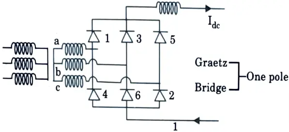
Q2. Enumerate converter configuration.
Ans. 1. 6-pulse Graetz bridge circuit
2. 12-pulse bridge converter
a. Unit 12-pulse converter
b. Double series unit 12-pulse converter
c. Double parallel unit 12-pulse converter
Q3. What are the effects of source inductance on operation of converter ?
Ans. The effect of the input source inductance at the output terminals is a loss of mean voltage as well as a modification to the harmonic distortion terms, whereas at the input terminals, a slight reduction of displacement factor with respect to the AC source voltage occurs, as well as a modification to the distortion terms in the current waveform.
Q4. Give the connection diagram for the double series unit 12-pulse converter.
Ans.
Q5. Enumerate basic firing scheme.
Ans. 1. Individual phase control (IPC).
2. Equidistant pulse control (EPU).
Q6. Explain individual phase control.
Ans. The key feature of this technique is that the firing pulse production for each phase (or valve) is independent of each other, and the firing pulses are tightly synchronized with the commutation voltages.
Q7. What are the drawbacks of IPC scheme ?
Ans. The main disadvantage of the IPC approach is that it exacerbates the harmonic instability problem, which was observed in systems with low short-circuit ratios (less than 4).
Q8. What are the three variation of equidistant pulse control ?
Ans. There are three variations of the EPC scheme:
- a. Pulse Frequency Control (PEC)
- b. Pulse Period Control
- c. Pulse Phase Control (PPC)
Q9. How problem of harmonic inability can be overcome ?
Ans. a. Changing the harmonic behaviour of the AC network impedance observed by the converter (through synchronous condensers or extra filters for filtering out non-characteristic harmonics).
b. Filters in the control circuit are used to filter out non-characteristic harmonics in the commutation voltages. This can be problematic due to fluctuations in supply frequency, which will increase control delays.
Q10. Explain equidistant pulse control (EPC).
Ans. The firing pulses in this technique are generated in steady state at 1pf intervals using a ring counter. Ainsworth proposed this control system initially, utilizing a phase locked oscillator to generate the firing pulses.
Q11. Define overlap period and overlap angle.
Ans. The overlap period is the time when both the outgoing and incoming thyristors are conducting, and the overlap angle or commutation angle is the angle at which both devices share conduction.
Unit-V: EHV DC Transmission-II (Short Question)
Q1. Enumerate different types of converter faults.
Ans. 1. Commutation failure
2. Arc through
3. Misfire
4. Current extinction
Q2. Discuss fault due to current extinction.
Ans. Current extinction can occur in a valve if the current flowing through it falls below the holding current. This can occur at low bridge current values when any transient can cause current extinction. Overvoltages across the valve can occur as a result of current chopping in an oscillating circuit produced by the smoothing reactor and the DC line capacitance.
Q3. What are the factors which are considered in designing a protection system ?
Ans. Factors which must be considered in designing a protection system are:
- 1. Selectivity
- 2. Sensitivity
- 3. Reliability
- 4. Backup
Q4. Give the factors which causes over voltage in a converter station.
Ans. 1. Disturbance originating on AC side
2. Disturbance originating on DC side
3. Internal faults in converter
Q5. Explain function of smoothing reactors.
Ans. 1. They lower the likelihood of inverter commutation failure induced by dips in the AC voltage at the converter bus.
2. They reduce the rate of rise of direct current in the bridge when the direct voltage of another series connected bridge collapses, preventing subsequent commutation failures in inverters.
Q6. Give the causes of generation of harmonics.
Ans. 1. Telephone interference.
2. Extra power losses and consequent heating in machines and capacitors connected in the system.
3. Overvoltages due to resonance.
Q7. Explain AC filter.
Ans. The role of an AC filter is to eliminate all of the negative consequences induced by waveform distortion, notably telephone interference.
Q8. Classify faults produced by over current.
Ans. i. Internal defects that create large overcurrents yet are extremely rare. Surge current ratings for thyristors must be chosen to tolerate these overcurrents.
ii. Line faults that result in overcurrents of 2 to 3 p.u. These are constrained by present regulation.
iii. Inverter commutation failures can be extremely common. Overcurrents, on the other hand, are modest and are limited by current control. The current reference, however, must be decreased due to continued conduction during commutation failures.
Q9. Give types of multi terminal DC systems (MTDC).
Ans. There are two possible types of MTDC systems:
- i. Series
- ii. Parallel
The parallel MTDC systems can be further subdivided into the following categories:
- i. Radial
- ii. Mesh
Q10. Give the name of controlling methods of MTDC system.
Ans. 1. Current margin method
2. Voltage limiting control
3. Two ACR method
Q11. Give the application of MTDC systems.
Ans. Bulk power transfer from a number of remote generating sites to a number of load locations. When connecting more than two systems, an MTDC system is more flexible and cost-effective than using many two terminal DC lines.
Q12. Explain MTDC system.
Ans. A multi terminal DC (MTDC) system contains more than two converter stations, with some acting as rectifiers and others as inverters.
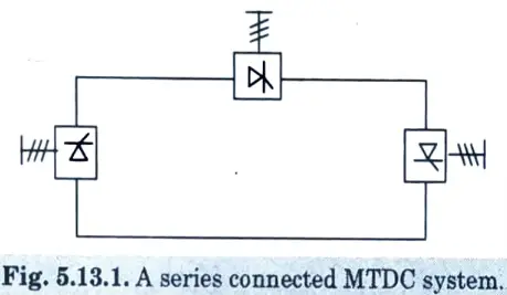
Q13. Draw series MTDC system.
Ans.
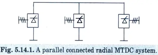
Q14. Draw parallel MTDC system.
Ans.
Q15. Compare series and parallel MTDC system.
Ans.
| S. No. | Series MTDC System | Parallel MTDC System |
| 1. | High speed reversal of power is possible in series systems. | High speed reversal is not possible in parallel systems. |
| 2. | The valve voltage rating is related to power. | Current rating is related to power rating. |
| 3. | Losses are high. | Losses are less in comparison with series system. |

HVDC and AC Transmission Btech Quantum PDF, Syllabus, Important Questions
| Label | Link |
|---|---|
| Subject Syllabus | Syllabus |
| Short Questions | Short-question |
| Question paper – 2021-22 | 2021-22 |
HVDC and AC Transmission Quantum PDF | AKTU Quantum PDF:
| Quantum Series | Links |
| Quantum -2022-23 | 2022-23 |
AKTU Important Links | Btech Syllabus
| Link Name | Links |
|---|---|
| Btech AKTU Circulars | Links |
| Btech AKTU Syllabus | Links |
| Btech AKTU Student Dashboard | Student Dashboard |
| AKTU RESULT (One View) | Student Result |