HVDC and AC Transmission: AKTU Solved Question Paper provides full test preparation aids. These answers to the questions aid in conceptual comprehension, problem-solving practise, and topic selection for the optimum exam preparation.
Dudes 🤔.. You want more useful details regarding this subject. Please keep in mind this as well.

Important Questions For HVDC and AC Transmission:
*Quantum          *B.tech-Syllabus
*Circulars           *B.tech AKTU RESULT
* Btech 4th Year
Section A: Short Question HVDC and AC Transmission
a. Explain necessity of EHVAC transmission.
Ans.
- 1. The transmission efficiency increases as the transmission voltage increases for a given quantity of power transmitted over a given distance.
- 2. The P.U. resistance drop and volume of conductor material decrease in EHV voltage lines.
- 3. The transmission line’s power transmitting capacity grows dramatically in the EHV range because transmission capacity is proportional to the square of the operating voltages.
- 4. The costs of the tower, insulation, and terminal equipment rise, but these expenses are often proportionate to the voltages rather than the square of the voltage.
b. What do you understand by standard transmission voltage?
Ans.
- 1. There are five broad divisions in naming the voltage levels, based on their range of values,
- 2. In AC power transmission when we refer to voltage of the system, it means the effective value or rms value between conductors.
- 3. All AC high voltage transmission takes place by the 3-phase configuration where the line-to-line or conductor-to-conductor voltage is √3 times the voltage between a conductor and the neutral, which is usually called ground.
- 4. These five broad divisions of voltage are :
- L.V. (Low Voltage): Below 11 kV
- M.V. (Medium Voltage): 22 kV, 33 kV, 66 kV
- H. V. (High Voltage): 132 kV, 169 kV, 220 kV, 275 kV
- E.H.V.(Extra High Voltage): 345 kV, 400 kV, 500 kV, 750 kV
- U.H.V. (Ultra High Voltage): 1000 kV, 1150 kV, 1300 kV, 1500 kV
c. Write down corona loss formula.
Ans. Peek’s expression for the loss in kW/km is with V and V0 in kV.

d. Explain principle of half wave transmission.
Ans.
- 1. The half-wavelength line directly reflects its load impedance.
- 2. The input impedance of a half-wave transformer must be equal to the impedance of the load placed at the far end of the half-wave line.
- 3. This attribute is frequency dependent but independent of the characteristic impedance of this line.
- 4. It is not always possible to directly measure the impedance of a load.
- 5. The impedance can be measured along a transmission line linked to the load at a half-wavelength (or an even number of half-wavelengths) distance from the load.
e. What are the necessities of high voltage testing ?
Ans.
- 1. To check whether they are as per the design and as per specifications and standards.
- 2. To ensure that the HV equipment is able to withstand over voltages produced naturally or within the system.
f. What is disruptive discharge voltage ?
Ans. The voltage that produces loss of dielectric strength of equipment is called disruptive discharge voltage.
g. Explain principle of DC link control.
Ans.
- 1. Power control in a DC link can be accomplished by current or voltage control.
- 2. In order to minimise loss, it is critical to maintain constant voltage in the connection and regulate the current to meet the required power. This method is also beneficial for voltage regulation in the system due to the optimal utilisation of the insulation.
- 3. It should be noted that the voltage drop along a DC line is minor in comparison to an AC line, owing to the absence of reactive voltage loss.
h. What is firing angle control ?
Ans.
- i. In this scheme, a voltage controlled oscillator (VCO) is used, the frequency of which is determined by the control voltage V, which is related to the error in the quantity (current, extinction angle of DC voltage) being regulated.
- ii. The frequency in steady-state operation is equal of pf0 where f0 is the nominal frequency of the AC system. PFC system has an integral characteristic and has to be used along with a feedback control system for stabilization.
i. What type of insulation is preferred for DC smoothing reactors ?
Ans. Oil is preferred for DC smoothing reactors.
j. Write down application of MTDC.
Ans. Bulk power transmission from a number of remote generating units to a number of load centres. For connecting more than two systems, an MTDC system is more flexible and cost-effective than using many two terminal DC lines.
Section B: Long Question of HVDC and AC Transmission
a. Explain the technical and economical reasons for adopting EHV transmission system for transfer of bulk power over long distance.
Ans. 1. The transmission efficiency increases as the transmission voltage increases for a given quantity of power transmitted over a given distance.
2. The P.U. resistance drop and volume of conductor material decrease in EHV voltage lines.
3. The transmission line’s power transmitting capacity grows dramatically in the EHV range because transmission capacity is proportional to the square of the operating voltages.
4. The costs of the tower, insulation, and terminal equipment rise, but these expenses are often proportionate to the voltages rather than the square of the voltage.
5. As voltage increases, the overall capital cost of gearbox lowers. Large power transmission blocks are thus economically possible at EHV.
6. Due to economic concerns, huge capacity power plants have been built, necessitating the installation of related transmission lines to evacuate bulk power. While bulk power transmission is economically feasible in the EHV range, larger voltage ranges of operation have made it possible to achieve economies in generating as well.
7. The installation cost of the transmission line per km decreases with increase in voltage level.
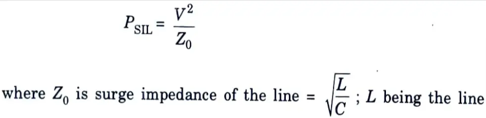
8. For a transmission line, the surge impedance loading (PSIL) is given by

inductance and C the capacitance per unit length. It is evident that as the SIL is proportional to the square of voltage, hence with increase of voltage level, SIL itself increases which indicates that power transfer increases.
9. It is practically not possible to have inter-connections of the power systems on a large scale without EHV transmission.
b. Two generator rated 250 MW and 500 MW are operating in parallel. The drop characteristics of the governors are 4% and 5 % respectively. How would a load of 750 MW be shared between them ? What will be the system frequency ? Take nominal frequency is 60 Hz.
Ans. Given: P1 = 250 MW, P2 = 500 MW, D1 = 4 %, D2 = 5%, P = 750 MW, fnominal = 60 Hz
To Find: Load on generator l and 2, system frequency.
1. For generator 1 :
P(rated) = 250 MW and the drooping characteristics = 4 %
2. For generator 2 :
P (rated) = 500 MW and the drooping characteristics =5 %
3. Both the generators are operating at 60 Hz.
4. A load of 750 MW has to be shared between generator 1 and generator 2. So, let the load on generator 1 be ‘x’ MW and on generator 2 be (750 – x) MW.
5. Reduction in frequency,
∆f for generator 1 = (0.04 x 60/250) x x ….(1)
6. Reduction in frequency,
∆f for generator 2 = (0.05 x 60/500) x (750 – x) ….(2)
7. Equating the value for ∆f from eq. (1) and eq. (2), we get
[0.04 x 60/250] x x= (0.05 x 60/500] x (750 -x)
or 0.0096 x= 0.006 x (750 x)
0.0096 x= 4.50.006 x
0.0156 x = 4.5
x = 288.46 MW = Load on generator 1
Load on generator 2 = 750 – 288.46 = 461.54 MW
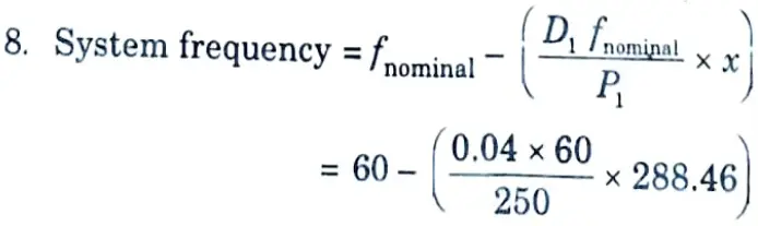
= 60 – 2.76 = 57.24 Hz
c. Explain design factors for EHV lines under steady state limits.
Ans. Design factors of EHV lines under steady state are as follows :
1. The limits for maximum operating voltages are as follows :
Nominal system kV 220 345 400 500 735-765 1000 1150
Maximum 245 362 420 525 765 1050 1200
equipment kV
2. Electrostatic field: The horizontal and vertical components of field are determined at a point A(r, y) where x and y are its coordinates with reference to a chosen origin. A convenient location is at ground under the centre phase. Then :
i. Vertical component due to phase i will be
Ev(i) = (qi/2𝝅e0).[(Hi – y) / Di2 + (Hi + y) / (Di’)2]
ii. Horizontal component is
Eh(i) = (qi/2𝝅e0) (x – xi) [1/Di2 – 1/(Di’)2]
where, xi = horizontal coordinate of phase i,
Di2 = (x – xi)2 +(y – H)2
and (D’i)2 = (x – xi)2 + (y + Hi)2
iii. The total field is
Ei2 = [Σ Ev (i)]2 + [Σ Eh (i)]2
3. Conductor surface voltage gradient: The maximum surface voltage gradient on any sub-conductor will be
Emax = (qi /2𝝅e0) . (1/N).(1/r) [1 + (N – 1)r /R)
For most practical calculation, the Mangoldt Formula (Market-Mengele Formula) can be used for horizontal configuration of the three phases.
4. Corona-inception gradient: For a cylindrical conductor above a ground plane, Peek’s formula for corona-inception gradient is

where m = conductor surface roughness factor < 1
r = conductor radius in metre
b = barometric pressure in millibars
t = temperature °C
t0 = reference temperature, 20°C presently used, but will become 27°C when adopted in future.
5. Radio noise level: For upto 4 conductors in bundle, the C.IG.R.E formula is
RI(k) = 0.035 Em (k) + 1200 r – 33 log (D (k)/20) – 30 dB
where, Em (k) = maximum surface voltage gradient on sub-conductor in kV/m r.m.s.
Audible noise : For N < 3, AN(A) = 120 log Em (k) + 55 log (2r) – 11.4 log D(k) – 245.4 dB(A)
For N ≥ 3, AN(k) = 120 log Em (k) + 55 log (2r) – 11.4 log D(A) + 26.4 log N- 258.4 dB(A)
The total AN level of the 3 phases is
6. Corona loss: (Ryan and Henline formula)
WL = 4fC V(V – V0) MW/km 3-phase
7. Voltage control at power frequency :
Line only :
Z = (r + jω) L, V1 = jωCL.
r, L, C = distributed resistance, inductance and capacitance per km
ω = 2𝛑f
d. What are the benefits of using FACTS devices ? Give the type of FACTS controllers and quantities/parameters being controlled by these.
Ans. A. Advantages of FACTS devices :
- 1. It enhances controllability.
- 2. It increases power transfer capability of the network.
- 3. It increases the reliability of AC grids and reduces power delivery costs.
- 4. The improve transmission quality and efficiency of power transmission by supplying inductive and reactive power to the grid.
B. Types of FACTS controller :
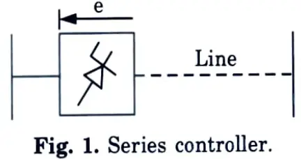
a. Series controller :
- 1. Series controllers inject a voltage in series with the line. As long as the voltage is in phase quadrature with the line current, series controller supplies reactive power only.
- 2. Series controller controls the current/power flow and damp oscillation.
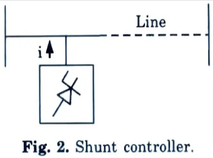
b. Shunt controllers :
- 1. Shunt controllers, may be variable impedance, variable sources or a combination of these.
- 2. Shunt controller inject current into the system at the point of connection.
- 3. Shunt controller is good to control the voltage at and ground the point of connection through injection of reactive current (leading/ lagging).
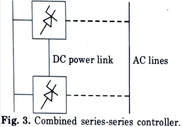
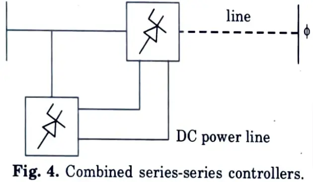
c. Combined series-series controllers: It could be a combination of separate series controllers, which are controlled in a coordinated manner, in a multi-line transmission system.
d. Combined series-shunt controllers :
- 1. This could be a combination of separate shunt and series controller, which are controlled in a coordinated manner or a unified power flow controller (UPFC) with series and shunt elements.
- 2. UPFC can provide effective current / power control along with voltage control.
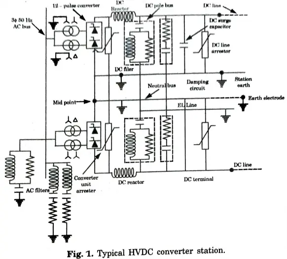
e. Draw a simple scheme of HVDC converter station and describe briefly components of the converter station.
Ans. A. Converter station :
- 1. The terminal substations which convert an AC to DC are called rectifier terminal while the terminal substations which convert DC to AC are called inverter terminal.
- 2. Every terminal is designed to work in both the rectifier and inverter mode. 3. Therefore, each terminal is called converter terminal, or rectifier terminal. A two-terminal HVDC system has only two terminals and one HVDC line.
B. Converter unit :
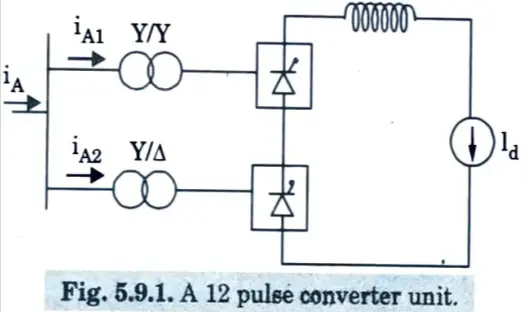
- 1. Three-phase bridge converters are used in HVDC converter stations to convert AC to DC and vice versa. The Graetz circuit is another name for this bridge circuit.
- 2. A 12-pulse bridge converter is employed in HVDC transmission. By connecting two or six-pulse bridges in sequence, the converter is created.
C. Converter valves :
- 1. 12-pulse converter units are used in current HVDC converters. Each unit contains a total of 12 valves. The valve is made up of thyristor modules that are connected in series.
- 2. The number of thyristor valves required is determined by the required voltage across the valve.
- 3. The valves are mounted in valve halls and cooled by air, oil, water, or freon, using a 12-pulse converter unit.
D. Converter transformer :
- 1. The converter transformer transforms alternating current networks to direct current networks or vice versa. They have two three-phase winding sets. The AC bus bar is connected to the AC side winding, and the valve bridge is connected to the valve bridge.
- 2. These windings are connected in a star configuration for one transformer and a delta configuration for another.
- 3. The two three-phase transformer’s alternating current side windings are connected in stars, with their neutrals grounded.
E. Filters :
- 1. The AC and DC harmonics are generated in HVDC converters. The AC harmonics are injected into the AC system, and the DC harmonics are injected into DC lines.
- 2. The harmonics are minimised by using the AC, DC and high frequency filters. The types of filter are explained below in details :
- i. AC Filters :
- a. The AC filters are connected to the phase and earth through an RLC circuit. They provided harmonic frequencies with low impedances.
- b. The alternating current harmonic currents are thus transferred to earth. Filters that are tuned and damped are employed.
- c. The AC harmonic filter also provided the reactive power required for the converters to operate properly.
- ii. DC Filters :
- a. The DC filter is connected between the pole bus and neutral bus.
- b. It diverts the DC harmonics to earth and prevents them from entering DC lines.
- c. Such a filter does not require reactive power as DC line does not require DC power.
- iii. High-Frequency Filters :
- a. The HVDC converter may generate electrical noise in the 20–490 kHz carrier frequency region.
- b. They also produce radio interference noise in the megahertz band. To reduce noise and interference with power line carrier communication, high-frequency filters are used.
- c. These filters are installed between the converter transformer and the station’s alternating current bus.
F. Reactive power source :
- 1. Reactive power is necessary for the converters to operate. The reactive power is provided in part by the AC harmonic filters.
- 2. Shunt capacitors, synchronous phase modifiers, and static VAr systems can also provide additional power. The option is determined by the desired speed of control.
G. Smoothing reactor :
- 1. Smoothing reactors are oil-filled, oil-cooled reactors with a high inductance. It is connected to the converter in series before the DC filter. It can be situated on either the line or neutral side.
- 2. Smoothing reactors serve the following purpose :
- i. They smooth the ripples in the direct current.
- ii. They decrease the harmonic voltage and current in the DC Iines.
- iii. They limit the fault current in the DC line.
H. HVDC system pole :
- 1. The HVDC system pole is a component of an HVDC system that includes all of the equipment in the HVDC substation. It also connects transmission lines that, under normal working conditions, have a common direct polarity with regard to the earth.
- 2. Therefore, the term pole refers to the route of DC that has the same polarity as the earth. The entire pole consists of the substation pole and the transmission line pole.
Section 3: Discussed Questions of HVDC and AC Transmission
a. Explain UHV AC transmission system.
Ans.
- 1. The current tendency is to transfer enormous amounts of electricity through medium and long lines at extremely high voltages (over 300 kV), and the rms values of these voltages are referred to as “Extremely High Voltage.”
- 2. The voltages whose values exceed 750 kV are termed as “Ultra High Voltages” (UHV).
- 3. Generally almost all aspects of characteristics and operations of EHV lines are applicable to UHV lines :
- a. Extra High Voltage (EHV) AC gearbox may be considered to have reached maturity in 1952, when the first 380-400 kV line was installed in Sweden.
- b. Since then, developed countries around the world have embraced this and greater voltage levels.
- 4. In our country the first 400 kV transmission line from Obra to Sultanpur and 400 kV substation at Sultanpur (UP) was commissioned in December, 1977.
- 5. The single serious problem encountered with EHV voltage level is the over voltages during switching operations, commonly called switching surge over voltages :
- a. High DC voltages are used in industry, research, and medical sciences, among other things. HVDC transmission using overhead lines and underground cables is gaining popularity.
- b. In 1954, the world’s first commercially used High Voltage DC (HVDC) link of 20 MW, 100 kV capacity was created between Sweden’s mainland and the island of Gotland.
- c. Since then the technique of power transmission by HVDC has been continuously developed.
The need of operation of transmission lines in the EHV range are mostly due to following reasons:
- 1. The transmission efficiency increases as the transmission voltage increases for a given quantity of power transmitted over a given distance.
- 2. The P.U. resistance drop and volume of conductor material decrease in EHV voltage lines.
- 3. The transmission line’s power transmitting capacity grows dramatically in the EHV range because transmission capacity is proportional to the square of the operating voltages.
- 4. The costs of the tower, insulation, and terminal equipment rise, but these expenses are often proportionate to the voltages rather than the square of the voltage.
- 5. As voltage increases, the overall capital cost of gearbox lowers. Large power transmission blocks are thus economically possible at EHV.
- 6. Due to economic concerns, huge capacity power plants have been built, necessitating the installation of related transmission lines to evacuate bulk power. While bulk power transmission is economically feasible in the EHV range, larger voltage ranges of operation have made it possible to achieve economies in generating as well.
- 7. The installation cost of the transmission line per km decreases with increase in voltage level.
- 8. For a transmission line, the surge impedance loading (PSIL) is given by
inductance and C the capacitance per unit length. It is evident that as the SIL is proportional to the square of voltage, hence with increase of voltage level, SIL itself increases which indicates that power transfer increases.
9. It is practically not possible to have inter-connections of the power systems on a large scale without EHV transmission.
b. Illustrate the power handling capacity and line loss of EHVAC lines with various voltage levels.
Ans. 1. The power-handling capacity of a single circuit is P = E2 sin δ/Lx.
2. At unity power factor, at the load P, the current flowing is

and the total power loss in the 3-phases will amount to
p = 3I2rL = E2 sin2 δ.r/Lx2 …(2)
3. Therefore, the percentage power loss is
%p = 100 p/P = 100. sin δ. (r/x) …(3)
4. Table 1 shows the percentage power loss and power-handling capacity of lines at various voltage levels, for δ = 30°and without series-capacitor compensation.
Table 1. Percent power loss and power-handling capacity
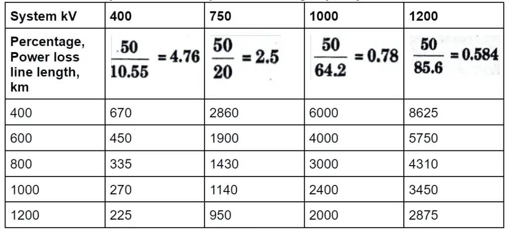
5. The following important and useful conclusions can be drawn for preliminary understanding of trends relating to power-handling capacity of AC transmission lines and line losses:
- i. One 750 kV line can normally carry as much power as four 400 kV circuits for equal distance of transmission.
- ii. For the same transmission distance, one 1200 kV circuit can transmit the power of three 750 kV circuits and twelve 400 kV circuits.
- iii. At a fixed voltage level, the power-handling capability of a line diminishes with line length, and is inversely proportional to line length L.
- iv. Based on the foregoing fact, we can conclude that if conductor size is determined by current rating, as line length rises, lower conductor sizes will be required. This increases the risk of high voltage effects induced by reduced conductor diameters, which causes corona on the conductors and intensifies radio interference levels, audible noise, and corona loss.
- v. However, the percentage power loss in transmission remains independent of line length since it depends on the ratio of conductor resistance to the positive-sequence reactance per unit length, and the phase difference δ between Es and Er.
Section 4: Question, Notes of HVDC and AC Transmission
a. Write short notes on :
i. Radio interference effects on EHVAC.
ii. Ferro-resonance.
Ans. i. Radio interference effects on EHVAC :
- 1. Radio interference is a negative effect of corona on wireless broadcasting.
- 2. Corona discharges generate radiation that can cause noise in communication links, radio and television receivers.
- 3. It is primarily caused by brush discharges on the conductor’s surface imperfections during positive half cycles.
- 4. Corona loss occurs at voltages lower than the critical voltage.
- 5. Negative discharges are less disruptive to radio reception.
- 6. Radio interference is defined as a field measured in microvolts per metre at any distance from the transmission line and is only noticeable at voltages above 200 kV.
- 7. The RI level gradually increases until the voltage is such that detectable corona loss occurs.
- 8. Above this vóltage there is rapid increase in RI level.
- 9. The rate of increase is more for smooth and large diameter conductors.
- 10. The amplitude of the RI level varies inversely with the frequency of the interference.
- 11. As a result, services in the higher frequency band are less affected, such as television, frequency modulated transmission, microwave relay, radar, and so on.
- 12. Radio interference is one of the very important factors while designing a transmission line.
ii. Ferro-resonance :
- 1. In power systems, partial resonance circumstances occur when an unbalanced setup places capacitances in series with inductances.
- 2. When a transformer is connected to a long transmission line and both are switched together, as shown in Fig., such a circumstance may occur.
- 3. Under normal operating conditions, the line capacitance to ground is energized by the phase voltage.
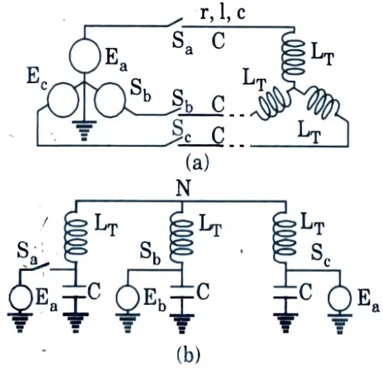
- 4. But, imagine that during a switching operation, one pole opens or closes independently of the others. The equivalent circuit demonstrates that in the open phase, the line capacitance is in series with the transformer inductances.
- 5. Fig. shows the circumstance when two poles are open. The problem necessitates a complicated analysis that takes into account the dispersed capacitance of the line as well as the transformer’s non-linear magnetization curve.
b. Explain generation and characteristics of corona pulses for EHVAC transmission.
Ans. 1. There are in general two types of corona discharge from transmission-line conductors :
i. Pulseless or glow corona;
ii. Pulse type or streamer corona.
2. Both these give rise to energy loss, but only the pulse-type of corona gives interference to radio broadcast in the range of 0.5 MHz to 1.6 MHz.
3. Spark discharges from chipped or damaged insulators and loose guy wires, in addition to corona formed on line conductors, interfere with TV reception in the 80-200 MHz range.
4. Corona on conductors also interferes with carrier communication and signalling in the 30 kHz to 500 kHz frequency range.
5. In space, which contains extremely few starting electrons, free electrons and charged particles (ions) are generated, as in most gas discharge processes under high impressed electric fields.
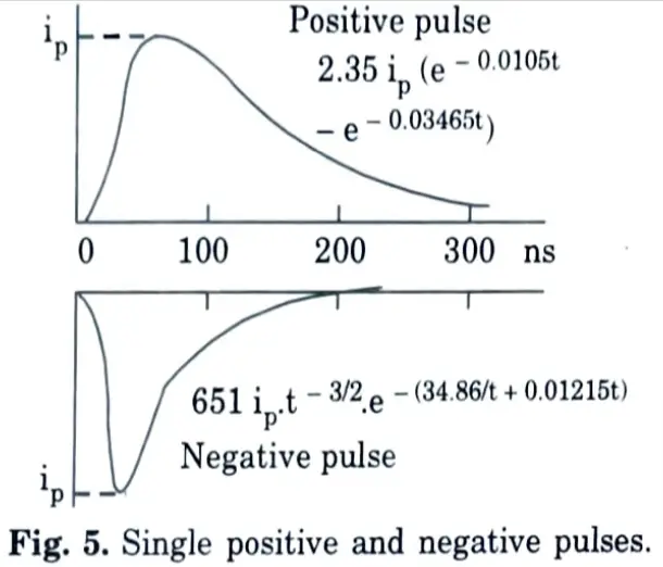
6. As a result of the avalanche mechanism and their travel towards the proper electrode, we can expect a building of resultant current in the conductor from zero to a maximum or peak.
7. As the peak value is attained, current decreases due to a decrease in the electric field caused by the relatively heavy stationary space charge cloud, which reduces ion velocity.
8. As a result, we can anticipate pulses with short crest times and somewhat extended fall times.
9. The author’s measurements of single pulses in a co-axial cylindrical arrangement are shown in Fig. 5 under DC excitation.
10. Similar pulses occur during the positive and negative half-cycles under AC excitation.
11. The equations that observed wave shapes are also given on the Fig. 5.
12. It will be assumed that positive corona pulses have the equation
i+ = k+ip(e-at -e-βt) ….(1)
while negative pulses can be described by
i– = k–ipt-3/2.e-γ/t-δ/t
13. These equations have formed the basis for calculating the response of bandwidth-limited radio receivers (noise meters), and for formulating mathematical models of the radio-noise problem.
14. In addition to the wave shape of a single pulse, their repetition rate in a train of pulses is also important.
Section 5: HVDC and AC Transmission Related Questions
a. What are the effects of pollution on the performance of EHV lines ?
Ans.
- 1. Pollutants from the environment are deposited on gearbox insulation. The contaminants’ nature is determined by the nature of the environment.
- 2. Pollutants in coastal areas are typically sodium chloride, which is deposited on the insulating surface. If the humidity rises or rain falls, the sodium chloride becomes moist and provides a conduction channel, potentially resulting in a flashover.
- 3. The chemical salts deposited in industrial regions are determined by the type of the enterprise. The moisture absorption capacity of these deposits is affected by relative humidity and environmental circumstances. Some of these deposits can damage the insulator surface by becoming acidic.
- 4. The deposits on the insulator surface become conductive, allowing leakage current to flow over the insulator. Dry bands emerge on the insulator surface as the temperature rises, and the voltage gradient across these bands increases until arcing occurs across the bands. These arcs have the potential to become flashovers.
- 5. Because of the non-uniform pollution distribution along the insulator surface, the equivalent surface conductivity and the difference in hygroscopicity between the top and bottom surfaces diminish, increasing the withstand voltage and decreasing the root mean square value of leakage current.
b. Explain measurement of high voltage by sphere gaps and potential dividers.
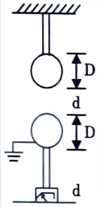
Ans. A. Measurement of high voltage by sphere gaps :
- 1. The gap between two perfect spheres (one charged with high voltage and the other normally grounded) creates a very handy and precise (to 3% tolerance) voltmeter for measuring extremely high DC, AC, and impulsive voltages.
- 2. The general arrangement of a sphere gap with sphere diameter D and gap separation d is shown in Fig.
- 3. An insulated rod fixed to the roof of the laboratory if stationary, or a frame if the sphere gap is to be made portable, supports the h.v. sphere from the top.
- 4. The bottom sphere is also supported by an insulated rod and is equipped with a threaded rod that may be turned to adjust the gap.
- 5. This is carried out either or manually by a remote-controlled motor from the control panel. The gap spacing is indicated on a suitably calibrated meter.
- 6. To evaluate the flashover voltage of a test object, such as an insulator string or bushing with a spill gap (rod-to-plane or rod-to-rod gap), connect the test item in parallel with the sphere gap.
- 7. Assume that the flashover voltage of the test object is close to 500 kV.
- 8. The gap setting of the spheres is selected from the standard calibration table for this voltage.
- 9. If the voltage is steadily increased from the source and the rest object (with resealable insulation) flashes over but not the sphere gap, it is apparent that the test object’s breakdown voltage is less than 500 kV.
- 10. The experiment is repeated with the sphere gap spacing lowered somewhat.
- 11. After a few repetitions, a gap setting is found where both the test object and the sphere gap flashover at the same time. The corresponding voltage is read and adjusted to normal air conditions.
B. Measurement of high voltage by potential dividers :
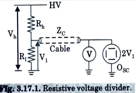
- 1. Two resistors Rh and Rl connected in series between the h.v. terminal and ground. A voltmeter or an oscilloscope is connected across the lower resistor Rl. The voltage applied to the meter is, by voltage division :
- 2. When using a resistive voltage divider to measure high impulse voltages that are not steady like DC or sinusoidal AC, the low-voltage circuit must be given special consideration.
- 3. To examine the complete waveform, an oscilloscope or a special metre known as a “Peak Voltmeter” must be used.
- 4. The l.v. arm’s output is routed through a cable with a characteristic impedance of ZC ohms, which behaves like pure resistance.
- 5. If the instrument end of the wire is linked to an oscilloscope’s vertical deflection plates, the setup acts as an open circuit for the surge.
- 6. As a result, the travelling wave of impulse voltage is completely reflected, and the indication on the oscilloscope screen is twice the magnitude of voltage indicated by the voltage ratio.
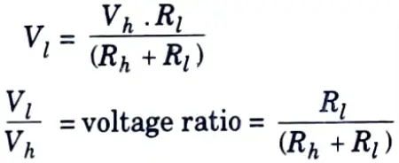
- 7. However, if the cable is terminated at the oscilloscope input terminals by a matching resistor with a value equal to the cable impedance ZC, the voltage indication on the oscilloscope screen will be the same as the voltage across the voltage divider’s l.v. arm.
- 8. Once again, for extremely high voltages, the physical size of the divider is extraordinarily tall (6 to 11 metres in height), resulting in stray capacitance and inductance.
- 9. However, the very high value of the divider resistance will damp out any oscillations that might be present in high-rate-of-rise voltages such as lightning impulses (1.2/50 μs).
- 10. To eliminate inductance, it is usual to construct the high resistance by carbon film and not use wire-wound jobs.
Section 6: HVDC and AC Transmission Important Questions
a. Describe types of HVDC links with the help of diagrams. Discuss the applications of each of these links.
Ans. A. Types of HVDC links :
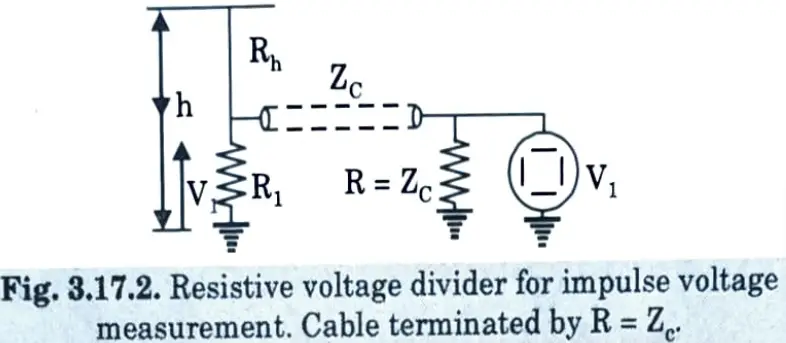
1. Monopolar link: In this setup, only one conductor (typically negative) is employed, and ground or sea water is utilised. Because of the lower radio interference, negative polarity is commonly used as the transmission conductor.
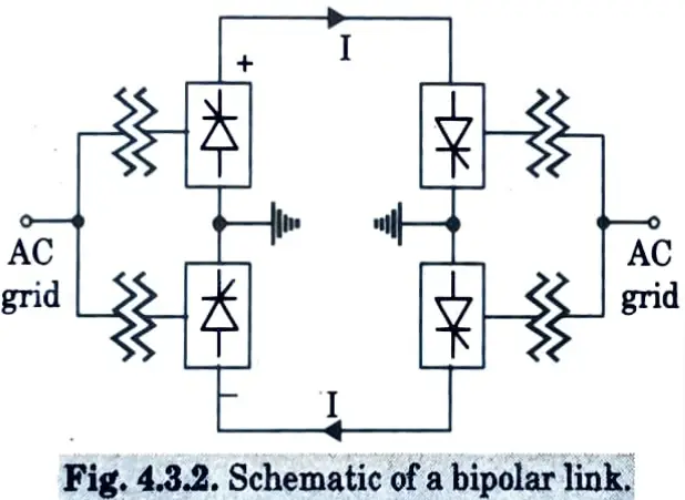
2. Bipolar link :
- 1. There are two conductors in this design, one positive and one negative.
- 2. Two converters with equal rated voltages are connected in series in each terminal, with neutral points grounded. When both neutrals are grounded, two poles can operate independently.
- 3. When the currents in the two conductors are equal, the ground current is zero.
Advantages: In case of a fault in one conductor, the remaining conductor, along with ground return can supply 50 % of the rated load. The rated voltage of a bipolar link is usually expressed as ± V volts.
3. Homopolar link: It has two conductors but having same polarity, usually negative.
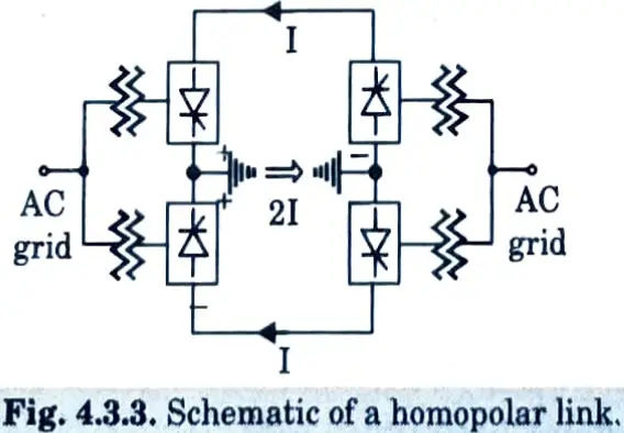
This link operates with ground return. In case of a fault in one conductor the converter can be connected such that the healthy conductor can supply power.
B. Applications of HVDC links :
- 1. Monopolar HVDC link: Monopolar HVDC links are used for low power rating and cable transmission.
- 2. Bipolar HVDC link: Bipolar HVDC link is most widely used DC link for overhead long distance HVDC transmission systems and also for back for back HVDC system.
- 3. Homopolar HVDC link: Homopolar HVDC link is used for the following :
- i. Two homopolar overhead supplying to a common monopolar cable termination.
- ii. One overhead transmission tower carrying insulator strings supporting two homopolar transmission line conductors.
b. Discuss the advantages and disadvantages of HVDC transmission.
Ans. A. Advantages :
- 1. These systems are economical for transmitting bulk power over long distance, say above 550 km.
- 2. Because a DC transmission line has no inherent instability, asynchronous operation of the transmission line in conjunction with the connected machines is conceivable.
- 3. Because there is no charging current in DC gearbox systems, there is no line length limitation. Also, cables in a DC system do not suffer from severe dielectric loss as a result. In addition, because the skin effect is less in DC systems, the current density in the DC transmission line can be higher.
- 4. There is more power transmission per conductor, and the DC line is less expensive because it only requires two conductors rather of three, resulting in lower insulator and tower costs.
- 5. Voltage regulation issues are less severe in a DC system since there is no reactance drop in a DC line at steady state.
- 6. Corona loss in HVDC systems is substantially smaller than in AC systems. HVDC wires also have less radio interference.
- 7. Using a single conductor in HVDC transmission simplifies line construction and allows for ground return.
- 8. DC gearbox has lower line loss.
- 9. Interconnection of AC grids via AC tie lines raises the fault level, whereas interconnection of AC grids via DC links does not raise the fault level as much.
- 10. HVAC lines and HVDC links can be utilised in parallel to improve network transient stability.
- 11. There is easy reversibility and controllability of power flow through an HVDC link.
- 12. Low short circuit current is required on HVDC lines
- 13. During fault in the DCline, grid control of the converter can drastically reduce the fault current.
- 14. Frequently long distance AC transmission lines require shunt compensation. Such compensation is not required in DC lines.
B. Disadvantages :
- 1. The overall cost rises, particularly for lines less than 500 km, due to the added requirements for converters, filters, and reactive power compensators.
- 2. Circuit breaking is difficult and costly in multi-terminal DC systems.
- 3. Converter stations necessitate a large amount of reactive power.
- 4. Harmonic production and subsequent filtration are issues in direct current systems.
- 5. HVDC converters have a poor overload capacity.
- 6. Voltage transformation is only required on the alternating current side.
- 7. Because no reactive power may be sent across an HVDC link, the load’s reactive power must be supplied locally.
- 8. Insulator maintenance in HVDC transmission lines is more expensive.
- 9. The difficulty of breaking DC currents which results in high cost of DC breakers.
- 10. Inability to use transformers to change voltage levels.
- 11. High cost of conversion equipment.
- 12. Generation of harmonics which require AC and DC filters, adding to the cost of converter stations.
- 13. Complexity of control.
Section 7: Solved Questions of HVDC and AC Transmission
a. Explain protection against over currents and over voltages for EHV DC transmission.
Ans. A. Protection against over current :
- 1. The over current protection in converters is based on principles similar to those used in AC systems. The factors that must be considered in designing a protection system are :
- i. Selectivity,
- ii. Sensitivity,
- iii. Reliability and
- iv. Back up.
- 2. The key advantage of converter protection is the ability to clear faults quickly (in less than 20 m/sec) by blocking gate pulses or current regulation and control.
- 3. The high impedances of the smoothing reactor and the converter transformer also improve selectivity.
- 4. Furthermore, the converters are split into independent valve groups, so that the protective system can only turn off the damaged valve group (or bridge).
- 5. Consider a converter station with a 12 pulse converter per pole (2 valve groups per pole). The protection system used for a pole is shown in Fig. This does not show protection against DC line faults, undervoltage or transformer protection.
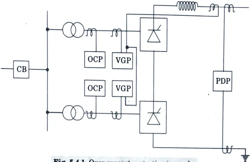
- 6. Valve group differential protection provides the fundamental protection against converter faults by comparing the rectified current on the valve side of the converter transformer to the DC current recorded on the line side of the smoothing reactor.
- 7. Differential protection is used because of its selectivity and speed of detection.
- 8. As a backup, the overcurrent protection circuit is used. To avoid tripping with faults outside the station, the level of overcurrent necessary to trip must be adjusted greater than that of the valve group differential protection (that can be cleared by the control action).
- 9. The pole differential protection detects ground defects that would otherwise go undetected, such as problems on the neutral bus.
- 10. The fault clearing operation of these safety circuits is to close the valves while also tripping the AC breaker of the afflicted group or pole.
- 11. The quick tripping sequence is employed for internal problems where valve damage is possible. This entails using forced retard (raising the rectifier’s delay angle to roughly 150) in conjunction with the signal to trigger the AC breaker.
- 12. After 20 m/sec, the pulses are blocked. This enables the rectifier station’s inverter action (by forced retard) to attempt to lower the current before the converter is blocked.
- 13. The faults producing overcurrent are classified into 3 categories :
- i. Internal defects that create large overcurrents yet are extremely rare. Surge current ratings for thyristors must be chosen to withstand these Excessive currents.
- ii. Line faults that result in overcurrents of 2 to 3 p.u. They are constrained by present regulation.
- iii. Inverter commutation failures can be extremely common. Overcurrents, on the other hand, are modest and are limited by current control. Despite this, the current reference must be decreased due to ongoing conduction during commutation failures.
B. Protection against over voltage :
- 1. The typical arrangement of surge arresters in a converter station (for a pole) is shown in Fig. For a system with two 12-pulse converters per pole, there are about 40 arresters per pole.
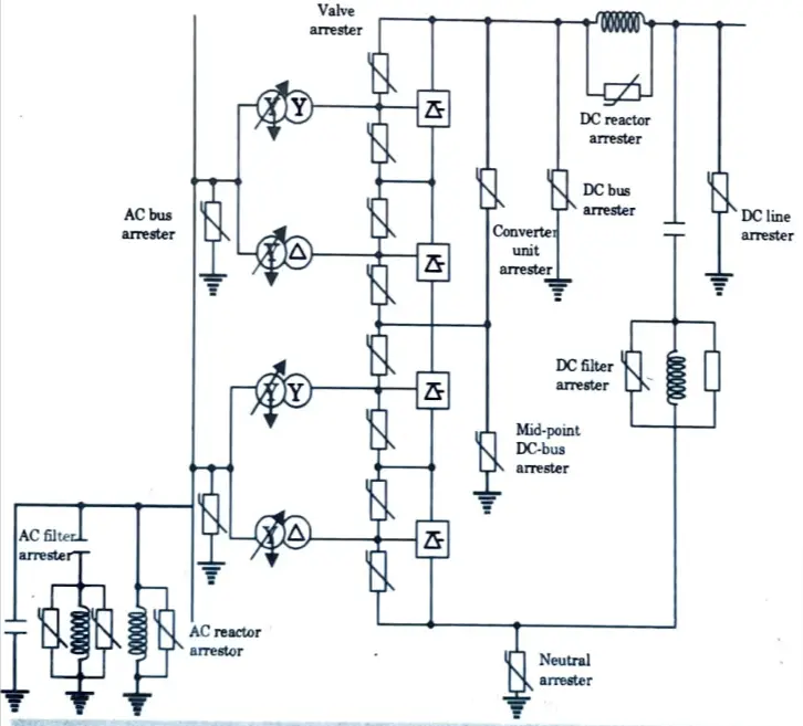
- 2. The arresters are chosen to have suitable energy dissipation capabilities, which vary depending on their placement.
- 3. For example, when a ground fault arises between the valve and the converter transformer in the upper bridge, the valve arrester protecting the commutation group at the highest potential can be subjected to larger energies than other arresters. This is related to the line and DC filter discharge.
- 4. Closing a bypass switch across a converter causes the DC voltage across the remaining converter to rise. In such instances, the converter unit arrester is emphasised.
- 5. The protective firing of a valve is the backup protection offered for forward voltage overvoltages.
b. Write short notes on:
i. Generation of harmonics of EHV DC.
ii. AC and DC filters.
Ans. A. Generation of harmonics :
1. The characteristic harmonics are harmonics which are always present even under ideal operation balanced AC voltages, symmetric three phase network and equidistant pulses.
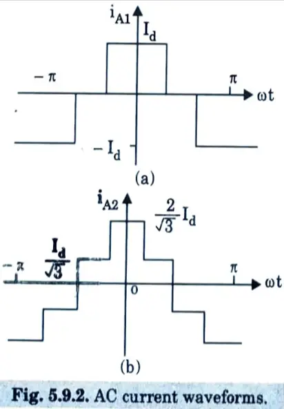
2. In the converter analysis the DC current is assumed to be constant. In this case, there are harmonics in AC current of the order
h = np ± 1 …(5.9.1)
where p is the pulse number, n is any integer. The harmonics in the converter DC voltage are of the order
h = np …(5.9.2)
4. When the smoothing reactor is of finite impedance, there are harmonics in the DC currents also of the order given by eg (5.9.2).
5. The AC current harmonics, in this case, are still of the order defined in eg. (5.9.1), although their magnitudes will be different with the presence of the ripple in DC current.
B. AC filters :
- 1. The role of AC filter is to eliminate all the detrimental effects caused by waveform distortion and particularly the telephone interference.
- 2. Harmonic voltage is also to be low and for this the following factors are considered for assessing the voltage distortion :
- i. Individual harmonics
- ii. The total voltage distortion and
- iii. Telephonic interference
- 3. The filter size and quality are two fundamental aspects in filter design. The reactive power supplied by a filter at fundamental frequency is defined as its size.
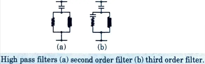
- 4. The sharpness of tuning expressed by a filter’s quality improves with the ratio of its resonance for resonant filters. Sharpness increases in inverse proportion to ratio when using a high pass filter.
- 5. The early DC methods used just shunt harmonic tuned filters, which were made up of a series PLC circuit tuned to the frequency of a low characteristic harmonic.
- 6. The filter quality is chosen to achieve optimal filter operation, i.e., the chosen value should inject the least amount of harmonic current into the network for the assumed operating situation.
- 7. A larger Q reduces the filter losses and the harmonic voltage, but it increases the risk of parallel resonance between the filters and the network. Fig. represents typical AC filters in HVDC installations.
DC filter :
- 1. Harmonic voltages on the DC side of a converter station cause AC currents in the transmission line to be superimposed on the direct current.
- 2. Despite smoothing reactors, these higher frequency alternating currents can cause interference in neighbouring telephone networks.
- 3. DC filter circuits linked in parallel to the station poles are an effective instrument for dealing with these issues. The DC filter arrangement is quite similar to the filters on the AC side of the HVDC station.
- 4. There are various filter designs. Single and multiple-tuned filters with or without a high-pass function are widely used. A converter station may employ one or more types of DC filters.
2 thoughts on “HVDC and AC Transmission: AKTU Solved Question Paper”