
In this Blog, We are discussing the Last year question paper of Fluid Mechanics & Fluid Machines AKTU, Year -2022-23. Hope this important Questions will help you in your upcoming Fluid Mechanics & Fluid Machines exams.
Dudes 🤔.. You want more useful details regarding this subject. Please keep in mind this as well.

Important Questions For Fluid Mechanics & Fluid Machines :
*Unit-01     *Unit-02
*Unit-03    *Unit-04
*Unit-05    *Short-Q/Ans
*Question-Paper with solution 21-22
Section A: Short Question in Fluid Mechanics & Fluid Machines AKTU
a. Define ideal fluid.
Ans. An ideal fluid is one that cannot be compressed and has no viscosity.
b. Describe capillary rise.
Ans. Capillary rise is the rise of a liquid surface inside a tiny tube compared to the surrounding liquid’s general level while the tube is held vertically in the liquid.
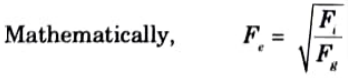
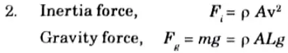
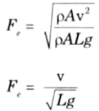
c. Define Froude’s number.
Ans. 1. It is the square root of the ratio of inertia force to the gravity force of
a flowing fluid. It is denoted by Fe.
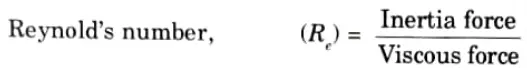
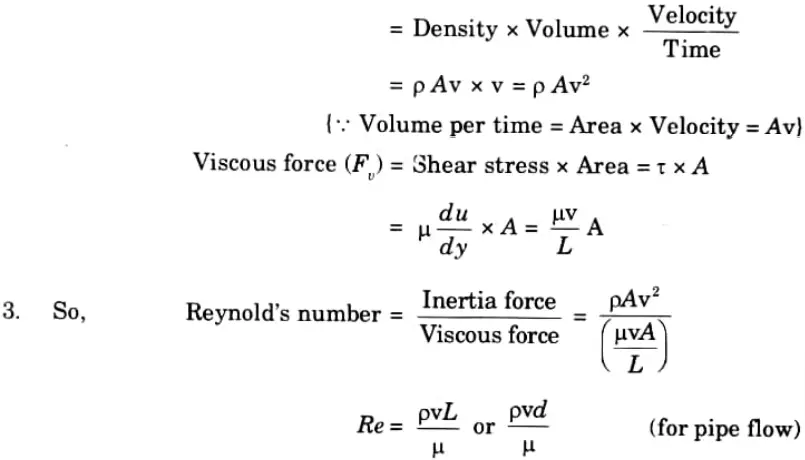
d. Describe the significance of Reynold’s number.
Ans. 1. It is defined as the ratio of the inertia force to the viscous force.
Inertia force = Mass x Acceleration
e. Explain eddy viscosity.
Ans Eddy viscosity is the viscosity that controls how momentum is transported by turbulent eddies.
f. Define laminar sub layer.
Ans. Laminar Sub Layer: This is the area of the boundary layer zone that is close to the plate’s solid surface.
g. Define unit power for a turbine.
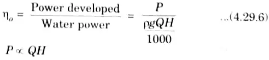
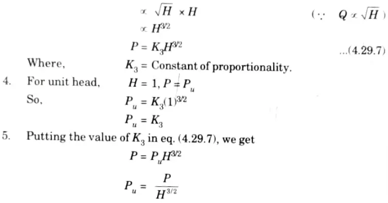
Ans. 1. It is defined as the power developed by a turbine, working under a unit head. It is represented by symbol Pu
2. let, P = Power developed by the turbine under head H.
3. Overall efficiency is given as,
h. Explain the function of penstock in a hydroelectric ·power plant.
Ans Penstocks, which are large-diameter pipes used to transport water from storage reservoirs to the turbine, are often composed of steel or reinforced concrete.
i. Define a pump.
Ans: Pumps boost the fluid’s energy by converting mechanical energy into hydraulic energy.
j. Describe the slip of a reciprocating pump.
Ans. Slip is characterised as the discrepancy between the pump’s theoretical and actual discharge.
Section B : Long Questions with solution in Fluid Mechanics & Fluid Machines
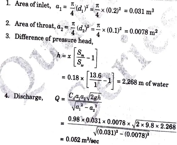
a. A horizontal venturimeter with inlet diameter 200 mm and throat diameter 100 mm is employed to measure the flow of water. The reading of the connected differential manometer is 180 mm of mercury. Calculate the rate of flow if the coefficient of discharge is 0.98.
Ans. Given: d1 = 200 mm = 0.2 m, d2 = 100 mm = 0.1 m, x = 180 mm
=0.18 m, Cd = 0.98
To Find : The rate of flow, Q.
Data Assumed: For mercury Sm = 13,6 and for water, Sw = 1.
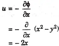
b. For a two-dimensional flow the velocity potential function is given by the expression
i. Determine velocity components in x and y directions.
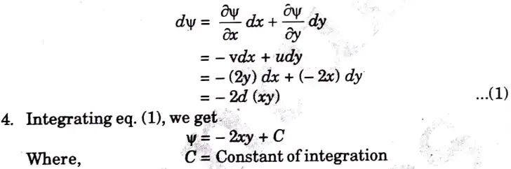
ii. Determine stream function.
Ans. Given : ɸ = x2 – y2
1. The velocity components in x direction,
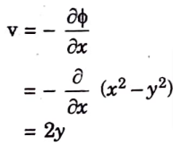
2. The velocity components in y direction,
3. The differential dΨ for the stream function,
c. Derive the expression for energy thickness.
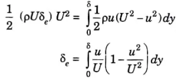
Ans. 1. It is defined as the distance, measured perpendicular to the boundary of the solid body, by which the boundary should be displaced to compensate for the reduction in kinetic energy of the flowing fluid on account of boundary layer formation. It is denoted by δe or δ**
2. Mass of flow per second through elementary strip = pudy
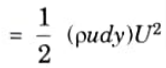
3. KE of this fluid inside the boundary layer
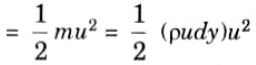
4. KE of same mass of fluid before entering the boundary layer
5. Loss of KE through elementary strip
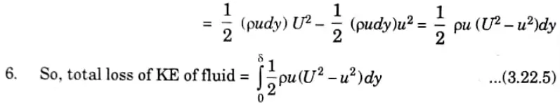
7. Let 5, be the distance by which plate is displaced to compensate for reduction in KE. Then, loss of KE through δe of fluid flowing with velocity U
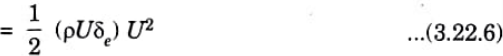
8. On equating eq. (3.22.5) and (3.22.6), we have
d. Explain the governing of the Pelton turbine with a neat sketch.
Ans. Governing Mechanism of Pelton Turbine
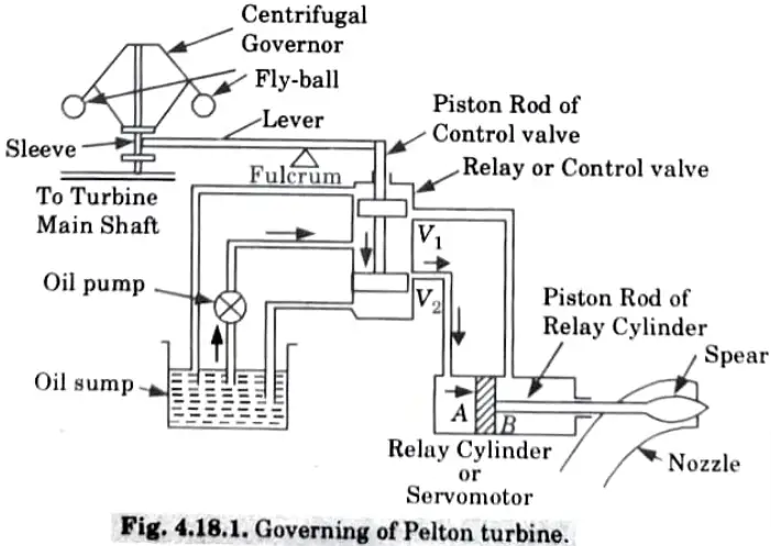
i. When the Load on Generator Decreases:
1. When the load on the generator decreases, the speed of generator and hence the turbine increases beyond normal speed.
2. The fly-balls of the centrifugal governor move outward due to the increased centrifugal force on them.
3. Due to the outward movement of the fly-balls, the sleeve moves up. As a consequence the portion of the lever to the right of the fulerum moves down pushing the piston rod of the control valve downwards.
4. This closes the valve V1 and opens the valve V2.
5. A gear pump pumps oil from the oil sump to the relay valve or control valve. Oil flows through valve V and exerts force on the face A of the piston of the relay cylinder.
6. The piston rod along with the spear moves to the right. This decreases the area of flow of the nozzle and hence, the rate of water flows to the turbine.
7. Consequently the speed of the turbine decreases till it becomes normal.
ii. When the Load on Generator Increases:
1. When the load on the generator increases, the speed of generator and hence the turbine decreases beyond normal speed.
2. The fly-balls of the centrifugal governor move inward due to the decreased centrifugal force on them.
3. Due to the inward movement of the fly-balls, the sleeve moves down and the piston rod of control valve goes up.
4. This closes the valve V2 and opens the valve V1.
5. Oil flows through valve V1 and exerts force on the face B of the piston of the relay cylinder.
6. The piston rod along with the spear moves to the left. This increases the area of flow of the nozzle and hence, the rate of water flows to the turbine.
7. As a consequence, the speed of the turbine increases till it becomes normal.
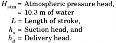
e. Explain the ideal indicator diagram. Describe the effect of friction in suction and delivery pipes on indicator diagrams.
Ans. A. Ideal Indicator Diagram : The graph between the pressure head and stroke length of the piston for one complete revolution of the crank under ideal conditions is known as ideal indicator diagram.
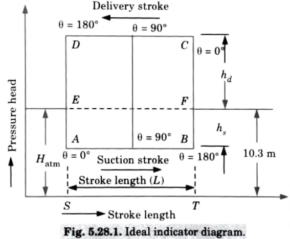
2. As shown in Fig. 5.28.1, different notations are taken as
3. During suction stroke, the pressure head in the cylinder is constant and equal to suction head (hs) which is below the atmospheric pressure head (Hatm) by a height of hs
4. This pressure head during suction stroke is represented by a horizontal line AB which is below the line EF by the height hs (suction head).
5. During the delivery stroke, pressure head in cylinder is constant and equal to delivery head (hd)this is represented by line CD. This line CD is above the line EF atmospheric pressure) by a height of hd.
Section C : Long Question
3. Attempt any one part of the following
a. Discuss the effect of increase in temperature on viscosity of fluids along with the logic.
Ans: 1. The viscosity of gases increases as temperature rises, but the viscosity of liquids decreases.
2. This is because cohesive forces and the transfer of molecular momentum are what cause the viscous forces in a fluid.
3. Because of how tightly packed molecules are in liquids, cohesive forces predominate over molecular momentum transmission. As temperature rises, the cohesive forces weaken, which causes the viscosity to drop.
4. However, the cohesive force is weak in the case of gases, and molecular momentum transmission predominates.
5. As temperature rises, molecular momentum transfer increases and viscosity follows.
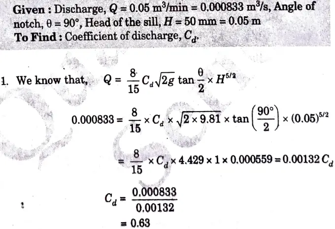
b. Illustrate the difference between notch and weir. During an experiment in a laboratory 0.05 m3 of water flowing over a right-angled notch was collected in 1 minute. If the head of the sill is 50 mm, calculate the coefficient of discharge.
Ans. A. Difference between Notch and Weir :
| S. No. | Notch | Weir |
| 1. | The size of notch is very small. | The size of weir is large. |
| 2. | It is used to determine the flow through small tanks or pipes. | It is used to measure the flow of rivers. |
B. Numerical:
4. Attempt any one part of the following
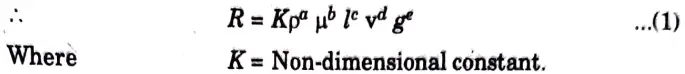
a. The resistance R experienced by a partially submerged body depends upon the velocity v, length of the body l, viscosity of the fluid µ, density of the fluid p and gravitational acceleration g. Using Buckingham’s pi theorem, determine an expression for R.
Ans. 1. The resistance R depends on density p, viscosity 4, length l, velocity v, acceleration g.
2. Substituting the dimensions on both sides of the eq. (1), we get
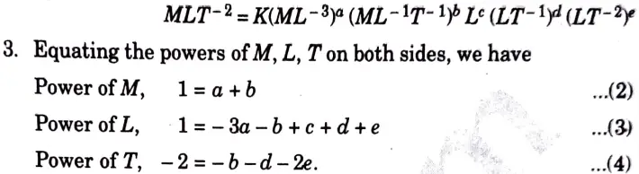
There are five unknowns and equations are only three. Expressing the three unknowns in terms of two unknowns (µ and g). Hence expressing a, c and d in terms of b and e and solving, we get
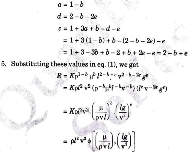
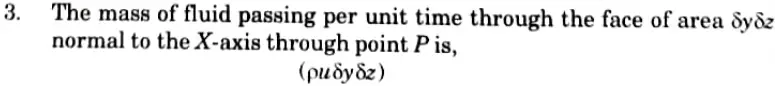
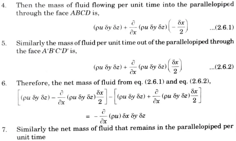
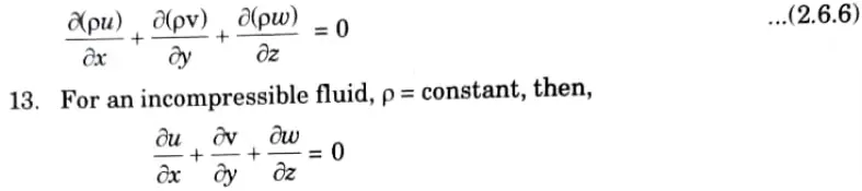
b. Illustrate the derivation for the continuity equation for three dimensional flow.
Ans.
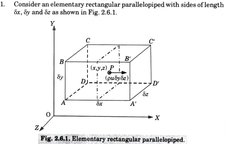
2. Let the centre of the parallelopiped be at a point Pl, y, 2) where the velocity components in the x,y and z directions are u, v and w respectively and p be the mass density of the fluid.
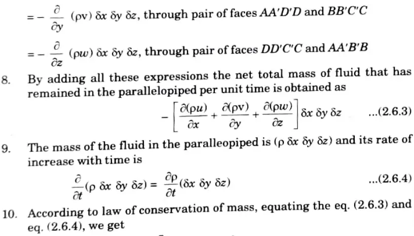
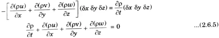
11. Eq. (2.6.5) represents the continuity equation in cartesian coordinates in its most general form which is applicable for steady as well as unsteady flow, uniform and non-uniform flow, and compressible as well as incompressible fluids.

5 Attempt any one part of the following.
a. Illustrate :
i. Siphon
Ans. 1. Syphon is a long bent pipe employed for carrying water from a reservoir at a higher elevation to another reservoir to a lower elevation when the two reservoirs are separated by a hill or high level ground in between as shown in Fig.
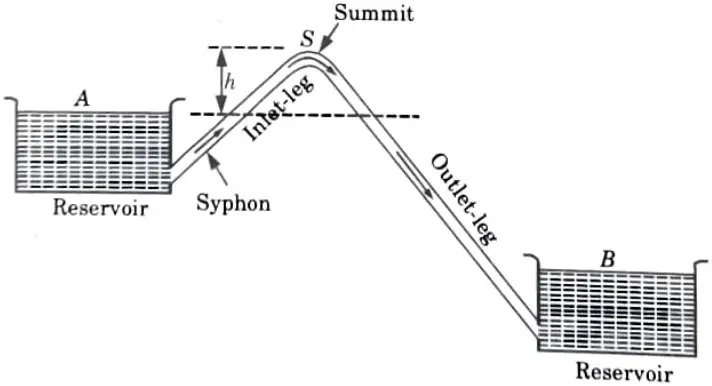
2. The highest point (S) of the syphon is called the summit.
3. The pressure at the point S is less than atmospheric pressure (Since S lies above the free water surface in the tank A).
4. When the pressure at S becomes less than 2.7 m of water absolute, the dissolved air and other gases would come out from water and collect at the summit. Therefore syphon should be so laid that no section of the pipe will be more than 7.6m above the hydraulic gradient at the section.
5. Moreover, in order to limit the reduction of the pressure at the summit the length of the inlet-leg (rising portion of the syphon) of the syphon is also required to be limited.
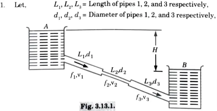
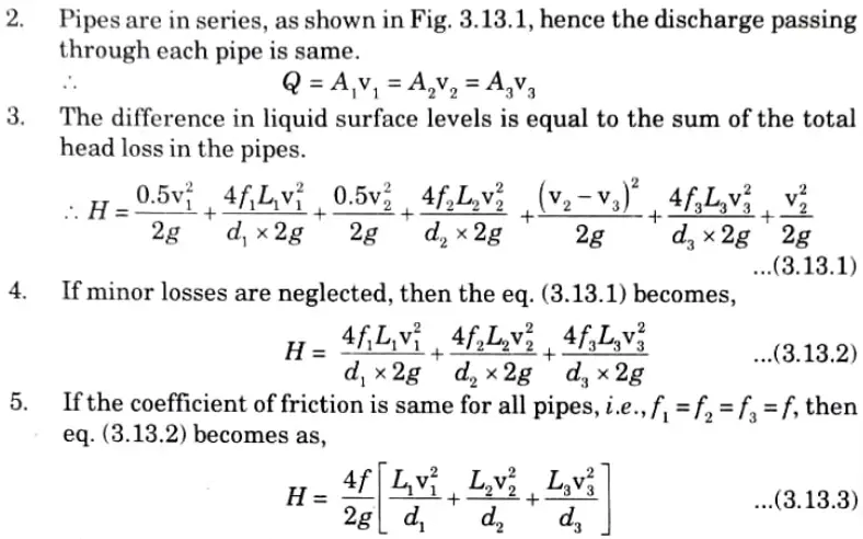
ii. Pipes in series.
Ans.
iii. Total energy line
Ans:
1. The energy gradient line is another name for the total energy line (TEL) (EGL).
2. It is well known that the potential head, pressure head, and velocity head are the sum of the total head with respect to any arbitrary datum.
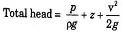
3. As the fluid moves through the pipe, head (or energy) is lost, and the overall amount of energy decreases in the direction of flow.
4. The resultant line is referred to as the total line if the total energy at various points along the pipe’s axis is plotted and connected by it (TEL).
b. A kite 0.8 m x 0.8 m weighing 3.924 N assumes an angle of 12°· to the horizontal. The string attached to the kite makes an angle of 45° to the horizontal. The pull on the string is 24.525 N when the wind is flowing at a speed of 30 km/hour. Calculate the corresponding coefficient of drag and coefficient of lift. Density of air is given as 1.25 kg/m3
Ans.
6. Attempt any one part of the following:
a. Illustrate the derivation for the expressions of :
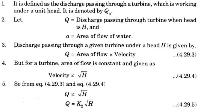
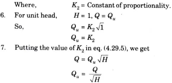
i. Unit discharge for a turbine.
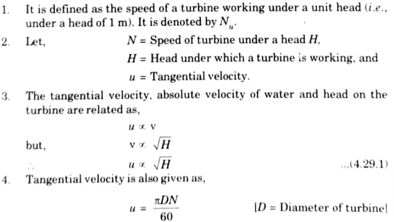
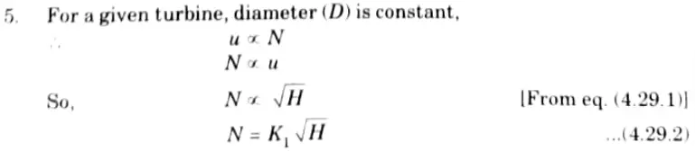
ii. Unit speed for a turbine.
Ans. ii. Unit speed for a turbine:

i. Unit discharge for a turbine:
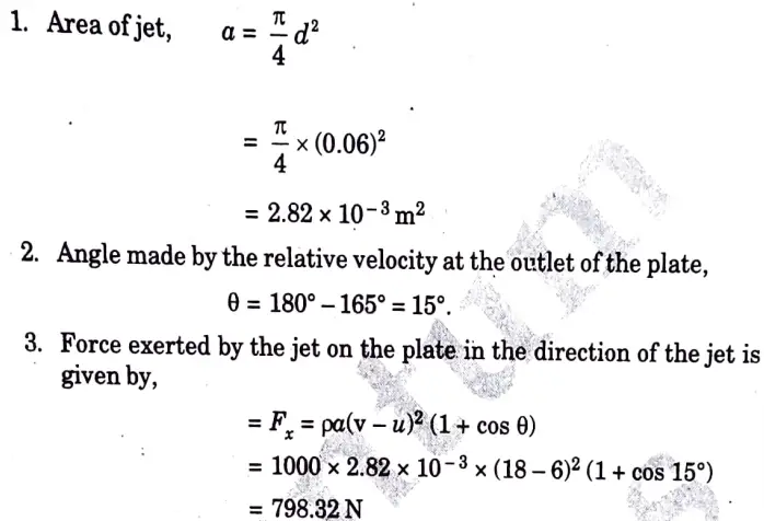
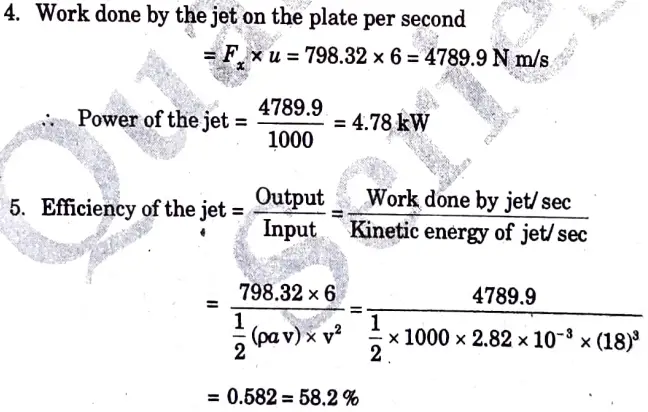
b. A jet of water; 60 mm in diameter, strikes a curved plate at its center with a velocity of 18 mis. The curved vane is moving with a velocity of 6 m is in the direction of the jet. The jet is deflected through an angle of 165°. Assuming the plate to be smooth, calculate :
i. Thrust on the plate in the direction of the jet.
ii. Power of the jet.
iii. Efficiency “of the jet.
Ans. Given: Diameter of the jet,d = 60 mm =0.06 m,
Velocity of the jet, v = 18 m/s,
Velocity of the plate, u=6 m/s, Angle of deflection of the jet = 165
7. Attempt any one part of the following :
a. Illustrate the derivation for the :
i. Specific speed of centrifugal pump.
Ans. A. Specific Speed:
1. It is defined as the speed of a geometrically similar pump which would deliver one cubic meter of liquid per second against a head of one meter.
2. It is denoted by Ns.
B. Expression for Specific Speed:
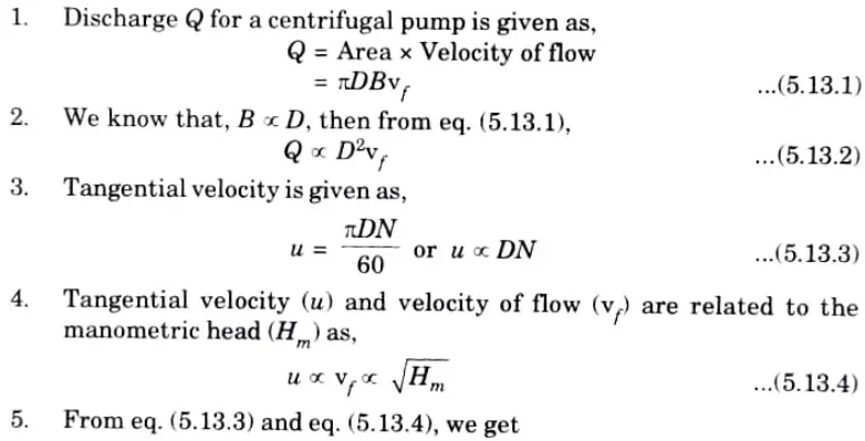
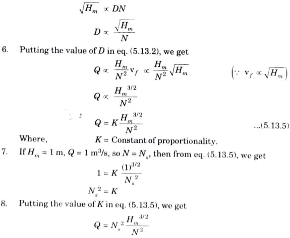
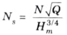
This expression is showing the specific speed of pump.
ii. Minimum speed for starting a centrifugal pump.
Ans.
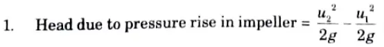
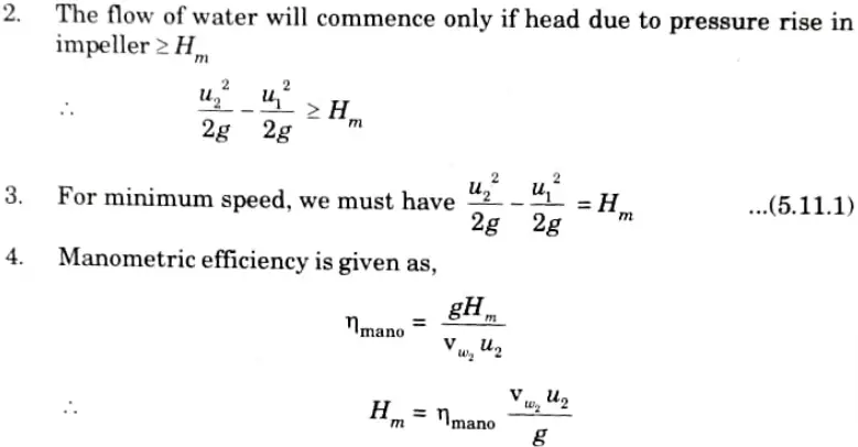
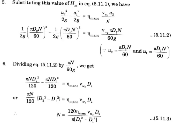
Eq. (5.11.3) gives the minimum starting speed of the centrifugal pump.
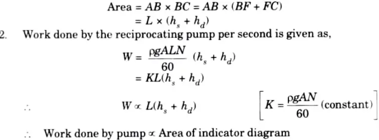
b. Illustrate the classification of reciprocating pumps. Show that the work done by a reciprocating pump is proportional to the area of the indicator diagram.
Ans. A Classification of Reciprocating Pump :
a. According to the Water being in Contact with Piston:
1. Single acting pump.
2. Double acting pump.
b. According to Number of Cylinders Provided:
1. Single cylinder pump.
2. Double cylinder pump.
3. Triple cylinder pump.
B. Proof:
1. From the indicator diagram (Refer Fig. 5.28.1), area of diagram is given as,

Fluid Mechanics & Fluid Machines Quantum, Syllabus, Important Questions
| Label | Link |
|---|---|
| Subject Syllabus | Syllabus |
| Short Questions | Short-question |
| Important Unit-1 | Unit-1 |
| Important Unit-2 | Unit-2 |
| Important Unit-3 | Unit-3 |
| Important Unit-4 | Unit-4 |
| Important Unit-5 | Unit-5 |
| Question paper – 2021-22 | 2021-22 |
Fluid Mechanics & Fluid Machines Quantum PDF: | AKTU Quantum PDF:
| Quantum Series | Links |
| Quantum -2022-23 | 2022-23 |
AKTU Important Links | Btech Syllabus
| Link Name | Links |
|---|---|
| Btech AKTU Circulars | Links |
| Btech AKTU Syllabus | Links |
| Btech AKTU Student Dashboard | Student Dashboard |
| AKTU RESULT (One VIew) | Student Result |
1 thought on “Question Paper 2022-23- Fluid Mechanics & Fluid Machines AKTU | Important Questions”