
Providing Unit-04 Impact of Jet, Impulse Turbine and Reaction Turbines | Important Question in Fluid Mechanics & Fluid Machines AKTU. Hope this blog will help you in your upcoming exams.
Dudes 🤔.. You want more useful details regarding this subject. Please keep in mind this as well.

Important Questions For Fluid Mechanics & Fluid Machines :
*Unit-01     *Unit-02
*Unit-03    *Unit-04
*Unit-05    *Short-Q/Ans
*Question-Paper with solution 21-22
Q1. Derive the formula for dynamic force exerted by fluid jet on stationary plate for the following cases:
- i. When the plate is normal to jet.
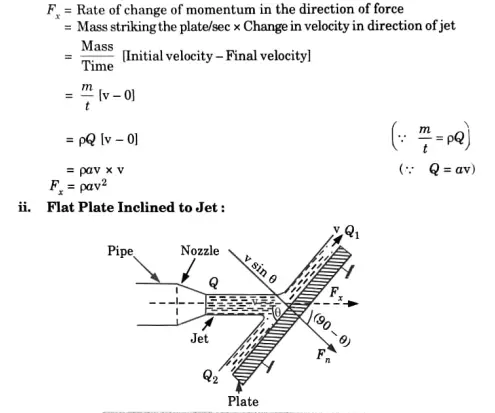
- ii. Flat plate inclined to jet.
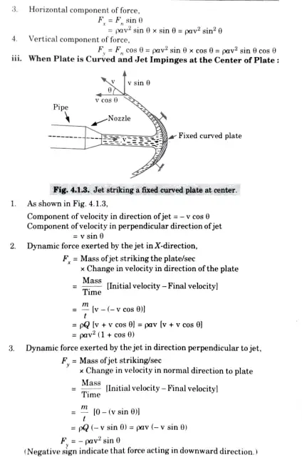
- iii. When the plate is curved and the jet impinges at the center of the plate.
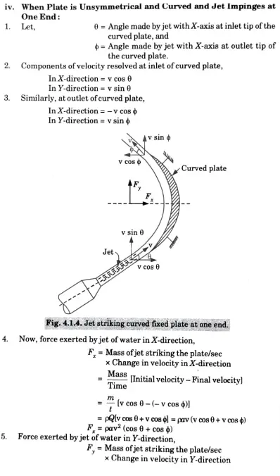
- iv. When the plate is unsymmetrical and curved and jet impinges at one end.
Answer
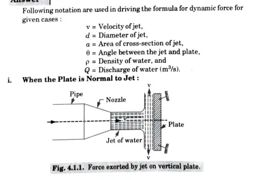
- Consider ajet of water coming out from the nozzle, striking a lat vertical
plate as shown in Fig. 4.1.1. - Plate is at 90° to the jet and jet after striking will move along the plate. So, velocity component of water after strike, in direction of jet will be zero.
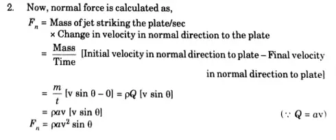
- Dynamic force exerted by the jet on the plate in direction of jet is calculated as,
- If plate is smooth and there is no loss of energy, then jet will move over
the plate with a velocity (v) as shown in Fig. 4.1.2.

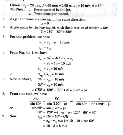
Q2. A jet of water of diameter 50 mm having a velocity of 20 m/s strikes a curved vane which is moving with a velocity of 10 m/s in the direction of the jet. The jet leaves the vane at an angle of 60 degree to the direction of motion of the vane at outlet. Determine.
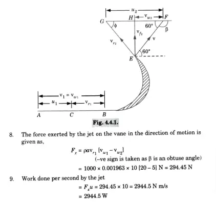
I. Force exerted by the jet on the vane in the direction of motion.
ii. Work done per second by the jet.
Q3. Discuss the classification of hydraulic turbines. OR Classify hydraulic turbines in detail.
Answer
Hydraulic turbines are classified as follows
a. According to the Type of Energy Available at Inlet :
i. Impulse Turbine: All of the water’s available energy is transformed into kinetic energy, also known as velocity head, in an impulse turbine.
Example: Pelton wheel turbine.
Reaction Turbine : Only a portion of the water’s available energy is transformed into kinetic energy at the entrance to the runner of a reaction turbine; the majority is still present as pressure energy.
Example: Prancis turbine, Kaplan turbine.
b. According to the Direction of Flow through Runner:
Tangential Flow Turbine: The water in this turbine flows perpendicular to the runner’s path of rotation.
Example: Pelton wheel turbine.
Radial Flow Turbine: The water in this turbine moves in a radial direction.
Example: Francis turbine.
ii. Axial Flow Turbine: In this turbine, water mostly and completely flows through the runner in a direction parallel to its axis of rotation.
Example: Kaplan turbine.
iv. Mixed Flow Turbine: In this turbine, the water enters the runner from the outside in a radial direction and exits from the centre in a direction perpendicular to the runner’s axis of rotation.
Example: Modern Francis turbine.
e. According to the Head at Inlet of Turbine:
High Head Turbine: These are the types of turbines that can operate at very high heads of more than 250 m.
Example: Pelton wheel turbine.
ii. Medium Head Turbine: These are the turbines, and they can operate with a head of 60 to 250 metres.
Example Francis turbine.
iii. Low Head Turbine: These are the turbines that can operate with a head of less than 60 metres.
Example: Kaplan turbine.
According to the Specific Speed of the Turbine:
Low Specific Speed Turbine: Low specific speed ranging less than 60.
Example: Pelton wheel turbine.
ii. Medium Specific Speed Turbine: Ranging between 60 to 300.
Example: Francis turbine.
iii. High Specific Speed Turbine: Ranging between 300 to 1000.
Example: Kaplan turbine.
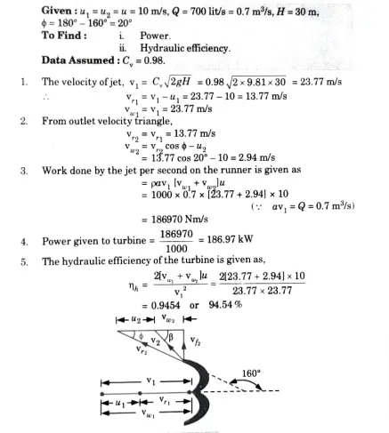
Q4. Pelton wheel has a mean bucket speed of 10 m/s with a jet of water flowing at a rate of 700 lits under a head of 30 m. The bucket deflects the jet through an angle of 160 degree. Calculate power and hydraulic efficiency.
Q5. Define specific speed of a turbine and derive an expression for the same. OR
Deduce an expression for the specific speed of a hydraulic turbine and explain how it is useful in practice.
A Specific Speed:
It is defined as the speed of a turbine which is identical in shape. geometrical dimensions, lade angles, gate openings, etc., with the actual turbine but of such a size that it will develop unit power when working under unit head. It is denoted by symbol Ns
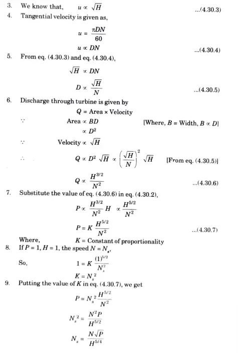
B. Derivation of the Specific Speed:
- Let, D = Diameter of actual turbine,
N= Specd of actual turbine,
u = Tangential velocity of turbine,
Ns = Specific speed of the turbine, and
V= Absolute velocity of water
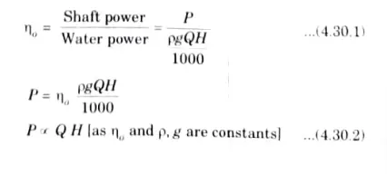
2.The overall efficiency of any turbine is given as
C. Usefulness or Significance of Specific Speed:
A particular speed is crucial while choosing the turbine. Knowing a turbine’s precise speed allows one to estimate how well it will work.
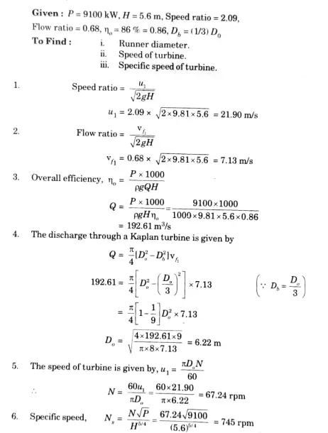
Que 6. A Kaplan turbine runner is to be designed to develop 9100 kW. The net available head is 5.6 m. If the speed ratio is 2.09, flow ratio = 0.68, overall efficiency = 86 % and the diameter of the boss is 1/3 the diameter of the runner. Find the diameter of the runner, its speed and the specific speed of the turbine.

Fluid Mechanics & Fluid Machines Quantum, Syllabus, Important Questions
| Label | Link |
|---|---|
| Subject Syllabus | Syllabus |
| Short Questions | Short-question |
| Important Unit-1 | Unit-1 |
| Important Unit-2 | Unit-2 |
| Important Unit-3 | Unit-3 |
| Important Unit-4 | Unit-4 |
| Important Unit-5 | Unit-5 |
| Question paper – 2021-22 | 2021-22 |
Fluid Mechanics & Fluid Machines Quantum PDF: | AKTU Quantum PDF:
| Quantum Series | Links |
| Quantum -2022-23 | 2022-23 |
AKTU Important Links | Btech Syllabus
| Link Name | Links |
|---|---|
| Btech AKTU Circulars | Links |
| Btech AKTU Syllabus | Links |
| Btech AKTU Student Dashboard | Student Dashboard |
| AKTU RESULT (One VIew) | Student Result |
4 thoughts on “Unit-04 Impact of Jet, Impulse Turbine and Reaction Turbines | Important Question in Fluid Mechanics & Fluid Machines AKTU”