In this Blog, We are discussing for Unit5-Centrifugal and Reciprocating Pumps | Fluid Mechanics & Fluid Machines AKTU | Important Questions . Hope this blog will help you in your upcoming exams.
Dudes 🤔.. You want more useful details regarding this subject. Please keep in mind this as well.

Important Questions For Fluid Mechanics & Fluid Machines :
*Unit-01     *Unit-02
*Unit-03    *Unit-04
*Unit-05    *Short-Q/Ans
*Question-Paper with solution 21-22
Q1. Give the constructional details of a centrifugal pump. Also explain its working.
Answer
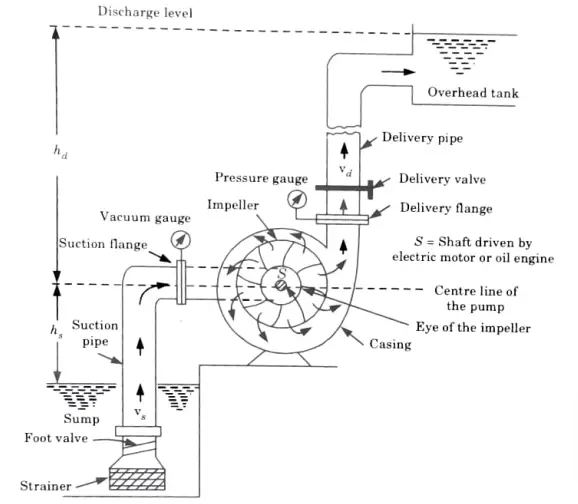
A Construction: Main parts of a centrifugal pump are:
a. Impeller:
1. A wheel (or rotor) having a row of backward-curving vanes is called an impeller (or blades).
2. It is attached to a shaft that connects to an electric motor.
3. The impellers are of following three types:
Shrouded or closed impeller.
ii. Semi-open impeller.
ii. Open impeller.
b. Casing:
1. The casing is an airtight chamber surrounding the pump impeller.
2. The following three types of casing are commonly employed
i. Volute Casing:
1. The area of flow gradually increases from the impeller outlet to the delivery pipe in this style of casing, lowering the flow velocity.
2. The volute casing experiences a rise in pressure as a result.
ii. Vortex Casing:
1. The casing is referred to as a vortex casing if a circular chamber is present between the impeller and the volute chamber.
2. Such a pump is referred to as a volute pump with vortex chamber, and the circular chamber is known as a vortex or whirlpool chamber.
3. The vortex chamber converts some of the kinetic energy into the pressure energy.
iii. Casing with Guide Blades:
1. The impeller is encircled by a series of guide blades (or vanes) positioned on a ring called as a diffuser in this type of casing.
2. While diffuser blade machines are most efficient, they perform less well when a variety of operating circumstances are necessary.
c. Suction Pipe:
Suction pipe is the line that runs from the sump from where liquid is to be drawn up to the center/eye of the impeller.
2. To stop solid particles, trash, etc. from entering
A strainer is attached to the bottom end of the suction pipe.
d. Delivery Pipe:
1. The delivery pipe is the pipe that carries liquid to the desired height and is attached at its lower end to the pump’s outlet.
2. To control the flow of water, a delivery valve is included on the delivery pipe.
B. Working of Centrifugal Pump:
- The first step in the operation of a centrifugal pump is priming.
- Priming is the process of entirely filling the delivery pipe up to the delivery valve, the pump’s casing, and the suction pipe with the liquid that will be pumped, leaving no room for air.
- The delivery valve is kept closed after the pump has been primed while the electric motor is turned on to rotate the impeller.
- The forced vortex created by the impeller’s rotation in the liquid-filled case gives the liquid a centrifugal head, which raises the pressure throughout the liquid mass.
- Now, the impeller just stirs the liquid inside the casing while the delivery valve is closed.
- When the delivery valve is opened, the liquid is forced to flow outward and radially, exiting the impeller’s outer vanes with a high velocity and pressure.
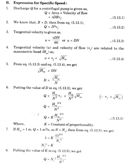
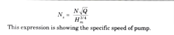
Q2. Define specific speed of a centrifugal pump and derive the equation for the same.
A Specific Speed:
1. It is defined as the speed of a geometrically similar pump which would
deliver one cubic meter of liquid per second against a head of one meter.
2.It is denoted by Ns
Q3 What is priming in a centrifugal pump ? Why is it done? What is a self-priming pump ? Explain.
Answer
A. Priming and its Necessity:
- In order to eliminate air, gas, or vapour from these components, the suction pipe, pump casing, and a piece of the delivery pipe are entirely filled with water by an external source before the pump is started.
- The head created by the pump is defined as the work performed by an impeller per unit weight of liquid per second. This indicates that the head produced by a pump when it is operating in air is measured in terms of metres of air.
- The head will produce in terms of metres of water if the pump is primed with water.
- However, because air has a low density, the heat produced by the pump is likewise minimal, possibly even negligible, and water may not be drawn in by the pump as a result.
- To avoid this difficulty priming of the centrifugal pump is necessary.
B. Self-priming Pump:
- The internal construction of some pumps is such that special arrangements containing a supply of liquid are provided in the suction pipe due to which automatic priming of the pump occurs, such pumps are known as ‘self-priming pumps.
- Self-priming pumps are designed with a large reservoir surrounding the pump casing.
- The advantage associated with self-priming pump is being portable in nature.
- These are commonly used in sewage lit stations, where raw sewage is pumped into a treatment facility.
Q4. With the help of a neat sketch explain the construction and working principle of reciprocating pump. OR With the help of a neat sketch explain the working principle of reciprocating pump.
A Construction of Reciprocating Pump:
1. As shown in Fig. 5.21.1, a reciprocating pump consists of a piston or plunger inside a cylinder.
2. The piston rod and connecting rod link the piston to the crankshaft. Electric motors are used to turn the crankshaft.
3. Non-return suction and delivery valves are used to join the suction and delivery pipes to the cylinder.
4. Non-return valves are one-way valves that permit just one direction of liquid flow.
5. In this instance, the delivery valve permits liquid to pass from the cylinder to the delivery pipe while the suction valve permits liquid to pass from the suction pipe to the cylinder.
B. Working of Reciprocating Pump:
1. According to Fig. 5.21.1, a reciprocating pump consists of a piston or plunger moving back and forth inside a cylinder.
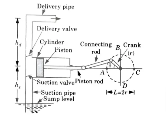
2. The piston in the cylinder travels to the right as the crank moves outward (from A to C), creating a vacuum in the cylinder.
3. Liquid is sucked into the cylinder through the non-return suction valve as a result of the pressure differential between the sump and the cylinder.
4. The delivery valve stays closed throughout this outward stroke.
5. The piston advances to the left during the crank’s return stroke (from C to A), increasing the pressure inside the cylinder, which opens the delivery valve and closes the inlet valve.
The liquid is forced into the delivery pipe and is raised to a required height.
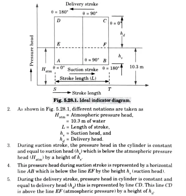
Q5. What do you understand by an indicator diagram ?Explain the ideal indicator diagram.
Answer
A Indicator Diagram:
1. It is described as the line drawn between the pressure head in the cylinder and the piston’s distance from inner dead centre during a whole crankshaft revolution.
2. In a reciprocating pump, a piston’s stroke length determines how far it may travel. A graph between the pressure head and stroke length is an indicator graphic.
3. Stroke length and pressure head are treated as standard and abscissa, respectively.
B. Ideal Indicator Diagram:
1. The ideal indication diagram is the line drawn between the pressure head and the piston’s stroke length for a crankshaft rotation under ideal circumstances.
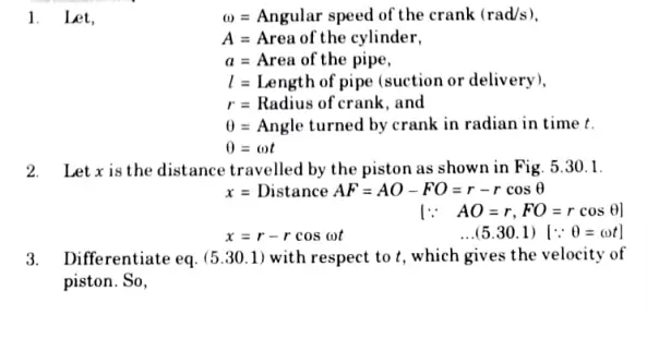
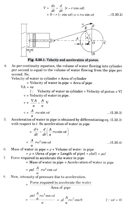
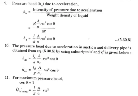
Q6. Derive an expression for accelerating head in reciprocating pump assuming piston motion by SHM.

Fluid Mechanics & Fluid Machines Quantum, Syllabus, Important Questions
| Label | Link |
|---|---|
| Subject Syllabus | Syllabus |
| Short Questions | Short-question |
| Important Unit-1 | Unit-1 |
| Important Unit-2 | Unit-2 |
| Important Unit-3 | Unit-3 |
| Important Unit-4 | Unit-4 |
| Important Unit-5 | Unit-5 |
| Question paper – 2021-22 | 2021-22 |
Fluid Mechanics & Fluid Machines Quantum PDF: | AKTU Quantum PDF:
| Quantum Series | Links |
| Quantum -2022-23 | 2022-23 |
AKTU Important Links | Btech Syllabus
| Link Name | Links |
|---|---|
| Btech AKTU Circulars | Links |
| Btech AKTU Syllabus | Links |
| Btech AKTU Student Dashboard | Student Dashboard |
| AKTU RESULT (One VIew) | Student Result |
2 thoughts on “Unit5-Centrifugal and Reciprocating Pumps | Fluid Mechanics & Fluid Machines AKTU | Important Questions”