Find out more about B.Tech AKTU Quantum Book Short Question Notes on Microwave and Radar Engineering. Dive into electromagnetic wave fundamentals, radar systems, and modern communication technologies.
Dudes 🤔.. You want more useful details regarding this subject. Please keep in mind this as well.

Important Questions For Microwave and Radar Engineering:
*Quantum                *B.tech-Syllabus
*Circulars                 *B.tech AKTU RESULT
* Btech 4th Year     * Aktu Solved Question Paper
Unit-I: Transmission Line and Waveguide (Short Question)
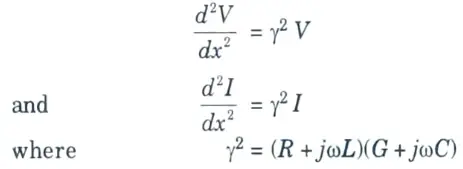
Q1. Write the transmission line equations in differential form.
Ans. The transmission line equations are
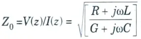
Q2. Define characteristic impedance.
Ans. When the reflected wave in the line is zero, the ratio V(z)/I(z) is called the characteristic impedance of the line and is defined by
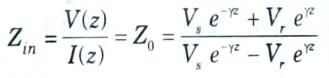
Q3. What do you mean by input impedance of line ?
Ans. The impedance of the line at z looking towards the load is called input impedance of the line.
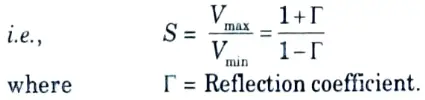
Q4. Define VSWR.
Ans. The VSWR stands for Voltage Standing Wave Ratio. It is defined as the ratio of maximum to minimum voltage.
Q5. Compare microstrip line with strip lines.
Ans.
| S. No. | Microstrip line | Strip line |
| 1. | Mode of propagation is Quasi-TEM. | Mode of propagation is nearly TEM. |
| 2. | Due to its open structure it radiates electromagnetic energy. | The energy is confined inside the line cross-section. |
| 3. | Microstrip lines are suitable for mounting active components. | Strip lines are not suitable for mounting active components. |
Q6. What are the advantages of microstrip line ?
Ans. i. Fabrication cost is low.
ii. Better inter-connection features and easier fabrication.
iii. Provides one free and accessible surface on which solid state devices can be placed.
Q7. Give the limitations of microstrip line.
Ans. i. Because of the openness of the microstrip structure, they suffer from increased radiation losses or interference from neighbouring conductors.
ii. The proximity of the air-dielectric air interface with the microstrip conductor at the interface causes an electric and magnetic field discontinuity. This complicates analysis.
Q8. Define waveguide.
Ans. A waveguide is a hollow metallic tube with a uniform cross section for transmitting electromagnetic waves by successive reflections from the tube’s inner walls.
Q9. Name the various parameters associated with the waveguides.
Ans.
- i. Velocity of propagation.
- ii. Cut-off wavelength.
- iii. Cut-off frequency.
- iv. Guide wavelength.
- v. Group velocity.
- vi. Characteristic impedance.
Q10. Compare TE and TM modes.
Ans.
| S. No. | TE mode | TM mode |
| 1. | It is transverse electric mode. | It is transverse magnetic mode. |
| 2. | EZ = 0 i.e., energy transmission is done by HZ. | HZ = 0 i.e., energy transmission is done by EZ. |
| 3. | Dominant mode is TE10 mode. | Dominant mode is TM10 mode. |
| 4. | TE01 and TE10 mode exists. | TM01 and TM10 modes do not exist. |
Q11. Why TEM mode cannot exist in rectangular waveguide ?
Ans. TEM mode is characterised by electric fields (Ez) and magnetic fields (Hz) perpendicular to one another and perpendicular to the direction of propagation. But for rectangular waveguide Ez = 0 and Hz = 0, hence TEM wave cannot exist inside a rectangular waveguide.
Q12. What is evanescence mode in waveguides ?
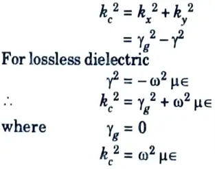
Ans. There will be no wave propagation in the waveguide if ω2cμε = k2c and γg = 0. This is the evanescence mode in waveguides.
Q13. Define cut-off wave number (kc). Show that k2c = ω2με for lossless dielectric.
Ans. kc is define as the reciprocal of the cut-off wavelength and also can be written as,
Q14. Differentiate dominant and degenerative mode in waveguide.
Ans.
| S. No. | Dominant mode | Degenerative mode |
| 1. | In a waveguide having multiple propagation modes, the mode with the lowest cut-off frequency is referred to as the dominant mode. | When two or more modes in a waveguide have the same cut-off frequency, they are considered to be degenerate modes. |
| 2. | For rectangular TE10 is the dominant mode. | For rectangular waveguide TEmm or TMmn modes for which both m = 0, n ≠ 0 will always be degenerate modes. |
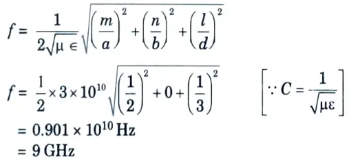
Q15. Calculate the lowest resonant frequency of a rectangular resonator of dimensions a = 2 cm, b = 1 cm, d = 3 cm.
Ans. Given: a = 2 cm, b = 1 cm, d = 3 cm
To Find: Lowest resonant frequency.
For lowest resonant frequency,
m = 1
n = 0
l = 1, i.e., dominant mode
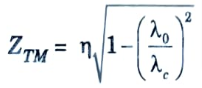
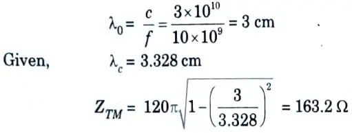
Q16. A rectangular waveguide with cut-off wavelength 3.328 cm operates in TM11 mode at 10 GHz. Determine the characteristic wave impedance.
Ans. Given: λc = 3.328 m, f = 10 GHz.
To Find: Characteristic wave impedance
Characteristic wave impedance,
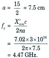
Q11. For circular waveguide having an internal diameter of 15 cm, calculate the cut-off frequency for TM12 mode when the roots of Bessel function is 7.02.
Ans. Given: d = 15 cm, X’nm = 7.02
To Find: fc.
Unit-II: Passive Microwave Devices (Short Question)
Q1. Define microwave junction.
Ans. The point of interconnection of two or more microwave devices is called microwave junction.
Q2. What do you mean by microwave coupler ?
Ans. Microwave couplers are devices that shift a portion of a signal from one transmission line to another.
Q3. What are the parameters to determine the performance of directional coupler?
Ans.
- i. Directivity.
- ii. Coupling factor.
- iii. Insertion loss.
- iv. Passive Microwave Devices
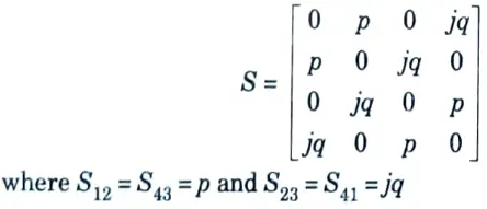
Q4. Give the S-matrix of a directional coupler
Ans.
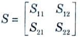
Q5. Define S-Matrix.
Ans. Travelling waves with associated powers can be specified by S-Parameters or Scattering Parameters, which are represented in a matrix form, called the Scattering Matrix or S-Matrix, when they scatter out via the ports, the microwave junction.
Q6. Why the S-parameter but not the H, Y and Z-parameters are used in microwaves ?
Ans. i. A lack of terminal voltage and current metering equipment.
ii. Short and open circuits are difficult to achieve at broadband frequencies.
iii. The strapping method increases the frequency separation between the p-mode and the higher neighbouring mode.
Q7. List some properties of S-parameters.
Ans. i. Scattering matrix [S] is always a square matrix.
ii. [S] is symmetric matrix i.e., [Sij = Sji].
iii. [S] is unitary matrix for lossless junction i.e., [S] [S*] = [I].
iv. Zero diagonal elements for perfect matched network.
Q8. What is E-plane tee ?
Ans. An E-plane tee is a waveguide tee with the axis of its side arm parallel to the main guide’s electric field (E).
Q9. Write any two properties of E-plane tee microwave device.
Ans. 1. In E-plane tee awave incident at port 3 will result in a wave at ports 1 and 2, which are equal in magnitude but opposite in phase,
i.e., S31 = S13 = -S23 = -S32, S12 = S21
2. All diagonal elements of the S-matrix of E-plane tee junction cannot be zero simultaneously since the tee junction cannot be matched to all the tee arms simultaneously.
Q10. What is H-plane tee ? What is other name used for H-plane tee?
Ans. An H-plane tee is a waveguide with its side arm’s axis shunting the E-field or parallel to the main guide’s H-field. This is also known as a shunt tee.
Q11. What is magic tee and where it is used ?
Ans. A magic tee is a hybrid of the E-plane and H-plane tees. It is also referred to as a hybrid tee. It is often used for mixing, duplexing, and measuring impedance.
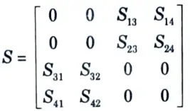
Q12. Give the S-matrix of a magic tee.
Ans.
Q13. Define rat race circuits.
Ans. An annular line of proper electric length (i.e., to sustain standing waves) is joined to four arms at proper intervals by series or parallel junctions to form a hybrid ring. A rat race circuit is another name for a hybrid ring.
Q14. Give the difference between isolator and circulator.
Ans.
| S. No. | Isolator | Circulator |
| 1. | It is two port device. | It has multiple port typically 3 or 4. |
| 2. | Isolators are used in optical amplifier and laser to prevent reflections. | Circulators are used to construct optical add/drop multiplexer. |
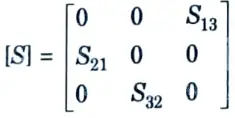
Q15. Write the S-parsmeter matrix of a 3 port circulator shown in Fig.

Ans. For a perfectly matched, lossless, non-reciprocal 3 port circulator, the S-matrix is
Unit-III: Microwave Tubes (Short Question)
Q1. What are the limitations of conventional active devices at microwave frequency ?
Ans. i. Inter-electrode capacitance effect.
ii. Lead inductance effect.
iii. Transit time effect.
iv. Gain bandwidth limitation.
Q2. How the limitations of conventional tubes at microwave frequency can be overcome?
Ans. i. Re-entrant cavities.
ii. Slow wave tubes.
Q3. What do you mean by two cavity klystron ?
Ans. Two cavities The klystron is a popular microwave amplifier that works on the idea of velocity and current modulation. It is made up of an input cavity called the buncher cavity and an output cavity called the catcher cavity.
Q4. List some applications of two cavity klystron amplifier.
Ans. i. Global positioning system (GPS).
ii. RADAR transmitters.
iii. Used as power oscillator.
Q5. What is a reflex klystron ?
Ans. The reflex klystron oscillator is a single cavity klystron that overcomes the drawbacks of the two cavity klystron oscillator. It is a low-power generator with a frequency range of 1 to 25 GHz and an output power of 10 to 500 mW.
Q6. What are the applications of reflex klystron ?
Ans. 1. In radar transmitting and receiving set.
2. Communication links.
3. Signal source in microwave generators.
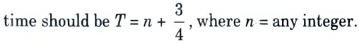
Q7. What is the condition for sustained oscillation in reflex klystron ?
Ans. To maintain oscillations, the time it takes electrons to traverse into the repeller space and back to the gap (known as transit time) must be optimised. In general the optimum transit
Q8. Give the drawbacks of klystron amplifiers.
Ans. 1. The Klystron amplifier does not have a low noise device. As a result, it is typically employed in the transmitter rather than the receiver.
2. Because of the usage of resonant cavities, it has a narrow band.
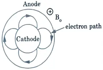
Q9. Draw and explain the trajectory of electron moving from cathode to anode if Hull magnetic field is applied in magnetron.
Ans. This means that if Bo > Boc the electron will not reach the anode.
Q10. What is strapping in magnetron ?
Ans. 1. Strapping refers to connecting alternate anode plates with two heavy gauge conducting rings that touch the anode poles at the dots. This is done in order to connect the 2𝛑 anode poles.
2. Strapping aids in establishing the magnetron’s dominant mode (here 𝛑-mode).
Q11. Define the purpose of slow wave structures used in TWT amplifiers.
Ans. Slow wave structures are intended to generate high gain over a wide bandwidth. Slow wave structures are unique circuits used in microwave tubes to slow wave velocity in a certain direction, allowing the electron beam and signal wave to interact.
Q12. Give two applications of TWT.
Ans. i. As a low noise RF amplifier in broadband microwave receivers.
ii. Due to long tube life, TWT is used as power output tube in communication satellites.
Q13. State the differences between TWT and klystron.
Ans.
| S. No. | TWT | Reflex klystron |
| 1. | Traveling wave tubes (TWT) are broadband devices. | Reflex klystrons are essentially narrowband devices. |
| 2. | Both the electron beam and the RF field are moving in the same direction at almost the same velocity. | The electron beam travels and the RF field remains stationary. |
Q14. What is backward wave oscillator (BWO) ? State the application of BW0.
Ans. A. BWO: A microwave continuous wave (CW) oscillator with outstanding tuning capabilities and frequency coverage range is known as a backward wave oscillator (BWO).
B. Applications:
- i. Signal sources in instruments and transmitters.
- ii. As a broadband noise source.
- iii. As a noiseless oscillator with bandwidth in the frequency range 3 to 9 GHz.
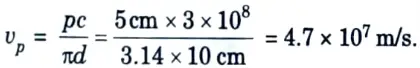
Q15. In a helical slow wave structure if pitch is 5 cm and diameter is 10 cm, calculate the axial velocity with which wave will propagate.
Ans. Given: p = 5 cm, d = 10 cm
To Find: Axial velocity.
Unit-IV: Microwave Measurements (Short Question)
Q1. Give any two features of microwave measurement.
Ans. Two features of microwave measurements are as follows:
- i. Unlike low frequency measurements, many characteristics measured at microwave frequencies are relative and do not require absolute values to be known.
- ii. For power measurement, knowing the ratio of two powers rather than the specific input or output powers is usually adequate.
Q2. Define insertion loss.
Ans. The difference in power arriving at the terminating load with and without the network in the circuit is termed as insertion loss.
Q3. Why the low frequency parameters cannot be measured in microwaves ?
Ans. 1. It is easier to measure voltage and current at low frequencies and use them to determine power.
2. However, at microwave frequencies, they are difficult to measure and, because they fluctuate with transmission line position, are of little use in estimating power.
3. As a result, at microwave frequencies, measuring power directly is more desirable and simpler.
Q4. Give the names of two methods for measurement of frequency.
Ans. i. Using frequency counter.
ii. Beat frequency measurement method.
Q5. Define noise factor.
Ans. The noise factor is defined as the ratio of the device’s actual output noise power to the noise power available if the device were perfect (not contributing any noise).
Q6. What are the three main scales on VSWR meter ?
Ans. Three main scales on VSWR meter are as follows:
- i. The normal SWR scale can be used when VSWR is between 1 and 4.
- ii. The bottom of normal SWR scale can be used when the VSWR is between 3 and 10.
- iii. Expanded SWR scale can be used when the VSWR is less than 1.3.
Q7. What is bolometer ? Also give its types.
Ans. A bolometer is a temperature-sensitive device having resistance that fluctuates with temperature. This resistance change is proportional to the microwave power input.
There are two types of bolometer device:
- i. Barretter
- ii. Thermistor
Q8. Define barretter.
Ans. These are the devices with a positive temperature coefficient, and their resistance increases as the temperature rises.
Q9. What do you mean by thermistor ?
Ans. These are devices with a negative temperature coefficient of resistance, meaning their resistance lowers as the temperature rises.
Q10. What is the principle of calorimetric method of power measurement ?
Ans. The calorimetric method for measuring high power includes converting microwave energy into heat, absorbing this heat in a fluid (water), and then measuring the fluid’s temperature rise.
Q11. What do you mean by slotted line ?
Ans. One of the fundamental tools used in radio frequency testing and measurement at microwave frequencies is the slotted line.
Q12. Give one advantage of slotted line waveguide measurement for measurement of impedance over reflectometer method.
Ans. A reflectometer measures only the magnitude of impedance and not the phase angle, but a slotted line waveguide measurement measures both.
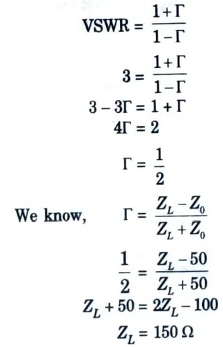
Q13. A 50 Ω loss line is terminated in unknown impedance. What is the load impedance if VSWR is 3 ?
Ans. Given: VSWR = 3, Z0 = 50 Ω
To Find: Unknown impedance (ZL)
Unit-V: Introduction to Radar System (Short Question)
Q1. What is radar ?
Ans. Radar is an electromagnetic technology used to detect and locate objects that reflect light, such as aircraft, ships, spacecrafts, cars, humans, and the natural environment.
Q2. Write the applications of radar.
Ans.
- 1. It is used in military application.
- 2. It is used in remote sensing system.
- 3. It is used as air traffic control (ATC).
- 4. It is used in law enforcement and highway safety.
- 5. It is used for ship safety as well as aircraft safety and navigation.
Q3. Write the simple form of radar equation.
Ans.
where,
G = Gain,
Pt = Transmitting power,
Ae = Effective area,
Smin = Minimum detectable signal.
Q4. What are the factors for which the simplest form of radar equation is failed?
Ans.
- 1. The statistical nature of the minimum detectable signal.
- 2. Fluctuations and uncertainty in the target’s radar cross-section.
- 3. The losses experienced throughout a radar system.
- 4. Propagation effects caused by the earth’s surface and atmosphere.
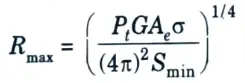
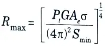
Q5. Define maximum range of radar.
Ans. The maximum range of radar Rmax is the distance beyond which the target cannot be detected. It occurs when the received signal power Pr just equals the minimum detectable signal Smin.
Q6. How the range to a target is determined in the radar ?
Ans. The time TR it takes the radar signal to travel to and from a target determines its range. Thus, the time required for the signal to go to a target at a distance R and return to the radar is 2R/c. The range to a target is then

Q7. How the constant false alarm rate receiver is used in radar?
Ans. When the noise is external to the radar, or if the clutter echoes are greater than the receiver noise, the threshold must be modified adaptively in order to keep the false alarm rate constant. A constant false alarm rate (CFAR) receiver does this.
Q8. What do you mean by false alarm ?
OR
Define the term false alarm and missed detection.
Ans. A. False alarm: If the threshold level is set too low, noise may exceed it and be misidentified as a target. This is known as a false alarm.
B. Missed detection: If the threshold is set too high, noise may not be large enough to produce false alarms, but weak target echoes may not be detected because they do not reach the threshold. This is referred to as a missed detection.
Q9. Define the term integration of radar pulses.
Ans. A radar often receives a large number of echo pulses from a target. Integration refers to the process of putting these pulses together to obtain a higher signal-to-noise ratio before making a detection judgement.
Q10. How MTI radar is different from other radar systems ?
Ans. Although both MTI radar and PD (Pulse Doppler) radar use the Doppler principle, the MTI radar determines moving targets by detecting the phase and amplitude of the received wave and comparing it to a saved replica of the original transmitted wave but at the opposite phase.
Q11. What is the principle of CW (continuous wave) radar ?
Ans. To identify moving targets, CW radar simply uses the Doppler frequency shift theory. Without the Doppler shift, the weak CW echo signal would not be noticed in the presence of a much greater signal. While receiving, a CW radar emits.
Q12. How Doppler filter is used in the CW radar?
Ans. 1. The Doppler filter permits the detector’s differential frequency to pass while rejecting higher frequencies.
2. It has a lower cut-off frequency to reduce transmitter leakage signals and clutter echoes from the receiver output.
3. A signal with a Doppler frequency fd located inside its pass band is passed by the Doppler filter.
Q13. Write the limitations of CW radar.
Ans.
- 1. Lack of isolation between transmitter and receiver.
- 2. Introduction of flicker-effect noise because the receiver is homodyne.
- 3. Lack of matched filter in the receiver.
- 4. No measurement of the range to the target.

Microwave and Radar Engineering Btech Quantum PDF, Syllabus, Important Questions
| Label | Link |
|---|---|
| Subject Syllabus | Syllabus |
| Short Questions | Short-question |
| Question paper – 2021-22 | 2021-22 |
Microwave and Radar Engineering Quantum PDF | AKTU Quantum PDF:
| Quantum Series | Links |
| Quantum -2022-23 | 2022-23 |
AKTU Important Links | Btech Syllabus
| Link Name | Links |
|---|---|
| Btech AKTU Circulars | Links |
| Btech AKTU Syllabus | Links |
| Btech AKTU Student Dashboard | Student Dashboard |
| AKTU RESULT (One View) | Student Result |
1 thought on “Aktu Btech Microwave and Radar Engineering KEC-074 Short Question, Notes, Quantum Book Pdf”