This blog provides a summary of the Fluid Mechanics exam for the school year 2022-2023. It will be useful for students studying for the test because it gives insight into prior years’ exam patterns and sorts of questions given.
Dudes 🤔.. You want more useful details regarding this subject. Please keep in mind this as well.

Important Questions For Fluid Mechanics:
*Unit-01     *Unit-02
*Unit-03    *Unit-04
*Unit-05    *Short-Q/Ans
*Question-Paper with solution 21-22
Short Questions for last year question paper Fluid Mechanic
a. Distinguish between gauge pressure and absolute pressure.
Ans. Gauge Pressure: A gauge pressure is a pressure that is measured using a pressure measuring device with the atmospheric pressure serving as the reference point.
Absolute Pressure: Absolute pressure is any pressure that is measured above the zero-point pressure.
b. What do you mean by Newtonian and non-Newtonian fluids ?
Ans. Newtonian fluids: Fluids that adhere to Newton’s law of viscosity are referred to as Newtonian fluids. The viscosity of these fluids does not alter with the rate of deformation.
Non-Newtonian fluids: Non-Newtonian fluids are defined as those that defy Newton’s viscosity law.
c. What is metacentric height? How is it determined ?
Ans. Metacentric Height: Metacentric height is the distance between a body’s centre of gravity and the metacentre.
It can be calculated by,


Metacentre: When the body is given a slight angular displacement, the line of action of the buoyancy force will intersect the normal axis of the body at the metacentre.
D. Define velocity potential function.
Ans. A scalar function of space and time called a “velocity potential function” is described as having a negative derivative with respect to each direction that corresponds to the fluid velocity in that direction. It is denoted by ф.


e. Explain difference between siphon and a normal tube.
Ans. Siphon Tube: When two reservoirs are separated by a hill or high level ground, a siphon a long, curved pipe is used to move liquid from one reservoir at a higher elevation to another reservoir at a lower level.
Normal Tube: A normal pipe is a closed conduit (often with a circular cross-section) used to transport fluids under pressure.
f. Differentiate between free and forced vortex.
Ans.
| S. No. | Forced Vortex Flow | Free Vortex Flow |
| 1. | It is one where the fluid mass is forced to rotate by some outside force. | It involves a rotating fluid mass without any externally applied contact forces. |
| 2. | It is also known as flywheel vortex or rotational vortex. | It is also known as potential or irrotational vortex. |
| 3. | Tangential velocity of any fluid particle is given by, v = ωr | Tangential velocity is given by V =c/r. |
| 4. | Ex: Rotation of water through the runners of a turbine. | Ex: Flow through bath tub or wash basin. |
g. Describe major and minor losses in pipes .
Ans. A. Major Energy Losses: This is due to friction and it is calculated by the following formulae,
- a. Darey – Weisbach formula
- b. Chezy’s formula
B. Minor Energy Losses:
- a. Sudden expansion of pipe
- b. Sudden contraction of pipe
- c. Bend in pipe
- d. Pipe fittings
- e. An obstruction in pipe
h. Define the displacement thickness.
Ans. The distance that the solid body’s boundary should be shifted by, measured perpendicular to the boundary, in order to make up for the flow reduction caused by the creation of boundary layers is known as the displacement thickness.
i. What do you mean by ‘Dimensional Analysis’ ?
Ans. It is a mathematical method for resolving various engineering issues that makes use of the study of dimensions.
j. Explain bluff and streamlined body.
Ans. Streamlined Body : A “streamlined body” is a body whose surface, when positioned in a flow, coincides with the streamlines.
Bluff Body : A “bluff body” is a body whose surface does not match the streamlines when it is positioned in a flow.
Section B: Long Question
a. An oil tanker of 2.5 x 2.5 m square cross section is 4 m long. Oil is filled upto a depth of 2 m. At what acceleration is the direction of its length the tanker be moved so that the corner A is exposed? What is then the net horizontal force acting on the tanker sides ? Take sp. gr. of oil as 0.8.
Ans. Given: Cross section of tank 2.5 mx 2.5 m, Length of tank 4m, Depth of oil= 2 m, Specific gravity of oil = 0.8.
To Find: i. Acceleration for exposed to corner A
ii. Horizontal force
1. The free surface of water in the tank will be along CA. a be the required horizontal acceleration,


2. Total force exerted by water on the face CE of the tank is


3. Force exerted by water on the face AB is zero, F2 = 0
4. Net horizontal force required = F1 – F2 = 61312.5-0 = 61312.5 N


b. Calculate the stream function for the given data :
i. Velocity components; u = x – 4y and v = -y -4x
ii. Velocity potential function, ф = 4x ( 3y – 4).
Ans. i. Given: u = x -4y and v = -y -4x
To Find: Stream function
1. Let 𝛙 = Stream function
2. The velocity components in terms of stream function are


4. Where C is a constant of integration which is independent of x but can be a function of y.


ii. Given: Velocity potential function,𝝓 = 4x (3y -4)
To Find: Stream Function
1. Velocity potential function,𝝓 =12xy – 16x


c. Calculate the discharge of water flowing through a pipe of 30 cm diameter placed in an inclined position where a venturi meter is inserted, having throat diameter of 15 cm. The difference of pressure between the main and the throat is measured by a liquid of specific gravity 0.6 in an inverted U-tube which gives a reading of 30cm. The loss of head between the main and the throat is 0.2 times the kinetic head of the pipe.
Ans.


5. Now applying Bernoulli’s equation at section (1) and (2), we get


6. Applying continuity equation at section (1) and (2), we get


d. Derive the momentum thickness for velocity distribution on the boundary layer given below:


Ans.


2. Momentum thickness is given by,


e. The variables controlling motion of floating vessel through water are the drag force F, the speed V, the length L, the density d, dynamic viscosity µ of water and acceleration due to gravity g. Determine the expression for F by dimensional analysis.
Ans. Given: Drag force, = F, Speed = V, Length = L, Density =ρ , dynamic viscosity =μ, Acceleration due to gravity = g
To Find: Expression for F by dimensional analysis.
Step1:
1. The resistance F is a function of:


3. Total number of variables, n = 6
4. m is obtained by writing dimensions of each variable as:


5. Thus the fundamental dimensions in the problem are M, L, T and hence
m = 3


Step 2: Selection of Repeating Variables:
1. Out of six variables F, V, l, μ, ρ, g three variables (as m = 3) are to be selected as repeating variables.
2. F is a dependent variable and should not be selected as a repeating variable.
3. These requirements are satisfied by choosing l, V, and p as recurring variables. Of the other five variables, one should have geometric property, the second should have flow property, and the third should have fluid property.
4. The repeated variables must collectively contain all fundamental dimensions equal to m, in this case 3, and must not alone create a dimensionless term.
5. Dimensions of l, V and p are L, LT-1, ML-3 and hence the three fundamental dimensions exist in l, V and p and also no dimensionless group is formed by them.
Step 3: Each π-term (= m + 1 variables) is written as given in eq. (5.18.1), i.e.,


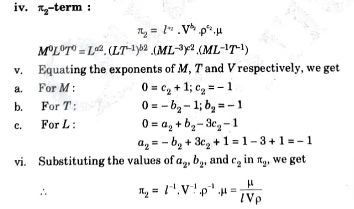
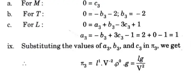
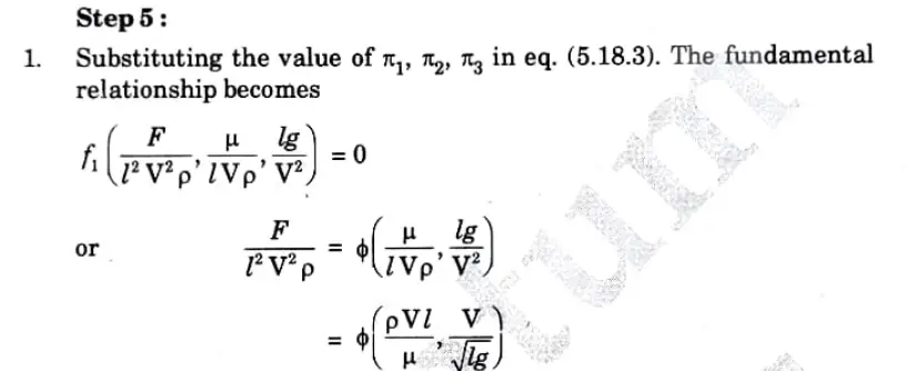
Step 4: Each π-term is solved by the principle of dimensional homogeneity, as follows:








Section C Long Question in Fluid Mechanics
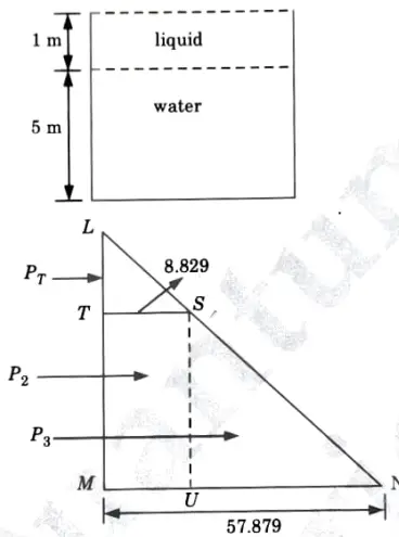
a. A tank contains water up to the lu~ight of 5 m above the base. An immiscible liquid of specific gravity 0.9 is filled on the top. of the water up to lm height. Calculate total pressure on one side of the tank and the position of center of pressure.
Ans. Given: Water height = 5 m, Height of immiscible liquid =1m, Specific gravity of immiscible liquid =0.9
To Find: Total pressure on one side and position of centre of pressure.
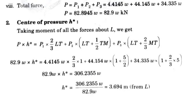
1. Total Pressure on One Side of Tank:
i. Total pressure (P) is calculated by drawing pressure diagram, which shown in Fig.
ii. Intensity of pressure on top, PL = 0
ii. Intensity of pressure on T,
iv. Intensity of pressure on the base,






b. Derive an expression for the depth of centre of pressure from free surface of a liquid of an inclined plane surface submerged into the liquid.
Ans. Inclined Plane Surface Submerged in Liquid:
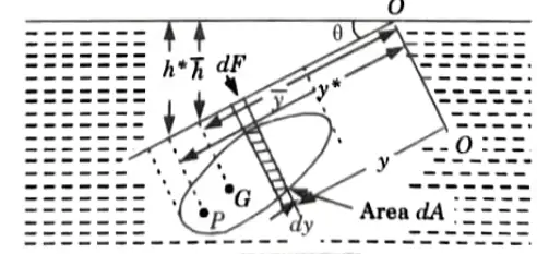


1. As seen in Fig., imagine a plane surface of any shape submerged in a liquid so that the plane of the surface forms a 0° angle with the liquid’s free surface.
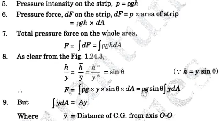
a. Total Pressure:
1. Let the plane of the surface, if produced, meet the free liquid surface at O.
2. Then O-O is the axis perpendicular to the plane of the surface.


4. Taking a small strip of area dA at a depth h’ from free surface and at a distance y from the axis O-O.


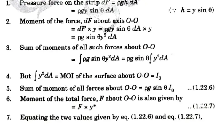
b. Centre of Pressure (h*):


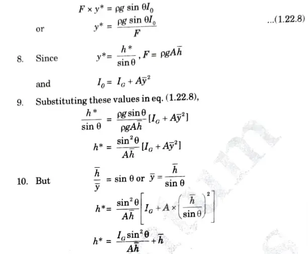


Section 4 : Long Question For Fluid Mechanics
a. Illustrate velocity. potential and stream function. Show that 3 D continuity equation for 3 D flow in Cartesian coordinates is given by,


Ans. 1. Velocity Potential Function:
1. The definition of the velocity potential is a scalar function whose negative derivative with respect to any fluid direction yields the velocity in that direction. It is denoted by ɸ (phi).
2. Thus mathematically the velocity potential is defined as:


Where u, v, and w are the components of velocity in the x, y, and z directions respectively.
3. The negative sign signifies that ɸ decreases with an increase values of x, y and z. In other words it indicates that the flow is always in the direction of decreasing ɸ.
2. Steam Function:
1. The steam function is a scalar function of space and time that produces the velocity component at a right angle to any direction from which its partial derivative is taken.
2. It is denoted by Ѱ(psi) and defined only for two dimensional flow. Mathematically, for steady clockwise flow,


3. The continuity equation for two-dimensional flow is


4. On substituting the values of u and v from eq. (2.9.1),
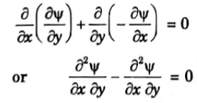


The flow may be rotational or irrotational.
5. The rotational component, is given by


6. Substituting the values of u and v from eq. (2.9.1) in the above rotational component


3. Continuity Equation :
1. Consider an elementary rectangular parallelopiped with sides of length δx, δy and δz as shown in Fig. 2.5.1.
2. Let the centre of the parallelopiped be at a point P(x, y, z) where the velocity components in the x,y and z directions are u, v and w respectively and p be the mass density of the fluid.
3. The mass of fluid passing per unit time through the face of area δyoz normal to the X-axis through point P, is


4. Then the mass of fluid flowing per unit time into the parallelopiped through the face ABCD is
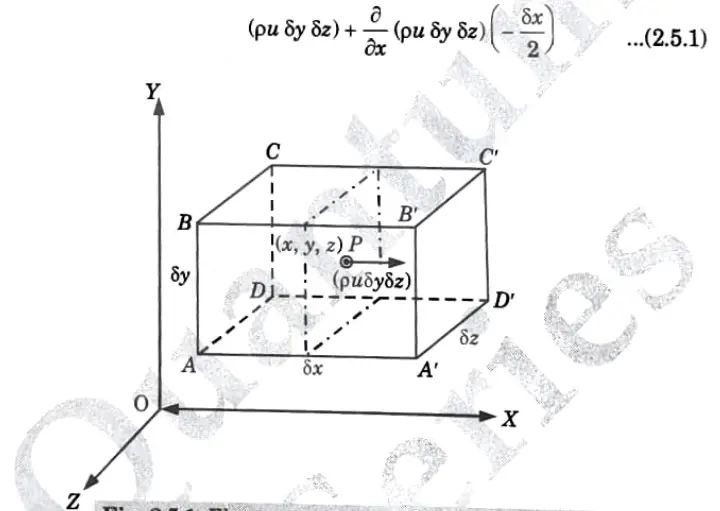


5. Similarly the mass of fluid per unit time out of the parallelopiped through the face ABCD is


7. Similarly the net mass of fluid that remains in the unit parallelopiped per time,


8. The net total amount of fluid that has stayed in the parallelopiped per unit time is derived by adding all these equations as


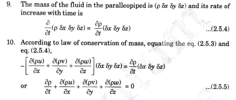


11. In its most general form, Eq. (2.5.5) provides the continuity equation in cartesian coordinates and is applicable to both compressible and incompressible fluids as well as steady and irregular flows, uniform and non-uniform flow.


b. The velocity potential function is given by an expression


i. Find the velocity component in x and y direction.
ii. Show that ɸ represent a possible case of flow.
iii. Find Stream function.
Ans. Given: Velocity potential function,


To Find : i. velocity component in x and y direction.
ii. ɸ represent a possible case of flow.
iii. Find Stream function.
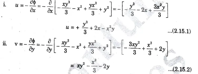
1. The velocity components u and v are given by,


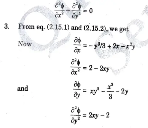
2. The given value of ɸ, will represent a possible case of flow if it satisfies the Laplace equation, i.e.,


3. Stream Function:
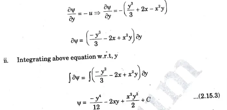
i. We know that,


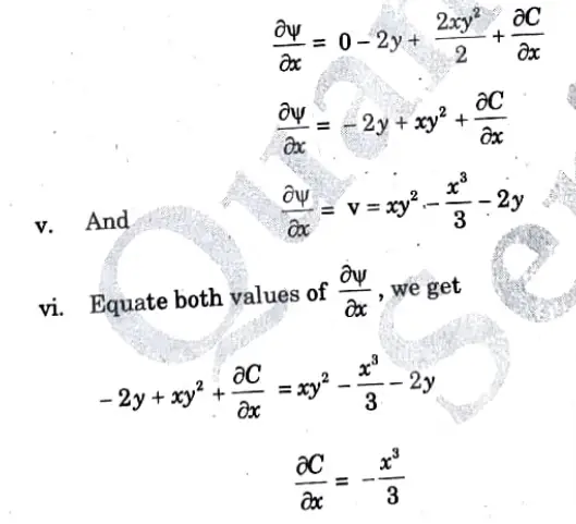
iii. Cis constant of integration which is independent of y but can be function of x.
iv. Differentiate eq. (2.15.3) w.r.t. x, we get


Section 5 : Long Question in Fluid Mechanics
a. Derive Euler’s equation of motion. Also derive the Bernoulli’s equation from Euler’s equation and mention the necessary assumptions for this equation.
Ans. i. Euler’s Equation :
1. As shown in Fig. consider a stream-line in which flow is taking place in S-direction.
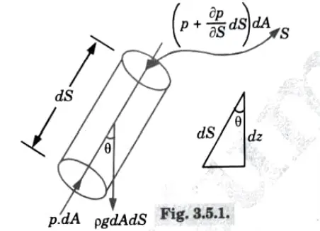


2. Consider a cylindrical element of cross section dA, length dS and Let θ is the angle between the direction of flow and the line of action of the weight of element.
3. The forces acting on the cylindrical elements are:
a. Pressure force pdA in the direction of flow.
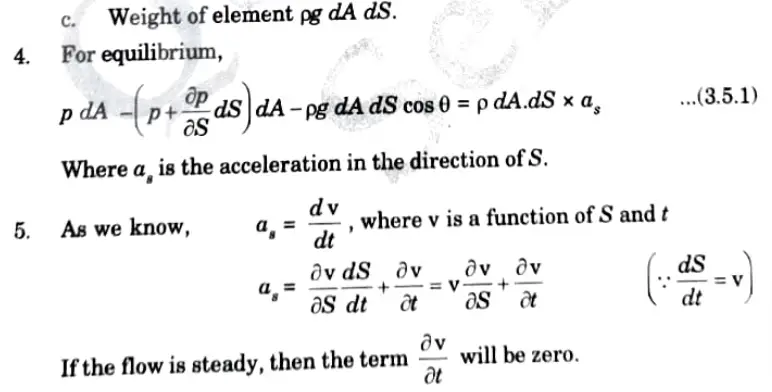


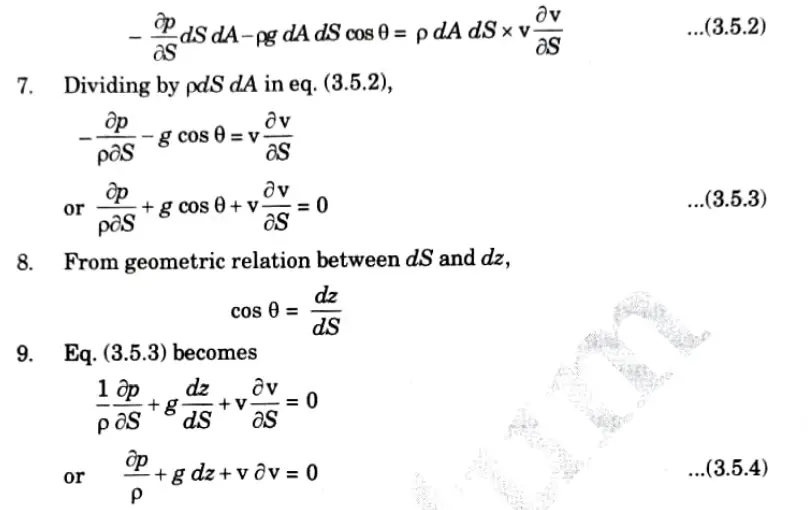


The eq. (3.5.4) is known as Euler’s equation of motion.
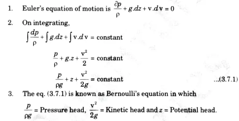
ii. Bernoulli’s Equation and Assumptions :


b. Describe :
i. Stream-lined body and bluff body.
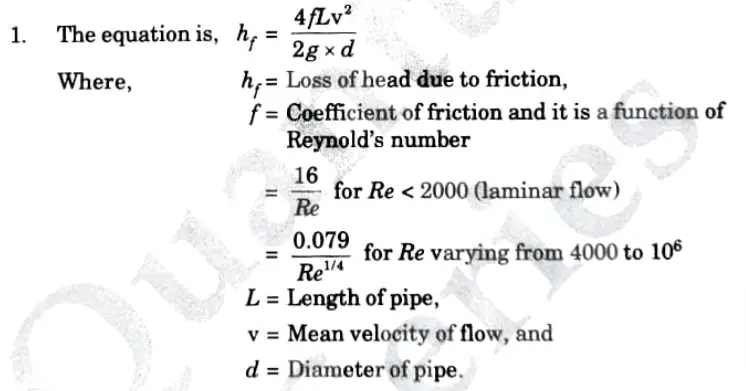
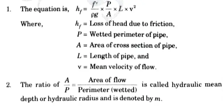
ii. Darcy-Weisbach formula and Chezy’s formula.
iii. Equivale~t pipe and compound pipe.
iv. Hydraulic gradient line and total energy line.
v. Reynold’s number and Euler’s number.
Ans. i. Streamlined Body and Bluff Body:
A. Streamlined Body:
1. A body whose surface coincides with the streamlines when placed in a flow is called a “streamlined body” (Fig.)
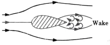


2. In this instance, flow separation solely affects the body’s trailing edge or backmost portion.
3. A streamlined body has a very small wake production zone, which causes the pressure drag to be relatively minimal.
4. Despite increased skin friction in such a body due to its bigger surface area, the overall result is a significant reduction in total drag.
5. A body may be streamlined at low speeds but not at higher speeds, and it may also be streamlined while it is at one position in the flow but not in another.
6. The blades of marine propellers, rotary axial flow machines, and aeroplane wings all have streamlined forms.
B. Bluff Body:
1. A body whose surface does not coincide with streamlines when placed in a flow is called a “bluff body” (Fig.)
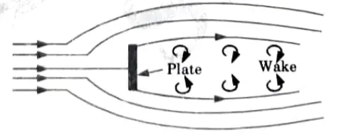


2. In this instance, there is significant boundary layer separation and a wake with sizable eddies.
3. The pressure drag that results from the massive wake generation is far more than the drag caused by friction on the body.
ii. Darcy-Weisbach and Chezy’s Formula :
a. Darcy Weisbach Formula for Head Loss due to Friction:


b. Chezy’s Formula for Loss of Head due to Friction in Pipes:


iii. Equivalent and Compound Pipe:
A. Equivalent Pipe:
1. This is described as a pipe with a uniform diameter that experiences head and discharge losses comparable to those of a composite pipe made up of many pipes of various lengths and diameters. Equivalent size of the pipe refers to the uniform diameter of the equivalent pipe.
2. The length of an equivalent pipe is the same as the total length of a composite pipe made up of various pipes.
B. Compound Pipe: Compound pipes are characterized as a pipe line made up of pipes that are joined end to end (in series) and have varying lengths and diameters.
iv. Hydraulic Gradient Line and Total Energy Line :
TEL: The definition of a total energy line (TEL) is a line that expresses the sum of the pressure head, datum head, and kinetic head of a flowing fluid in a pipe with respect to a reference line.
HGL: Hydraulic gradient line is defined as the line which gives the sum of pressure head (p/ω) and datum head (z) of a flowing fluid with respect to some reference line.
v. Reynold’s Number and Euler’s Number :
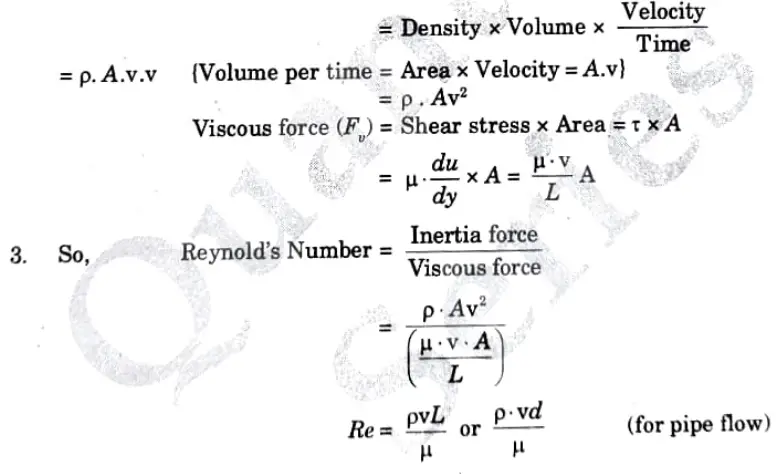
a. Reynold’s Number:
1. It is ratio of the inertia force to the viscous force.


2. Inertia force = Mass x Acceleration


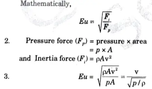
b. Euler’s Number (Eu):
1. It is the square root of the ratio of the inertia force to the pressure force of a flowing fluid.


Section 6: Long Question
a. Illustrate Prandtl’s mixing length concept to describe the turbulence during the fluid flows at high Reynold’s number.
Ans. A. Significance of Reynold’s Stress:
1. When a fluid is in turbulent flow, the shear stress (turbulent),


2. u’ and v’ are varying hence τ will also vary with time, therefore, taking the time average on both sides.


3. Reynold’s stress is used to determine the random orientation of fluid particles in turbulent flow.
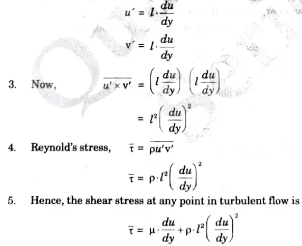
B. Prandt’s Mixing Length Theory for Turbulent Shear Stress:
1. According to Prandtl, the mixing length 1, is that distance between two layers in the transverse direction such that the lumps of fluid particles from one layer could reach the other layer and the particles are mixed in the other layer in such a way that the momentum of the particles in the X-direction remains same.
2. Assumptions in Prandtl’s theory


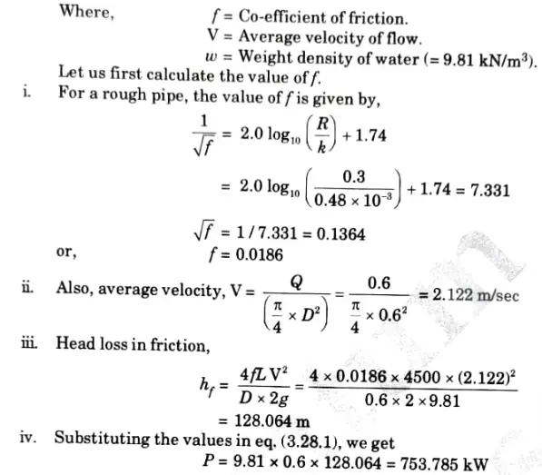
b. A pipe carrying water has average height of roughness of 0.48 mm. The diameter of pipe is 0.6m, length is 4.5km. The discharge of water is 0.6m3/sec. Determine the power required to maintain the flow if μ = 10-3N-sec/m2
Use the relation


Ans.


Power required to Maintain the Flow, P:




Section 7 : Long Question and answer
a. Illustrate terminal velocity of the body. Also illustrate the drag on a sphere and on a cylinder.
Ans. A. Terminal Velocity and Drag on Sphere:
a. Terminal Velocity:
1. The term “Terminal velocity” refers to the highest constant speed that a falling body (such as a sphere or a composite body like a parachute and a person) will be travelling at.
2. The body’s velocity increases as it falls from rest in the atmosphere as a result of the acceleration of gravity.
3. The drag force, which opposes the motion of the body, likewise increases as velocity rises.
4. A stage is reached wB be equal to the weight of the body.
5. The body will then be moving at a constant speed and there will be no net external force acting on it.
6. This constant speed is called terminal velocity of the falling.
b. Drag on a Sphere:
1. Consider a flow of real fluid passing with velocity U over a sphere having diameter D, density of fluid is ρ and viscosity is μ.
2. To calculate the overall drag on a sphere submerged in a fluid with a Reynolds number less than 0.2, Stokes devised a mathematical equation.
3. Stokes states that all inertia forces acting on the fluid are presumed to be negligible for Reynolds numbers less than 0.2; only viscous forces are to be taken into account.
4. According to Stokes,
Total drag acting on sphere is, FD=3πµDU
5. Two thirds of the total drag is caused by skin friction, while the remaining third is caused by pressure drag.


B. Drag on Cylinder :
1. Consider a cylinder with dimensions of D and L that is submerged in a fluid with kinematic viscosity of v and free flow velocity of u.
2. In comparison to the viscous force, inertia forces are insignificant if the flow’s Reynold’s number is less than 0.2.
3. The inertia force increases along with Reynold’s number, which causes the flow pattern to become asymmetrical with respect to the axis perpendicular to the flow direction.
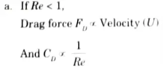
4. From experiment following observations are to be made


b. Discuss geometric, kinematic and dynamic similarly. Are these equations obtainable?
Ans. A. Geometric Similarity:
1. If all of the related linear dimensions in the model and prototype have the same ratio, there is said to be geometric resemblance between them.


3. For geometric similarity between model and prototype, we must have the relation,


Where Lr is called the scale ratio.
4. For area’s ratio and volume’s ratio the relation should be as given below:


B. Kinematic Similarity:
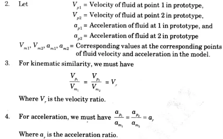
1. Kinematic similarity refers to how motion in a model and prototype is similar. If the ratios of the velocity and acceleration at the respective positions in the model and the prototype are the same, then the model and prototype are said to have kinematic similarity.


C. Dynamic Similarity:
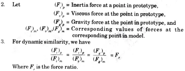
1. Dynamic similarity refers to how similarly the forces acting on the prototype and model are. Thus, if the ratios of the respective forces acting at the corresponding places are the same, then dynamic similarity is said to exist between the model and the prototype.


D. Attainable or Not: The model must be identical to the prototype, however it may be scaled by a fixed amount. Thus, while necessary, kinematic and geometric similarities are not enough to guarantee dynamic similarity. Geometric and kinematic similarity can thus be attained, but dynamic similarity cannot.


Important Question with solutions | AKTU Quantums | Syllabus | Short Questions
Fluid Mechanics Btech Quantum PDF, Syllabus, Important Questions
| Label | Link |
|---|---|
| Subject Syllabus | Syllabus |
| Short Questions | Short-question |
| Important Unit-1 | Unit-1 |
| Important Unit-2 | Unit-2 |
| Important Unit-3 | Unit-3 |
| Important Unit-4 | Unit-4 |
| Important Unit-5 | Unit-5 |
| Question paper – 2021-22 | 2021-22 |
Fluid Mechanics Quantum PDF | AKTU Quantum PDF:
| Quantum Series | Links |
| Quantum -2022-23 | 2022-23 |
AKTU Important Links | Btech Syllabus
| Link Name | Links |
|---|---|
| Btech AKTU Circulars | Links |
| Btech AKTU Syllabus | Links |
| Btech AKTU Student Dashboard | Student Dashboard |
| AKTU RESULT (One VIew) | Student Result |
