With the help of our AKTU question paper and solution, you can unleash the power of Digital Signal Processing. For a deeper comprehension of signal analysis and manipulation, see our quantum notes and thorough PDFs.
Dudes 🤔.. You want more useful details regarding this subject. Please keep in mind this as well.

Important Questions For Digital Signal Processing:
*Quantum          *B.tech-Syllabus
*Circulars           *B.tech AKTU RESULT
* Btech 3rd Year
Section A: Digital Signal Processing Important Short Questions
a. Define the recursive and non-recursive systems.
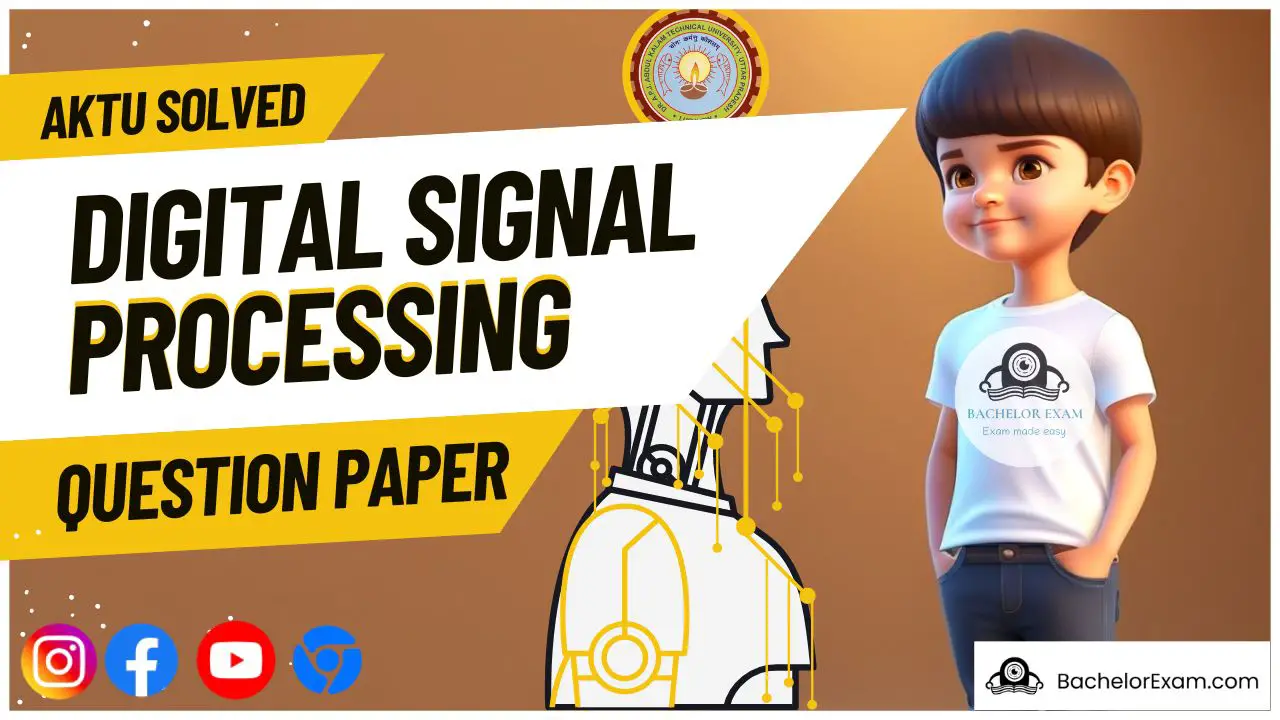
Ans. Recursive system: Recursive systems are those in which the output y(n) of the system depends on both the past and present inputs as well as the past output.
Mathematically,
Non-recursive system: It is referred to as a non-recursive system when the output y(n) of the system depends on both the current and previous inputs.
Mathematically,

b. Enlist the condition for Linear Phase FIR digital with 5 number of samples.
Ans. Condition for Linear Phase FIR digital with 5 number of samples is:
The first coefficient is same as the last (5); the second coefficient is the same as the next to last etc.
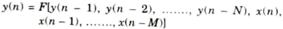
c. Differentiate Butterworth Low Pass Filter with Chebyshev LPF in terms of Filter Order.
Ans. Butterworth filter: Transition band is broader than Chebyshev for given order.
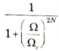
Chebyshev filter: Transition band is narrower than Butterworth for given order.
d. Evaluate the value of C3(x), Chebyshev Polynomial.
Ans. 1. We know that a Chebyshev polynomial of degree N is defined as

2. The recursive formula for the Chebyshev polynomial of order N is given as
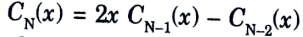
3. Thus, for a chebyshev filter of order 3, we obtain

e. Demonstrate the term Gibb’s phenomenon with schematic diagram.
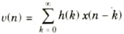
Ans. 1. The impulse response of FIR filter in terms of rectangular window is given by,

2. The frequency response of the filter is obtained by taking Fourier transform of eq. (3.5.1)

This shows that the frequency response of FIR filter is equal to the convolution of desired frequency response, Hd(𝜔) and the Fourier transform of window function.
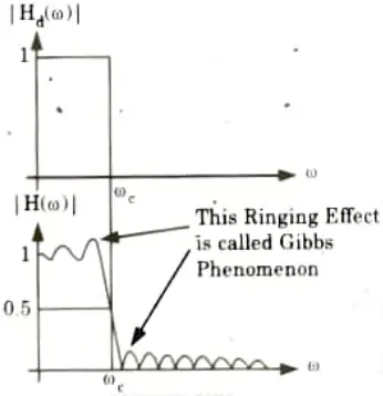
3. Sidelobes are present in the frequency response. As a result, ringing can be seen in the FIR filter’s frequency response. This ringing is most noticeable close to the filter’s band edge.
4. The Gibbs phenomenon refers to the oscillatory behaviour (i.e., ringing effect) at the filter’s band edge.
f. Evaluate the DFT for the sequence [1, 2, 7, 3].
Ans. Given: z(n) = [1, 2,7, 3]
To Find: DFT
1. DFT of a finite duration sequence x(n) is define as0
![Evaluate the DFT for the sequence [1, 2, 7, 3]](https://bachelorexam.com/wp-content/uploads/2023/07/image-278.png)
Here, N = 4
2. For k = 0,
![Evaluate the DFT for the sequence [1, 2, 7, 3]](https://bachelorexam.com/wp-content/uploads/2023/07/image-279.png)
3. For k = 1,
![Evaluate the DFT for the sequence [1, 2, 7, 3]](https://bachelorexam.com/wp-content/uploads/2023/07/image-281.png)
4. For k = 2,
![Evaluate the DFT for the sequence [1, 2, 7, 3]](https://bachelorexam.com/wp-content/uploads/2023/07/image-282.png)
5. For k = 3,
![Evaluate the DFT for the sequence [1, 2, 7, 3]](https://bachelorexam.com/wp-content/uploads/2023/07/image-283.png)
h. Find out the total no of Complex additions and Complex multiplications required for calculating 8-point Conventional DFT and by using butterfly structure DIT-FFT.
Ans. The 8-point DFT therefore requires 8 x 8 = 64 complex multiplications.
And require 8(8 – 1) = 8 x 7 = 56 complex additions.
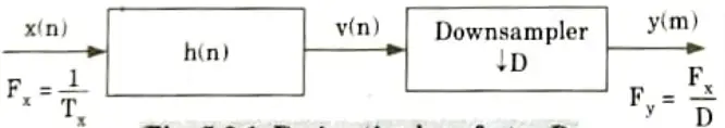
i. Explain the term Decimation with suitable example.
Ans. The process of reducing the sampling rate by a factor D(downsampling by D) is called decimation.
j. Find the output of the sequence [1 2 3] after up sampling by a factor N = 3.
Ans. Given, x(n) = [1, 2, 3]
And, N = 3
Output y(n) = x(n/3)
y(n) = [1, 0, 0, 2, 0, 03, 0, 0]
Section B: Digital Signal Processing Aktu Important Questions
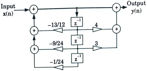
a. Realize the given H(z) for using ladder structure.
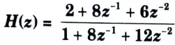
Ans. 1. For the given system, obtain the Routh array
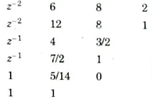
2. The ladder structure parameters are
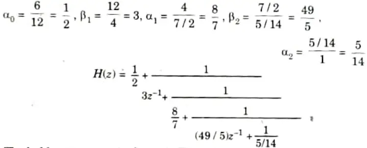
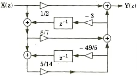
3. The ladder structure is shown in Fig.
b. Design Digital Butterworth filter to satisfy the following constraints using bilinear transformation method, the sampling interval is 2 second: assume missing dataif required:
Ans. Given:

To Design: Butter worth filter.
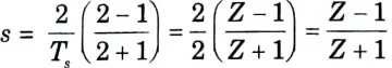
Step 1: For bilinear transformation, we have
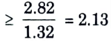
Step 2: Order of filter, N is given by,
Thus, we can take N = 2 (approx)
Step 3: Cut-off frequency can be determined by,
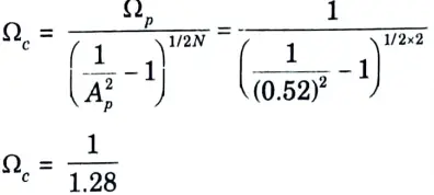
Step 4: The poles of H(s) are given by
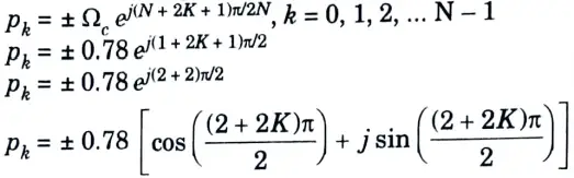
Range of K is 0 to N – 1 thus K = 0
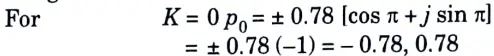
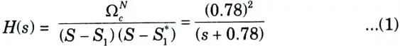
Step 5: Calculation of H(s): For the stability of filter, select the poles on the LHS of s-plane
So we will select the pole s = – 0.867.
The system function of second order Butterworth filter given as
Step 6: The transfer function of digital filter is obtained by putting
put value of s in eq. (1), we get
c. Explain the concept of the Limit Cycle Oscillations and dead band effect with suitable example.
Ans. 1. There are two types of limit cycles, zero input limit cycle and overflow limit cycle. Zero input limit cycles are usually of lower amplitudes in comparison with overflow limít cycles.
2. Let us consider a system with the difference equation

with zero input, i.e., x(n) = 0 and initial condition y(-1) = 10.
3. A comparison of the precise values of y(n), as given by eq. 3.19.1, obtained using unquantized arithmetic, and the rounded value of y(n), as obtained arithmetically.
4. The unquantized output y(n), given zero input, decays exponentially to zero with increasing.
5. However the output y(n) gets sucked at a value of two and never degrades further.
6. As a result, even in the absence of any input, the output is limited. The term “zero input limit cycle effect” refers to this.
7. It can also be seen that tor any value of the input condition |y(-1)| ≤ 2, the output y(n) = y(-1), n ≥ 0, when the input is zero. Thus, the deadband in this case is the interval [-2, 2].
8. The effects of limit cycles in first-order and second-order systems were studied by Jackson using an “effective value” model. It was realised that limit cycles can occur only if the result of rounding leads to poles on the unit circle.
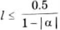
9. Consider the first-order difference equation y(n) = x(n) – [ay(n – )]* where [.]* denotes rounding to the nearest integer with x(n) =0, n ≥ 0. The deadband in which limit cy les can exist is the range [-l, l] where l is the largest integer satisfying,
10. If a is negative, the limit cycle will have constant magnitude and sign. If a is positive, the limit cycle will have constant magnitude by alternating Sign.
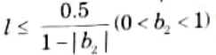
11. Consider the second-order system with the difference equation

12. The deadband for this system is the region |l-1,1| where l is the largest integer satisfying
d. Calculate the circular convolution using graphical method for x(n) = [1, 2, 3, 4] and h(n) = [4, 3, 2, 1]
Ans. Given: x(n) = [1, 2,3, 4] and h(n) [4,3, 2, 1]
To Find: Circular convolution.
1. Circular convolution,
![Calculate the circular convolution using graphical method for x(n) = [1, 2, 3, 4] and h(n) = [4, 3, 2, 1]](https://bachelorexam.com/wp-content/uploads/2023/07/image-290.png)
where, m = 0, 1, 2, 3
![Calculate the circular convolution using graphical method for x(n) = [1, 2, 3, 4] and h(n) = [4, 3, 2, 1]](https://bachelorexam.com/wp-content/uploads/2023/07/image-289.png)
y(0) = 1 x 4 + 2 x 1 + 3 x 2 + 4 x 3
= 4 + 2 + 6 + 12 = 24
![Calculate the circular convolution using graphical method for x(n) = [1, 2, 3, 4] and h(n) = [4, 3, 2, 1]](https://bachelorexam.com/wp-content/uploads/2023/07/image-288.png)
y(1) = 1 x 3 + 2 x 4 + 3 x 1 + 4 x 2
= 3 + 8 + 3 + 8 = 22
![Calculate the circular convolution using graphical method for x(n) = [1, 2, 3, 4] and h(n) = [4, 3, 2, 1]](https://bachelorexam.com/wp-content/uploads/2023/07/image-287.png)
y(2) = 1 x 2 + 2 x 3 + 3 x 4 + 4 x 1
= 2 + 6 + 12 + 4 = 24
5. For m = 3,
![Calculate the circular convolution using graphical method for x(n) = [1, 2, 3, 4] and h(n) = [4, 3, 2, 1]](https://bachelorexam.com/wp-content/uploads/2023/07/image-286.png)
y(3) = 1 x 1 + 2 x 2 + 3 x 3 + 4 x 4
= 1 + 4 + 9 + 16 = 30
6. Therefore, y(n) = {24, 22, 24, 30}
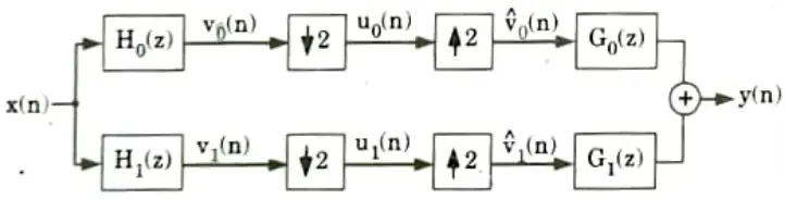
e. Summarize QMF and Explain analytical and synthesis filter bank with aliasing free filter bank.
Ans. 1. The subband signals are down sampled before processing. The signals are up sampled after processing.
2. The structure used for this is known as Quadrature Mirror Filter (QMF) bank.
3. If the decimation and interpolation factors are equal, then the characteristics of x(n) will be available in y(n) if the filters are properly selected.
4. If this properly is satisfied, then the filter bank can be called as a critically sampled filter bank.
5. To list a few applications where QMF filters are used.
i. Efficient coding of the signal x(n)
ii. Analog voice privacy for secure telephone communication.
6. The two-channel QMF filter bank is shown in Fig. The analysis filter H0(z) is a low-pass filter and H1(z) is a high-pass filter.
7. The cut-off frequency is taken as 𝜋/2 for these filters.
8. The subband signals {vke,(n)} are down sampled. After down sampling. these signals are processed (encoded).
9. In the receiving side the signals are decoded, up-sampled and then passed through the synthesis filters G0(z) and G1(z) to get the output y(n).
10. The encoding and decoding processes are not shown in Fig.
11. For perfect reconstruction, the QMF filter banks should be properly selected.
Section 3: Digital Signal Processing Aktu Important Notes
a. Describe the linear phase FIR system and for h(n) = [1/2, 1/8, 1/5, 1/3, 1/2]. Realize H(a) of the Linear phase FIR system for the given impulse response.
Ans. A. Linear phase FIR system:
1. For linear phase FIR filter, signal falling entirely in the passband will be reproduced with the delay equal to the slope of the phase curve.
2. One of the most important features of FIR digital filters is that they can be designed to have exactly linear phase.
B. Numerical:
1. h(n) = [1/2, 1/3, 1/5, 1/3, 1/2]
2. N is odd then H(z) is,
![Describe the linear phase FIR system and for h(n) = [1/2, 1/8, 1/5, 1/3, 1/2].](https://bachelorexam.com/wp-content/uploads/2023/07/image-310.png)
![Describe the linear phase FIR system and for h(n) = [1/2, 1/8, 1/5, 1/3, 1/2].](https://bachelorexam.com/wp-content/uploads/2023/07/image-311.png)
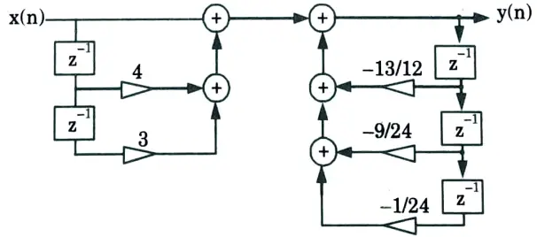
b. Find out the direct form-I and direct form-II realization of a discrete-time system represented by the transfer function

Ans.
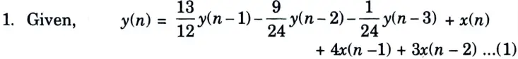
2. Taking z-transform of both side of eq. (1)
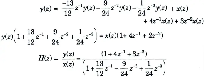
i. Direct form I:
ii. Direct form II:
Section 4: Chebyshev Digital LPF Filter Quantum Notes
a. Design Chebyshev Digital LPF filter to satisfy the following constraints using Impulse Invariant method.

Ans. Given:
To Find: Chebyshev filter.
7. N = 2
8. Poles are
10. Numerator of

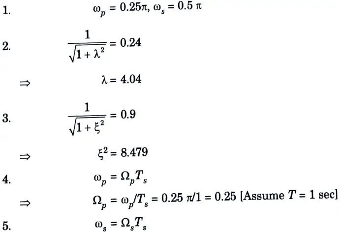
b. Design Chebyshev Digital LPF filter to satisfy the following constraints using Bilinear Transformation method, assume that the sampling time is one second.
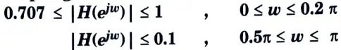
Ans. Given:


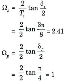
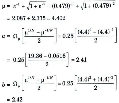
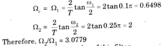
1. Determination of the analog filter’s edge frequencies.
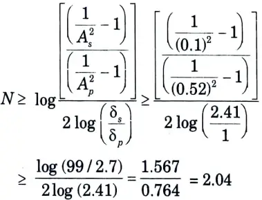
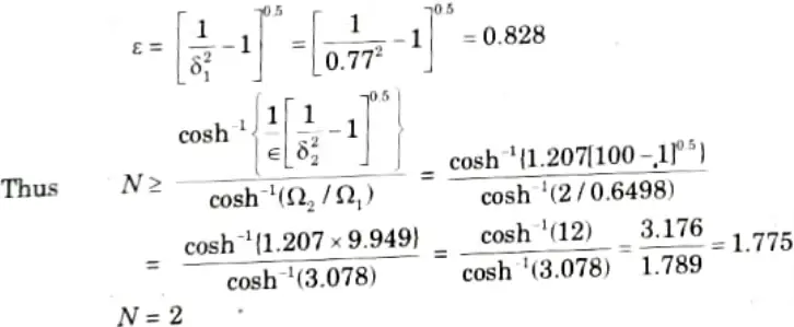
2. Determination of the order of this filter.
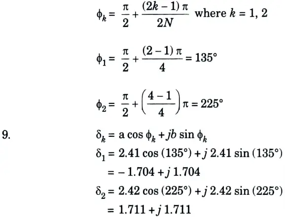
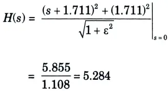
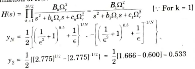
3. Determination of H(s)
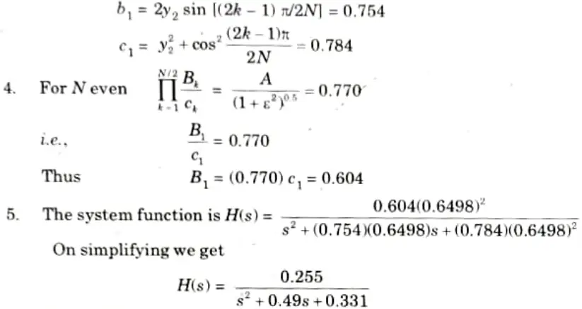
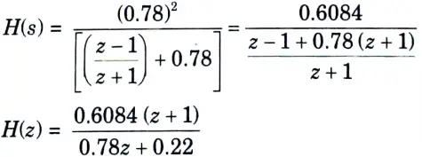
6. Determination of H(z) using bilinear transformation
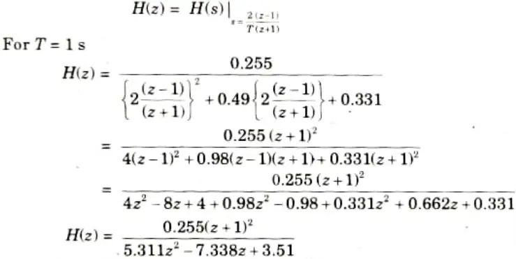
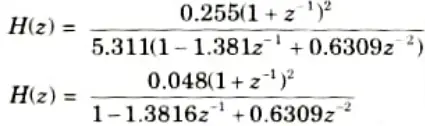
7. By dividing z2 in numerator and denominator, we get
Section 5: Digital Signal Processing Aktu Important Questions
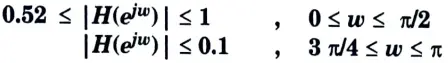
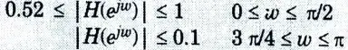
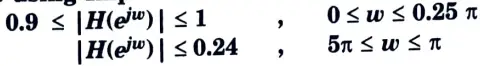
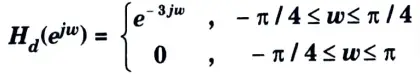
a. A low Pass filter is to be designed with the following specifications:
Using Rectangular window function, find the Filter coefficients and Frequency spectrum of the designed filter.
Ans.
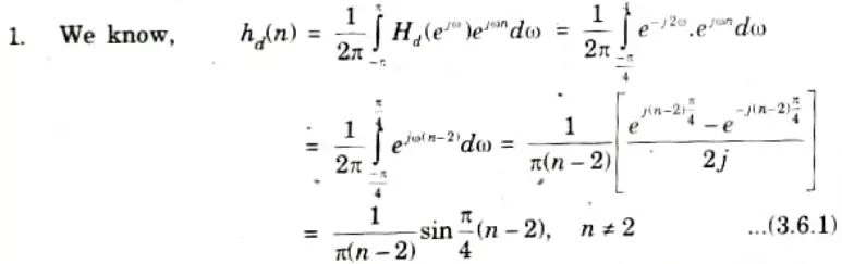
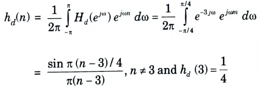
2. For n = 2, the filter coefficient can be obtained by applying L-Hospital’s rule to eq. (3.6.1)
Thus, hd(2) = 1/4
3. The other filter coefficients are given by
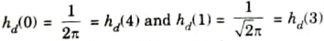
4. The filter coefficients of the filter would be then
h(n) = hd(n) w(n)
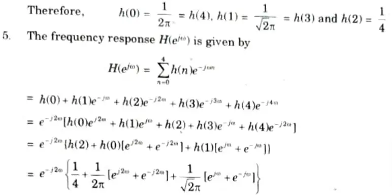
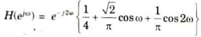
6. The frequency response of the designed low pass filter is then,
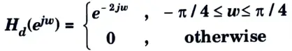
b. Designm a filter with
Using Hamming window with M = 7.
Ans. Given:

To Design: Filter.
1. The filter coefficients are given by,
The filter coefficients are,
hd(0) = 0.0750, hd(1) = 0.159, hd(2) = 0.247
hd(3) = 0.25, hd(4) = 0.225, hd(5) =0.159, hd(6) = 0.74
2. The Hamming window function is
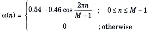
Therefore, with M = 7,
𝜔(0) = 0.08, 𝜔(1) = 0.31, 𝜔(2) = 0.77, 𝜔(3) = 1,
𝜔(4) = 0.77, 𝜔(5) = 0.31, 𝜔(6) = 0.08
3. The filter coefficients of the resultant filter are then
h(n) = hd(n) 𝜔(n), n = 0,1, 2, 3, 4, 5, 6
Therefore, h(1) = 0.006, h(1) = 0.04929, h(2) = 0.19019
h(3) = 0.25, h(4) = 0.17325, h(s) = 0.5565
h(6) = 0.592
4. The frequency response is given by,

Section 6: DIT FET algorithm Important Notes
a. Derive and solve the DIT FET algorithm for 8 numbers of samples.
Ans. 1. Assuming radix-2 FFT algorithm in DIT-FFT algorithm, the N-point DFT is divided into two N/2-point DFT in 2nd stage, then into N/4-point DFT in 3rd stage and so on until the 2-point DFT is not achieved.
For radix-2 FFT
N = 2.2.2…2l = 2l.
2. Let z(n) is the sequence of N values. The given sequence x(n) is decimated (broken) into two N/2-point DFTs consisting of the even numbered values of z(n) and the odd numbered values of x(n).
3. The N – point DFT of sequence x(n) is given as
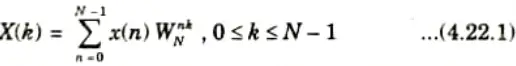
4. In eq. (4.22.1) breaking x(n) into even and odd numbered values, we have
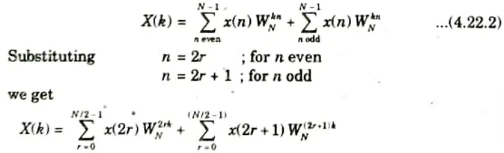
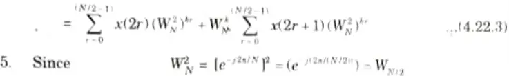
Thus eq. (4.22.3) can be written as

6. In eq.(4.22.4) the first part is the N/2-point DFT of x(2r) say A(k), and x(2r + 1) is B(k).
Then eq. (4.22.4) can be written as

7. The sum of A(k) and B(k) are computed for 0 ≤ k ≤ N/2- 1 because A(k) and B(k) are considered periodic with the period N/2. For periodicity the eq. (4.22.5) can be written as
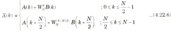
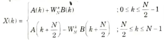
8. Using the symmetry property of WNk+N/2 = -WNk then eq. (4.22.6) will become
Section 7: LMS Algorithm Aktu Important Questions
a. Explain the block diagrammatic presentation of DSP processor, with its architecture, addressing formats and its commercial usages.
Ans. Fig. shows the basic elements of digital signal processing system. Input is given through analog digital converter and output is obtained through digital to analog converter.
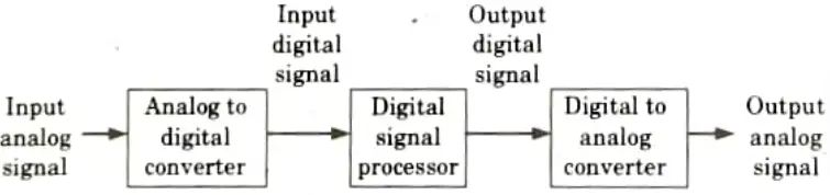
Basic elements of digital signal processing:
- i. Analog to digital converter:
- 1. An analogue to digital conversion is performed by an AD converter. A DSP system processes this signal.
- 2. During the digitizing process, the A/D converter determines the sampling rate and quantization error.
- ii. Digital signal processor:
- 1. It processes digital data by amplification, attenuation, filtering, spectrum analysis, feature extraction, etc.
- 2. To function, the digital signal processor needs an ALU, a shifter, serial ports, interrupts, address generators, etc.
- 3. In contrast to general purpose microprocessors, the DSP processor implements DSP functions using specific architectural features.
- iii. Digital to analog converter:
- 1. Restoring some of the processed signals to their analogue state is necessary. For instance, analogue signals of sound, picture, and video are necessary. Hence, a digital to analogue converter receives the output of the DSP processor.
- 2. A D/A converter converts a DSP processor’s digital output to its analogue equivalent. These analogue outputs contain processed signals.
b. Write a short note on LMS algorithm.
Ans. LMS algorithm:
1. In practical applications of adaptive filtering, a fixed step size algorithm is required for
i. Easier implementation and
ii. Tracking time variant signal statistics.
2. The algorithm proposed by Widrow and Hoff is
HM(n + 1) = hM(n) + 𝚫e(n) X*M(n)
where 𝚫 is the fixed step size.
3. The main advantages of LMS algorithm is that it requires simple computation. But the price paid for this is
i. Slow convergence and
ii. Single adjustable parameter 𝚫 for controlling the convergence rate.
5 thoughts on “Digital Signal Processing: Quantum Notes Solved Question Paper Aktu”