
With our AKTU question paper and solution, learn about the world of Analog and Digital Communication. To learn more about contemporary communication systems, explore detailed PDFs and quantum notes.
Dudes 🤔.. You want more useful details regarding this subject. Please keep in mind this as well.

Important Questions For Analog and Digital Communication:
*Quantum          *B.tech-Syllabus
*Circulars           *B.tech AKTU RESULT
* Btech 3rd Year
Section A: Analog and Digital Communication Aktu Short Questions
a. Define modulation, amplitude modulation and angle modulation.
Ans.
- A. Modulation: Modulation is the process through which a signal’s carrier property is changed in line with the current value of the baseband or modulating signal.
- B. Amplitude modulation: Amplitude Modulation (AM) is a type of modulation in which the frequency of the carrier is maintained constant while the amplitude of the carrier is made proportional to the instantaneous amplitude of the modulating voltage.
- C. Angle modulation: It involves maintaining a fixed carrier amplitude while altering the overall phase angle of a carrier wave in accordance with the current value of the modulating signal.
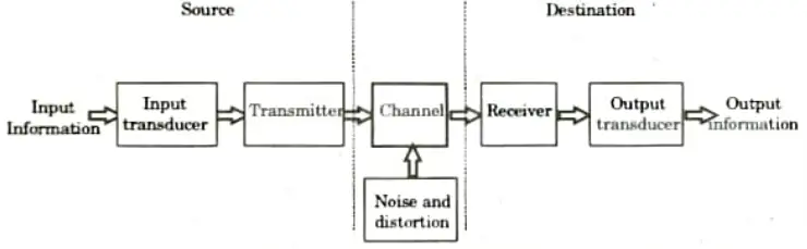
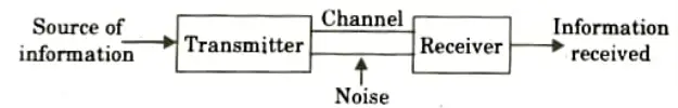
b. Draw the block diagram of communication system and mention the name of each block.
Ans.
c. What is frequency deviation of FM signal ?
Ans. The instantaneous frequency of FM signal varies with time. The maximum change in instantaneous frequency from the average i.e., 𝛚c, is called frequency deviation.
d. Define modulation index and percentage modulation in case of FM.
Ans. A. Modulation index: The ratio of the frequency deviation 𝚫f to the modulation frequency fm is called modulation index.
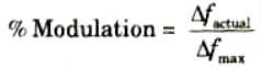
B. Percentage modulation: The ratio of actual frequency deviation to the maximum allowable frequency deviation is percentage of modulation in FM.
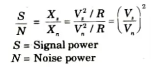
e. Explain briefly, signal to noise ratio.
Ans. It is defined as the ratio of signal power to noise power at the same point. Therefore,
f. Discuss Nyquist criteria for sampling.
Ans. 1. The sampling rate should be at least twice the bandwidth of the signal, in order to fully reconstruct the signal.
2. Otherwise, there will be aliasing effect.
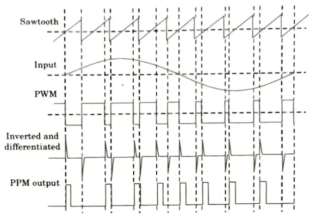
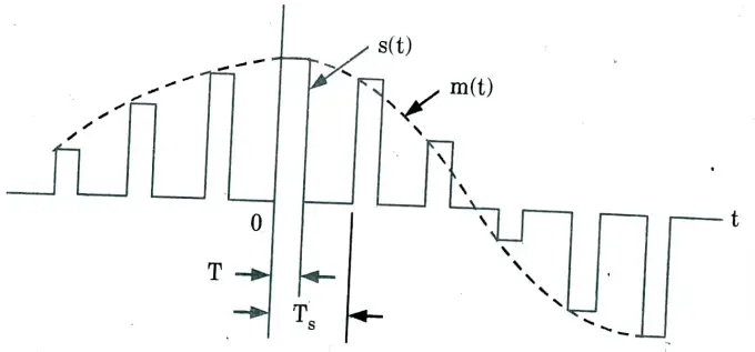
g. Draw the signal waveform of PAM, PWM and PPM.
Ans. A. PAM:
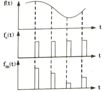
B. PWM and PPM:
h. Explain briefly, quantization process.
Ans.
- 1. Approximation or rounding off is the process of quantization. The quantizer block is applied with the PCM sampled signal.
- 2. The quantizer approximates the sampled signal by converting it to a quantized signal that has just a limited range of previously determined voltage values.
- 3. The nearest predetermined standard voltage level is approximated or rounded off for each sampled value at the quantizer’s input.
i. What do you understand by Shannon Hartley theorem?
Ans. 1. The Shannon Hartley theorem is a companion theorem to Shannon’s theorem that pertains to channels with gaussian noise.
2. The channel capacity of a white, bandlimited gaussian channel is
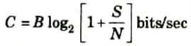
where, B is the channel bandwidth, Sis the signal power, and Nis total noise within the channel bandwidth ie., N = 𝛈𝛃 with 𝛈/2, the power spectral density.
3. It is crucial to understand this theorem. First, gaussian channels are typically encountered in physical systems. A lower constraint on the performance of a system running over a non-gaussian channel is frequently provided by the results found for a gaussian channel.
j. What is electronic commutator in TDM system?
Ans. Commutator is usually implemented using electronic switching circuitry. Mainly two functions are done by commutator.
a. To take a narrow sample of each of the N input messages at a rate fs that is slightly higher than 2W, where W is the cutoff frequency of the anti-aliasing filter.
b. To sequentially interleave these N samples inside the sampling interval Ts.
Section B: Analog and Digital Communication Important Quantum Notes
a. Why is modulation needed ?
Ans. 1. Multiplexing:
- i. Multiplexing is the process of sending many messages over the same channel. Since the signals’ basebands (spectrums) are similar, they will interfere with one another if delivered without modulation.
- ii. However, employing multiplexing techniques of which there are two varieties: frequency division multiplexing and temporal division multiplexing the signals can be sent without interfering.
2. Practicability of antenna:
- i. When free space is used as the communication medium, the message signals are transmitted via an antenna at the transmitter.
- ii. For affective transmission the height of the antenna should be of the order of the wavelength to be transmitted. Therefore, if the wavelength of the signal is 5 kHz then height of the antenna should be
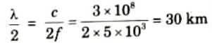
which is impracticable.
- iii. Modulation, which offers frequency shifting, helps lower the antenna’s height. Modulation uses higher frequency pulses with short wavelengths.
- iv. Therefore, if an audio frequency is translated to radio frequency of 1 MHz, then height of the antenna is:
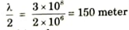
which is practically achieved.
3. Narrowbanding:
- i. Even if we assume that the antenna’s height is practical, the audio signals that are sent range in frequency from 50 kHz to 10 kHz, with a 200:1 ratio between the highest and lowest wavelengths.
- ii. So a single antenna cannot receive all the signal. Now if the audio signals are translated to radio range frequency of 1 MHz, then ratio becomes
which is approximately unity. So a single antenna can receive all the signals.
b. Differentiate between narrowband FM and wideband FM with their frequency spectrum and suitable mathematical expressions.
Ans. A. Narrowband FM:
1. When kf i.e., frequency sensitivity is small, the bandwidth of FM is narrow.
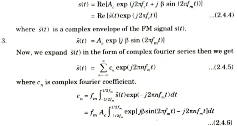
2. We know FM signal is given by

where 𝛃 is modulation index.
Expanding the relation of eq. (2.4.1)
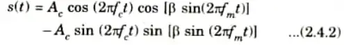
3. Assuming that the modulation index 𝛃 is small as compared to 1 radian then the approximations
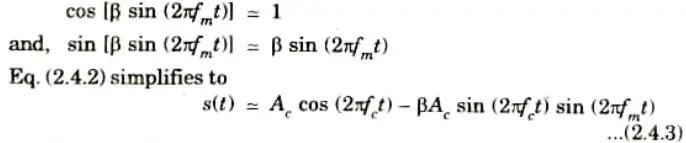
Eq. (2.4.3) defines the approximate form of a narrowband FM signal produced by a sinusoidal modulating signal
B. Wideband FM:
1. When kf has an appreciable value, then the FM signal has a wide bandwidth.
2. In order to determine the spectrum of the single-tone FM signal otf eq. (2.4.1) for an arbitrary value of modulation index 𝛃. We assume that the carrier frequency fc is large enough therefore,
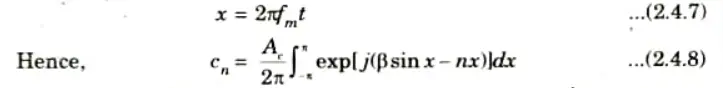
4. Defining a new variable:
5. The integral on the right hand side is recognized as the nth order Bessel function of the first kind and argument 𝛃. This function is commonly denoted by Jn(𝛃).
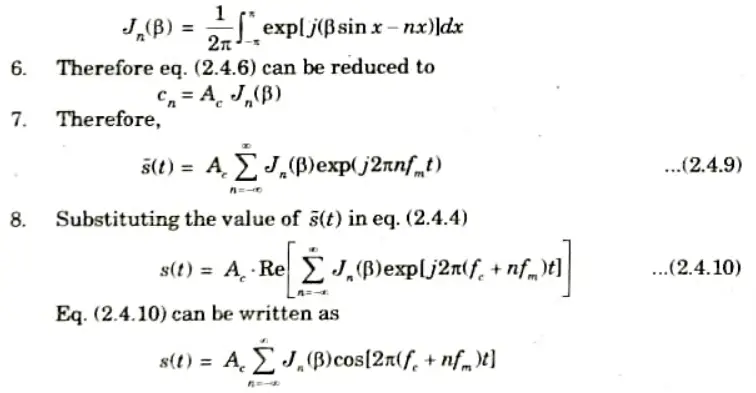
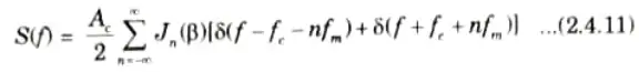
9 Thus, the discrete spectrum of s(t) is obtained by taking fourier transform of both the sides
c. Explain coherent method of generation and detection of PAM signal with suitable mathematical expressions.
Ans. A. Generation:
- 1. There are two operations involved in the generation of PAM signal:
- a. Instantaneous sampling of the message signal m(t) where the every Ts seconds, sampling rate fs = 1/Ts is chosen in accordance with the sampling theorem.
- b. Lengthening the duration of each sample so obtained to some constant value T.
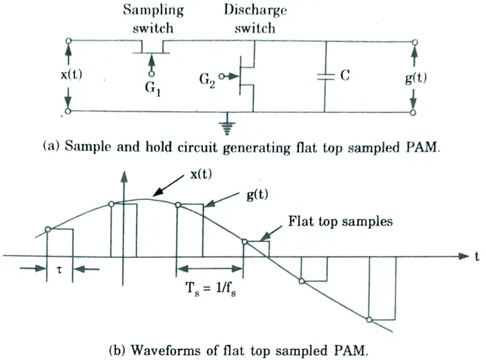
- 2. The sample and hold circuit consists of two field effect transistor switches and a capacitor.
- 3. The sampling switch is closed for a short duration by a short pulse applied to the gate G1 of the transistor. During this period, the capacitor C is quickly charged up to a voltage equal to the instantaneous sample value of the incoming signal.
- 4. Now, the sampling switch is opened and the capacitor holds the charge.
- 5. The discharge switch is then closed by a pulse applied to gate G2 of the other transistor. Due to this, the capacitor is discharged to zero volts. The discharges switch is then opened and thus capacitor has no voltage. Hence the output of the sample and hold circuit consists of a sequence of flat-top samples.
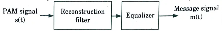
B. Detection:
- 1. The aperture effect describes the distortion brought on by the use of PAM to transmit an analogue information-bearing signal.
- 2. To remedy this distortion, connect an equalizer to the low-pass reconstruction filter in cascade as illustrated in Fig.
- 3. In order to account for the aperture impact, the equalizer has the effect of reducing the reconstruction filter’s in-band loss as frequency increases.
- 4. Ideally, the magnitude response of the equalizer is given by
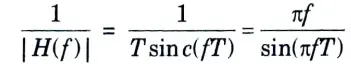
5. The amount of equalization needed in practice is usually small.
C. Mathematical representation:
1. We may express the PAM signal as
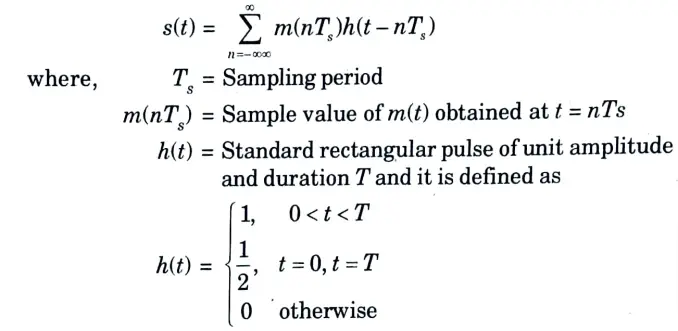
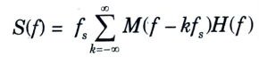
2. The spectrum of flat-top PAM signal is
d. Compare ASK, PSK and FSK. Also give the advantages and disadvantages of ASK, PSK and FSK.
Ans.
| S. No. | ASK | FSK | PSK |
| 1. | In this modulation method, the carrier signal’s amplitude is changed while its frequency and phase are held constant. | Here, the carrier signal’s frequency is changed but its amplitude and phase are held constant. | Here, the carrier signal’s frequency and amplitude are held constant while its phase changes. |
| 2. | This scheme is advantageous only in terms of simplicity and low implementation cost. | As the receiver is seeking for frequency shifts while using FSK rather than ASK, noise spikes can be disregarded. | PSK is extremely advantageous as it is less susceptible to errors han ASK. It is very robust in terms of noise tolerance. |
| 3. | ASK is commonly used to transmit digital data over optical fiber and is a very popular modulation used in control application. | FSK is popularly used in data transmission over voice lines, early modem and in high frequency radio transmission. | PSK is commonly used in signaling channels and in many systems like DTV, WLAN etc. |
| 4. | Only the presence or absence of a sinusoid in a specific time window needs to be identified for demodulation. | The demodulator must be able to identify which of the two potential frequencies is present at a specific moment in order to perform demodulation. | The phase of the received sinusoid relative to some reference phase must be ascertainable by the PSK demodulator. |
Advantages of ASK:
- 1. It is the simplest form of digital modulation scheme.
- 2. It is simple to design, easy to generate and detect.
- 3. It requires low bandwidth.
Disadvantages of ASK:
- 1. It is an inefficient digital modulation technique.
- 2. It is susceptible to sudden amplitude variations due to noise and interference.
Advantages of FSK:
- 1. It has better noise immunity than ASK.
- 2. The peak frequency offset is constant and always at its maximum value.
- 3. The highest fundamental frequency is equal to half the information bit rate.
- 4. The probability of error-free reception of data is quite high.
Disadvantages of FSK:
- 1. It is not very efficient in terms of transmission bandwidth requirement.
- 2. It has a poorer error performance than PSK or QAM.
Advantages of PSK: It is a more power-efficient modulation technique than the ASK and FSK.
Disadvantages of PSK:
- 1. Lower bandwidth efficiency.
- 2. These detection and recovery algorithms are very complex.
e. Explain Time Division Multiplexing (TDM) technique with suitable diagram.
Ans.
- 1. Time division multiplexing (TDM) allows a number of independent message sources to jointly use a single communication channel without interfering with one another.
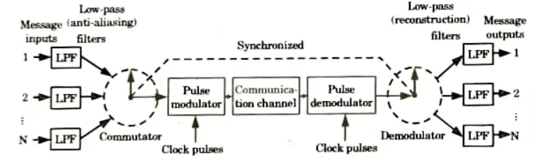
- 2. The concept of TDM is shown in Fig. Each input message signal is first restricted in bandwidth by a low-pass anti-aliasing filter to remove the frequençies that are non-essential to an adequate signal representation.
- 3. Commutator is usually implemented using electronic switching circuitry. Mainly two functions are done by commutator:
- a. To take a narrow sample of each of the N input messages at a rate fs that is slightly higher than 2W, where W is the cutoff frequency of the anti-aliasing filter.
- b. To sequentially interleave these N samples inside the sampling interval Ts.
- 4. The multiplexed signal is applied to a pulse modulator after passing via a commutator in order to be converted into a format that can be transmitted over the common channel.
- 5. The received signal is applied to a pulse demodulator at the system’s receiving end, which executes the pulse modulator’s opposite function.
- 6. The decommutator, which runs in sync with the transmitter’s commutator, distributes the narrow samples generated at the pulse demodulator output to the necessary low pass reconstruction filters. The successful execution of this synchronization is crucial.
- 7. The TDM system is extremely vulnerable to dispersion in the common channel, such as fluctuations in amplitude with frequency or a lack of proportionality in phase with frequency.
- 8. To ensure that the system operates satisfactorily, the channel’s magnitude and phase responses must be accurately equalized.
Section 3: Super Heterodyne Receiver Aktu Long Questions
a. Why super heterodyne receiver is better than the TRF receiver ? Explain.
Ans.
- 1. The super heterodyne receiver outperforms the TRF receiver because it is more sensitive and uniformly selective, has higher amplification, and is more selective.
- 2. In addition to these benefits, it features fewer variable-tuned circuits, making it easier to expand the receiver’s frequency band coverage.
- 3. For these reasons, super heterodyne have replaced TRF receivers for practically all uses.
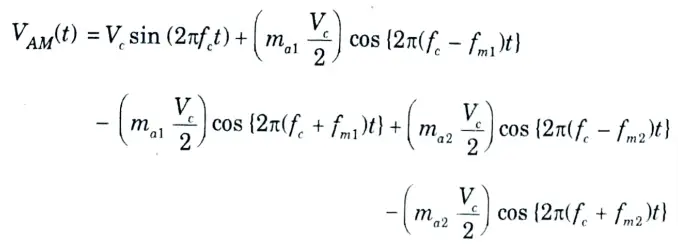
b. An arbitrary modulating signal consisting of two modulating frequencies of 1 kHz and 2 kHz modulated a carrier signal having peak amplitude level of 1 V and frequency of 1 MHz, with amplitude modulation index of 0.5 and 0.2 respectively. Write the resultant expression for complex AM signal and sketch its frequency spectrum.
Ans. 1. We know that the expression for complex AM signal for two modulating frequencies in frequency domain can be represented as
2. Using given frequency values as
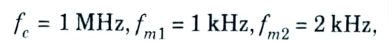
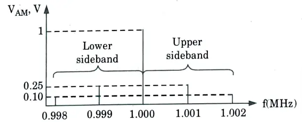
the frequencies of five frequency components in AM signal can be determined as
i. The carrier frequency,
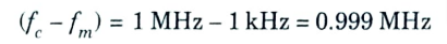
ii. The first lower-sideband frequency,
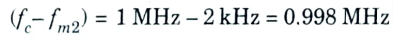
iii. The second lower-sideband frequency,
iv. The first upper-sideband frequency,

v. The second upper-sideband frequency,

3. Using given data for
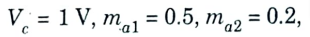
the peak amplitude levels of these five components can be determined as:
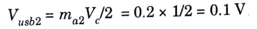
i. The peak amplitude of carrier signal,

ii. The peak amplitude of first lower sideband,
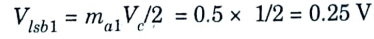
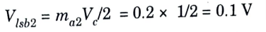
iii. The peak amplitude of second lower sideband,
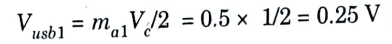
iv. The peak amplitude of first upper sideband,
v. The peak amplitude of second upper sideband,
4. Thus, the resultant expression for complex AM signal can be written as
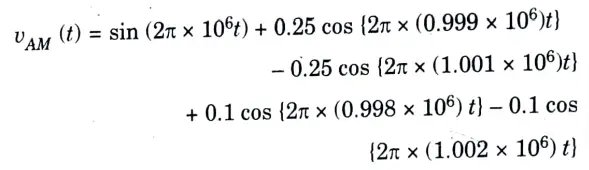
5. The frequency spectrum of the complex AM signal is shown in Fig.
Section 4: Forms of Noise Aktu Previous Repeated Questions
a. What is noise ? Explain various forms of noise and its sources.
Ans. A. Noise:
- 1. Any energy that is introduced unintentionally and has the potential to interfere with the accurate receipt and replication of sent signals is considered noise.
- 2. Another way to think of noise is as an unwanted signal that tends to interfere with the communication system’s ability to transmit and process information signals.
- 3. Noise mostly interferes with the channel’s ability to transmit signals.
- 4. The message in the channel is added to almost all noise components.
- 5. The source of noise may be internal or external
B. Forms of noise and its sources :
External noise: The noise that is originated outside the receiver is known as external noise.
Atmospheric noise:
- 1. False radio signals with parts scattered across a wide frequency range make up atmospheric noise.
- 2. Static from both nearby and far-off thunderstorms can be picked up at any place on the ground because it travels over the earth in the same manner as regular radio signals of the same frequencies.
- 3. If the storm is local, the static is likely to be more intense but less frequent.
- 4. Because field strength is inversely related to frequency, this noise will disrupt television reception more so than radio.
- 5. Above 30 MHz, the severity of atmospheric noise decreases.
Extraterrestrial noise:
- 1. Extraterrestrial noise or space noise is observable at a frequency in the range from about 8 MHz to somewhat above 1.43 GHz.
- 2. This noise can be classified under two categories:
- a. Solar noise:
- 1. The frequencies that we utilise for communication are part of a very wide frequency band that the sun broadcasts over.
- 2. The sun is a star that is continually changing and going through periods of peak activity, from which electrical disturbances like corona flares and sunspots emerge.
- b. Cosmic noise:
- 1. Distant stars generate RP noise similarly to our sun since they are also suns and have extremely high temperatures.
- 2. Due to their distance from the earth, a number of disturbances build up and interfere with the communications system.
- c. Industrial noise:
- 1. The intensity of noise produced by humans between 1 and 600 GHz easily surpasses that of all other sources.
- 2. This topic covers a variety of sources, including leakage from high-voltage lines, electrical machinery, electric motors, and switching equipment.
- Internal noise:
- 1. Noise created by any of the active or passive devices found in receivers is known as internal noise.
- 2. This type of noise is also known as fluctuation noise.
The important types of internal noise are:
a. Thermal agitation noise:
- 1. Johnson noise, white noise, or thermal agitation are all terms for the random noise produced by a resistive component or resistance.
- 2. It results from the molecules inside the component itself moving quickly and randomly.
- 3. Because the kinetic energy and subsequently the particle velocity inside of a substance are proportional to its absolute temperature.
- 4. As a result, in addition to being proportional to the measurement bandwidth, the noise produced by a resistor is also proportional to its absolute temperature. Therefore
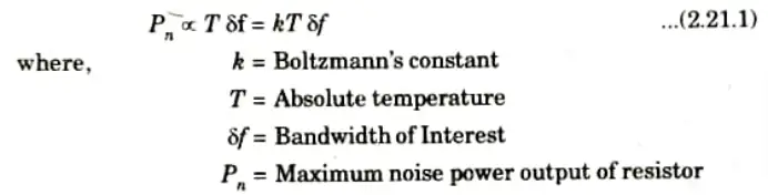
- 5. It must be realized that all formulas referring to random noise are applicable only to rms value of such noise; not to its instantaneous value, which is quite unpredictable.

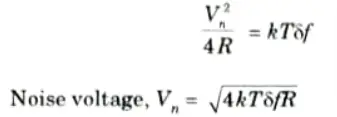
6. Hence from Fig.
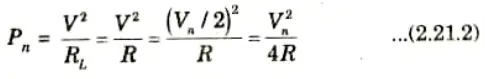
From eq. (2.21.1) and (2.21.2),
b. Shot noise:
- 1. The shot effect, which results in shot noise in all amplifying equipment and active devices, is the most significant of all the other sources.
- 2. It manifests as a randomly fluctuating noise current superimposed on the output and is created by random changes in the arrival of electrons at the output electrode of an amplifying device.
- 3. It should sound magnified like a shower of lead shot landing on a metal sheet. Hence, the term “shot noise” is used.
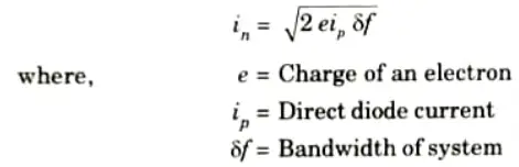
- 4. For a diode, the rms shot noise current is
c. Transit-time noise:
- 1. The so-called transit time effect occurs at frequencies in the upper VHIF range and above, increasing the transistor’s noise input admittance, if the time it takes an electron to move from the emitter to the collector of the transistor becomes significant to the period of the signal being amplified.
- 2. At such frequencies, the tiny currents created in the device’s input by random variations in the output current take on a significant role and produce random noise.
b. An FM modulator operates at carrier-signal frequency of 500 kHz having peak amplitude of 10 V. A modulating frequency (fm) of 10 kHz modulates it with a peak frequency deviation (𝛅) of 10 kHz. From the Bessel function table, it is observed that a frequency modulation index of one yield three sets of significant sidebands. Compare actual minimum bandwidth as obtained using Bessel function and the approximate minimum bandwidth using Carson’s rule.
Ans. Given: fm = 10 kHz, 𝛅 = 10 kHz, n = 3
To Find: Compare actual minimum bandwidth using Bessel function and the approximate minimum bandwidth using Carson’s rule.
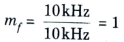
1. We know that frequency modulation index,

2. Using Bessel function, we know that actual minimum bandwidth,
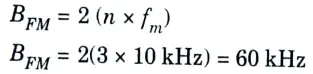
3. Using Carson’s rule, we know that approximate minimum bandwidth,
4. From the above results, it can be seen that
i. The minimal bandwidth calculated using the Bessel function and the minimum bandwidth calculated using Carson’s approach differ significantly.
ii. The estimated bandwidth derived from Carson’s rule is smaller than the actual minimum bandwidth needed to traverse the designated three important sidebands.
iii. Therefore, an FM system having mf < 5 would have a narrower bandwidth and thus, poorer performance, if it is Carson’s designed using rule.
Section 5: Delta Modulation Quantum Notes Pdf
a. Explain the working of delta modulation. How adaptive delta modulation improves the performance of delta modulation ?
Ans. A. Delta modulation:
- 1. Delta modulation (DM) is a DPCM scheme in which the difference signal 𝚫(t) is encoded into just a single bit.
- 2. The single bit is used to increase or decrease the estimate ḿ(t).
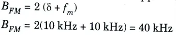
- 3. This scheme is called linear delta modulation and is shown in Fig.
- 4 The baseband signal mt) and its quantized approximation ḿ(t) are applied as inputs to a comparator.
- 5. A comparator makes a comparison between inputs.
- 6. The comparator has one fixed output V(H) when m(t) > ḿ(t) and different output V(L) when m(t) < ḿ(t).
- 7. The up-down counter increments or decrements its count by 1 at each active edge of the clock waveform.
- 8. The count direction, i.e., incrementing or decrementing, is determined by the voltage levels at the “count direction command” input to the counter.
- 9. When this binary input, which is also the transmitted output s0(t), is at the level VH), the counter counts-up and when it is at the level V(L) the counter counts down.
- 10. The digital output of the counter is converted to the analog quantized approximation ḿ(t) by the D/A converter.
- 11. The waveforms of Fig. are the waveforms for the system of Fig. assuming that the active clock edge is the falling edge.
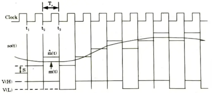
- 12. For a time preceding t1 we find m(t) > ḿ(t) so that s0(t) = V(H).
- 13. At t1, when the active clock edge appears, the counter is incremented and immediately signal ḿ(t) jumps up by an amount equal to the step size S.
- 14. At t2 we still find m(t) > ḿ(t), so s0(t) remains at V(H) and there is another upward jump in ḿ(t). At t3, m(t) < ḿ(t), so s0(t) becomes s0(t) = V(L), the counter decrements, and there is a consequent downward jump in ḿ(t) by amount S and so on.
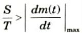
- 15. The excessive disparity between m(t) and ḿ(t) is described as a slope overload error and occurs whenever m(t) has a slope larger than the slope S/Ts which can be sustained by the waveform ḿ(t).
- 16. Slope overload can be avoided if
- 17. The dynamic range of amplitude of m(t) is too small because of the threshold and overload effects.
B. Adaptive delta modulation:
- 1. A delta modulation which adjusts its step size to overcome the drawback of slope overload distortion and granular noise is called adaptive delta modulation (ADM). It adopts itself to the changing signal conditions.
- 2. The block diagram of ADM is shown in Fig. Slope-overload can be overcome if the step size is increased in such a way that the magnitude of the slope of m(bar)(t) becomes greater than the magnitude of the slope of m(t), and when the signal variations are less than the step size, the step size may be reduced to take care of the situation.
- 3. On the transmitter side, a variable gain amplifier is used before the integrator with P0(t) as its input.
- 4. The gain of this amplifier depends on the gain control input, which is obtained by integrating P0(t) in an RC-network, and then passing the integrator output through a square law device.
- 5. Under the slope-overload condition, P0(t) is a long sequence of either positive or negative pulses. The RC integrator integrates these pulses. Thus, the output of this integrator is either of a large positive or negative value.
- 6. The square law device output is of a large positive value, irrespective of whether the input is positive, or negative. Thus, the gain control input of the variable gain amplifier is large and its gain increases. Hence the step size increases, which can then take care of the slope-overload.
- 7. When the signal variations are within the step size, P0(t) is a sequence of alternate positive and negative pulses. The RC integrator output in this case is zero and, hence, the gain control input of the variable gain amplifier is also zero.
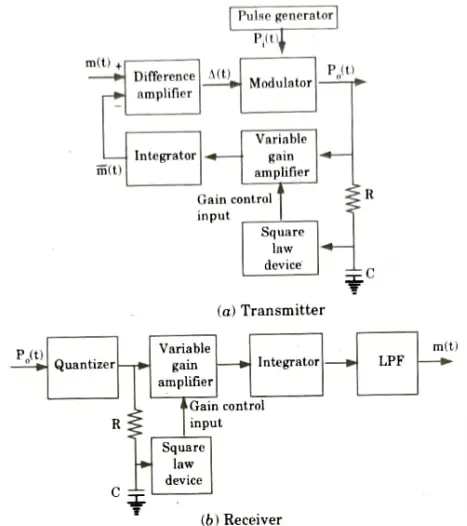
- 8. The gain of the variable gain amplifier decreases, resulting in a reduced step size, which takes care of the situation.
- 9. On the receiver side, the output of the quantizer is fed to a variable gain amplifier whose gain control input is derived from an RC integrator and a square law device. Thus, an adaptive adjustment of the step size is obtained at the receiver, resulting in an undistorted of the transmitted signal.
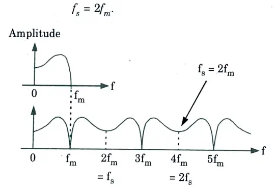
b. Let the maximum spectral frequency component (fm) in an analog information signal is 3.3 kHz. Illustrate the frequency spectra of sampled signals under the following relationships between the sample frequency, fs and maximum analog signal frequency, fm–
i. fs – 2fm
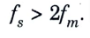
ii. fs > 2fm
Ans. i. For given value of
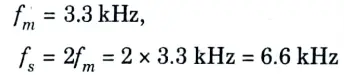
Fig. illustrates the frequency spectra of sampled signals for

i. For given value of
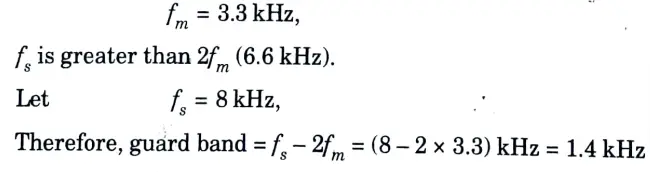
Fig. illustrates the frequency spectra of sampled signals for
Section 6: Pulse Code Modulation (PCM) Aktu Important Notes Pdf
a. What is pulse code modulation (PCM) ? Explain briefly, generation and detection of PCM.
Ans. PCM (pulse code modulation):
- 1. A communication signal is represented by a series of coded pulses in pulse code modulation (PCM), which is accomplished by encoding the signal in discrete form in both time and amplitude.
- 2. As depicted in Fig., sampling, quantization, and encoding are the three primary PCM operations. A continuous time signal is sampled during the sampling process by measuring its amplitude at a discrete instant.

- 3. Representing the sampled values of the amplitude by a finite set of levels is called quantizing.
- 4 Designating each quantized level by a code is called encoding.
PCM transmitter (Encoder):
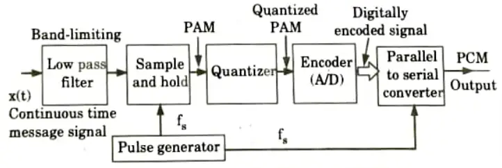
Operation:
- 1. The analog signal x(t) is passed through a band limiting low pass filter, which has a cut-off frequency fc = W Hz. This will ensure that x(t) will not have any frequency component higher than W. This will eliminate the possibility of aliasing.
- 2. After that, a sample and hold circuit receives the band-limited analogue signal and samples it at a rate that is sufficiently high. It produces a flat-topped PAM signal as its output.
- 3. The quantizer then performs the quantization procedure on these samples. The technique of approximation is known as quantization. The impact of noise is lessened by quantization. The quantized PAM is created at the quantizer output by the combined effects of sampling and quantization.
- 4. The quantized PAM pulses are applied to an encoder which is basically an A to D converter. Each quantized level is converted into an N-bit digital word by the A to D converter. The value of N can be 8, 16, 32, 64 etc.
- 5. The encoder output is converted into a stream of pulses by the parallel to serial converter block. Thus at the PCM transmitter output we get a train of digital pulses.
- 6. A pulse generator produces a train of rectangular pulses with each pulse of duration 𝝉 seconds. The frequency of this signal is fs Hz. This signal acts as sampling signal for the sample and hold block. The same signal acts as clock signal for the parallel to serial converter. The frequency fs is adjusted to satisfy the Nyquist criteria.
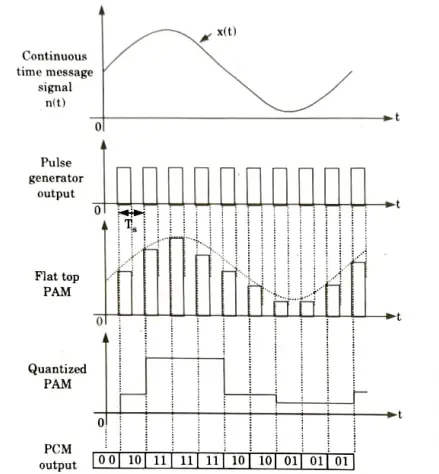
Waveforms: The waveforms at various points in the PCM transmitter are as shown in Fig.
PCM Receiver (Decoder):
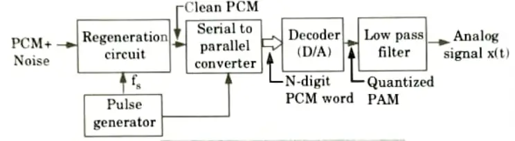
- 1. The receiver input is able to receive a PCM signal that has been tainted with noise.
- 2. The receiver’s regeneration circuit will deconstruct the original PCM signal and extract the PCM pulses from noise.
- 3. The pulse generator’s operation must be synchronised with the transmitter’s. As a result, a pure PCM signal is output from the regeneration circuit.
- 4. A serial to parallel converter is next used to convert the PCM signal, and the output of this block is then applied to a decoder.
- 5. The decoder, a D to A converter, does the exact opposite of what the encoder does.
- 6. The sequence of quantized multilayer pulses is the decoder output. Hence, the decoder’s output contains the quantized PAM signal.
- 7. To retrieve the analogue signal, x, the quantized PAM signal is routed through a low pass filter (t).
- 8. The reconstruction filter’s cut-off frequency is equal to the message bandwidth W, and it is referred to as a low pass filter.
b. A discrete memoryless source X has five symbols (s0, s1, s2, s3, s4) and their probabilities of occurrence are given as 0.40, 0.20, 0.20, 0.10, 0.10, respectively. Construct Huffman code and calculate efficiency.
Ans.
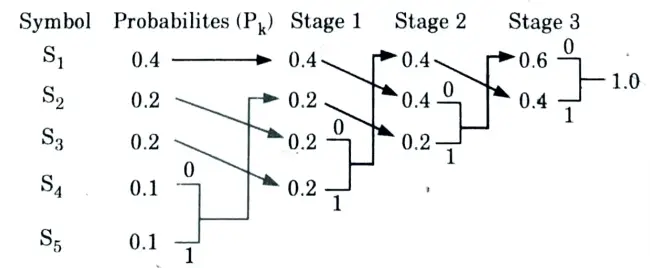
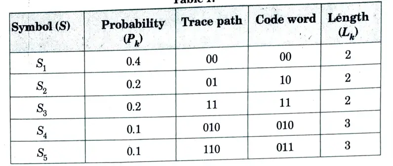
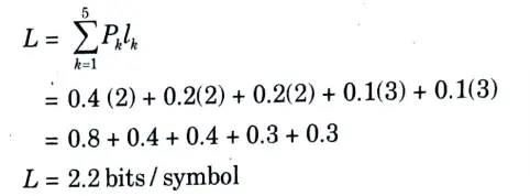
1. Average code word length (L)
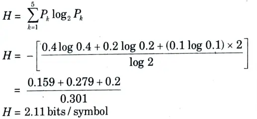
2. Entropy (H),

Section 7: T-1 Carrier System Long Important Questions with Answer
a. Explain T-1 carrier system with the help of block diagram.
Ans.
- 1. In PCM, time division multiplexing is possible. In this, each sample is coded into several bits.
- 2. The multiplexing is possible in two ways:
- i. Bits are extracted one by one from the sample code for each channel. The commutator gets the second bits from all channel samples after taking the first bits from all channel samples, and so on.
- ii. The entire first channel sample’s code bits are captured, then the entire second channel sample’s code bits, and so on. The commutator speed that is wanted in this method is lower than the one that is necessary in the first.
- 3. Each frame has a synchronizing bit inserted at the end to keep the commutator and decommutator in sync. The name “synchronous time division multiplexing” comes from the fact that the signal being time division multiplexed is band restricted to the same frequency, resulting in the same sampling frequency for all of the channels.
T1 digital system (T1 system) or T1 carrier system:
- 1. T1 digital system is used to convey multiple signals over telephone lines using wideband co-axial cable.
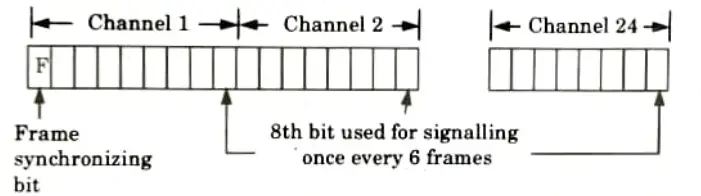
- 2 It accommodates 24 analog signals which refer as S1 through S24.
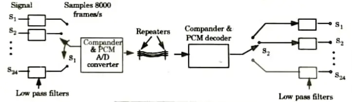
- 3. Each signal is band restricted to about 3.3 kHz and sampled at a rate of 8 kilobits per second. Each time division multiplexed signal (which is still analogue) is then transformed and combined using an A/D converter.
- 4. The resulting digital waveform is then transferred across a coaxial connection, which reduces signal jitter and suppresses signal corruption brought on by outside noise.
- 5. The duplicate of the original signal that was sent, without any distortion or noise, is retransmitted by the repeater.
- 6. The signal is combined, decoded, and demultiplexed at the destination, releasing each of the 24 original signals.
Bits/frame:
- 1. The commutator sweeps continuously from S1 to S24 and back to S1 etc., at the rate of 8000 revolutions per second thereby providing 8000 samples per second of each signal.
- 2. Each sample is encoded into eight bits (corresponding to 28 = 256 quantization levels).
- 3. The digital signal generated during the course of one complete sweep of the commutator is therefore 24 x 8 = 192 bits.
Frame synchronization:
- 1. A single extra bit is made available before the 192 bits that convey the encoded signals in order to achieve synchronisation.
- 2. A frame is defined as the 193 bits, or the 192 bit slots allotted to the encoded signal plus the additional time bit.
- 3. The time slots for the 24 signals together with the extra frame synchronizing bit F is shown in Fig.
Bit rate:
1. Each signal is sampled 8000 times per second so that a complete frame occupies a time
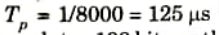
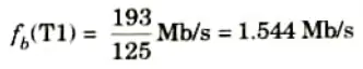
2. This time Tp accommodates 193 bits so that the bit rate on a T1 channel is
Signaling: The frequency of the bits used for signaling is 1/6th of the frame bít rate, or
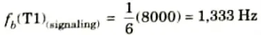
This type of signaling is called channel-associated signaling.
b. Consider 8 different alphabet source with probability of occurrence are given in Table 2:
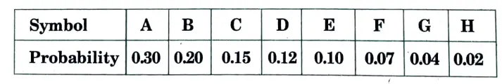
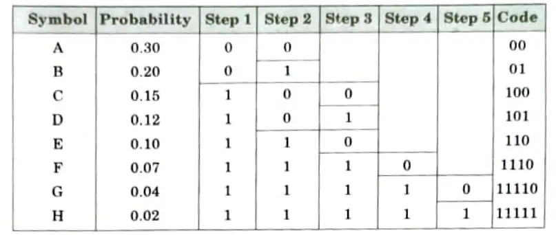
According to Shannon-Fano technique generates binary code and calculates average word length, Entropy, and efficiency.
Ans. A. Binary codes:
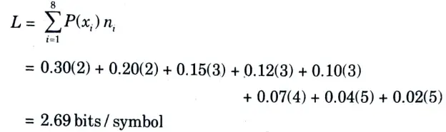
B. Average word length:
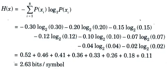
C. Entropy:
D. Efficiency:
6 thoughts on “Analog and Digital Communication: Aktu Previous Solved Question Paper Quantum Notes”