
Aktu’s Quantum Notes and Master Control Systems. To succeed in your B.Tech courses, access key information and frequently asked questions. Your road to success begins right here! Unit-5 Introduction to Design
Dudes 🤔.. You want more useful details regarding this subject. Please keep in mind this as well.

Important Questions For Control System:
*Quantum               *B.tech-Syllabus
*Circulars                *B.tech AKTU RESULT
* Btech 3rd Year    * Aktu Solved Question Paper
Q1. Explain the lag compensation.
Ans. 1. In phase lag compensating network, the phase of output voltage lags the phase of input voltage for sinusoidal inputs. It is a simple and commonly used network.
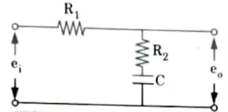
2. The transfer function of phase-lag network is shown in Fig.
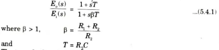
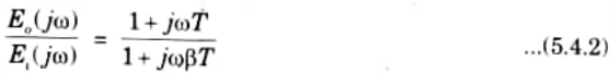
3. The transfer function given by eq. (5.4.1) can be expressed in sinusoidal form as
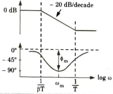
4. Bode plot for transfer function of eq. (5.4.2) is shown in Fig. 5.4.2.
Q2. Explain Bode plot method to design a lag compensator.
Ans. A. Design procedure of lag compensator:
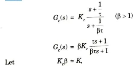
Step 1: Let the system transfer function of controller be
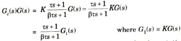
The OLTF of the compensated system is
Now, determine gain K to satisfy the requirement on the given static velocity error constant.
Step 2: Using the value of K determined in step 1, draw Bode plot of G1(jω). Find the phase margin (ф).
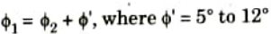
Step 3: Using specified phase margin (ф), find the required phase margin ф1
Step 4: Find the frequency at which the phase angle of the open loop transfer function is equal to – 180° plus the required margin (ф1). This is the new gain crossover frequency.
Step 5: Determine attenuation necessary to bring the magnitude curve down to 0 dB at the new gain crossover frequency. This change is due to the factor (ß) and the attenuation is – 20 log ß. For this shift find the value of ß.
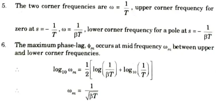
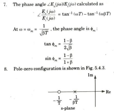
Step 6: Determine the other corner frequency (corresponding to pole of lag compensator) from
Step 7: Using the value of K determined in step 1 and ß determined in step 5, calculate constant Kc as

Step 8: Using the transfer function of lag compensator, draw Bode plot and verify specifications.
B. Effects of lag compensation: It has a high gain at low frequencies, hence it is essentially a low pass filter. As a result, it increases steady-state performance.
Q3. Explain lead-lag compensator. Also write the effects of lead-lag compensation ?
Ans. A. Lead-lag compensator:
1. Lead-lag compensator is combination of lead network and lag network.
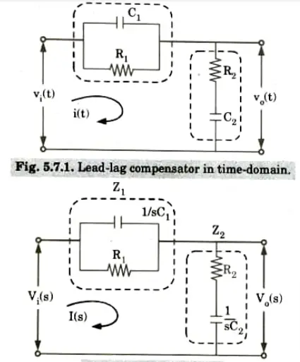
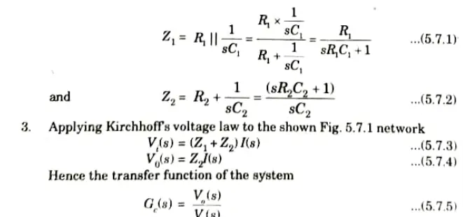
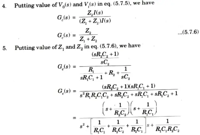
2. From Fig. 5.7.2, we have
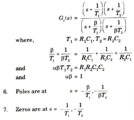
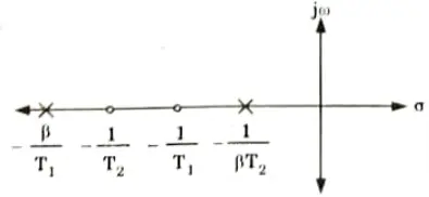
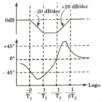
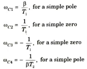
8. The various corner frequencies of the lag-lead compensator are,
B. Effects:
- 1. The lag-lead compensator enhances the steady state by increasing the low frequency gain.
- 2. It boosts the system’s bandwidth, allowing it to respond quickly.
Q4. Write down the procedure for designing lag-lead compensator.
Ans.
- 1 Assess the uncompensated system’s performance to determine how much improvement in transient responsiveness is required.
- 2. Create the lead compensator to suit the transient response requirements. The loop gain, zero location, and pole location are all part of the design.
- 3. Run the system simulation to ensure that all requirements have been met.
- 4 Redesign if the simulation reveals that the requirements were not met.
- 5. Assess the steady-state error performance of the lead-compensated system to decide how much more steady-state error improvement is required.
- 6. Create the lag compensator so that it produces the desired steady-state error.
- 7. Run the system simulation to ensure that all requirements have been met.
- 8. Redesign if the simulation reveals that the requirements were not met.
Q5. Define the following terms:
i. State
ii. State variables
iii. State vector
iv. State space
v. State equation
Ans. i. State: The state of a dynamic system is the smallest set of variables such that the knowledge of these variables at t = t0 with the knowledge of the input for t ≥ t0 completely determines the behaviour of the system for any time t ≥ t0.
ii. State variables: The variables involved in determining the state of dynamics system are called state variables.
iii. State vector: If we need n variable to completely describe the behaviour of a given system, then these n state variables may be considered as n component of a vector x. Such a vector is called state vector
iv. State space: The n-dimensional space whose coordinate axis consists of the x1 axis, x2 axis.., xn axis is called state space. Any state can be represented by a point in the state space.
v. State equation: A state space representation is a mathematical model of the physical system as a set of output, input and state variables related by a differential equation is known as state equation.
Advantages of state space techniques:
- 1. The method considers the impact of all initial conditions.
- 2 It is applicable to both non-linear and time-varying circumstances.
- 3. It is easily applicable to multiple input multiple output systems.
- 4. With this current technology, the system can be exactly constructed for optimal conditions.
Q6. Explain the correlation between transfer function and state space equations.
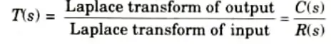
Ans. A. Transfer Function : On the premise that all initial conditions are zero, the transfer function is defined as the ratio of the system’s Laplace transform’s output to input.
B. Derivation:
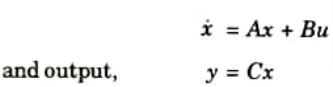
1. Let us consider a vector matrix differential equation
2. Now, taking Laplace transform with zero initial conditions
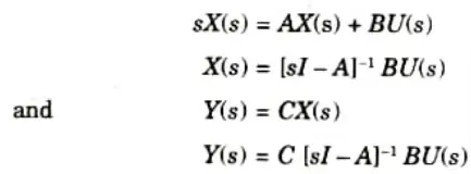
3. For a single-input-single-out put system, Y and U are scalars.
4. Now transfer matrix can be given as
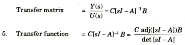
6 Denominator part i.e,. |sI – A| is called the characteristic equation.
|sI – A| = 0
7. nth degree characteristic equation |sI – A| = 0 has n roots or eigen values.

Control System Btech Quantum PDF, Syllabus, Important Questions
| Label | Link |
|---|---|
| Subject Syllabus | Syllabus |
| Short Questions | Short-question |
| Question paper – 2021-22 | 2021-22 |
Control System Quantum PDF | AKTU Quantum PDF:
| Quantum Series | Links |
| Quantum -2022-23 | 2022-23 |
AKTU Important Links | Btech Syllabus
| Link Name | Links |
|---|---|
| Btech AKTU Circulars | Links |
| Btech AKTU Syllabus | Links |
| Btech AKTU Student Dashboard | Student Dashboard |
| AKTU RESULT (One VIew) | Student Result |