
With Aktu Quantum Notes, you can discover the secrets to B.Tech success. These simple yet thorough notes concentrate on the most important and often asked questions in Analogue and Digital Communication. Master your examinations right now! Unit-3 Pulse Modulation
Dudes 🤔.. You want more useful details regarding this subject. Please keep in mind this as well.

Important Questions For Analog and Digital Communication:
*Quantum               *B.tech-Syllabus
*Circulars                *B.tech AKTU RESULT
* Btech 3rd Year    * Aktu Solved Question Paper
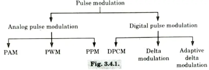
Q1. What is pulse modulation and what are their different types ? Also give advantage of pulse modulation.
Ans. 1. In pulse modulation, the carrier consists of a pulse train, some parameters of which are varied in accordance with the instantaneous value of the modulating signal. Pulse modulation can be classified as follows :
2. The primary distinction between pulse analogue and pulse digital modulation is that the former transmits information in the form of pulses, while the latter transmits it as digital data that has been encoded.
Types of analog pulse modulation:
- 1. Pulse Amplitude Modulation (PAM): In this type of pulse modulation, the height of the pulse is made proportional to the sampled value.
- 2. Pulse Duration or Width Modulation (PDM or PWM): In this type of pulse modulation, width of the pulse is varied as a function of the sampled value.
- 3. Pulse Position Modulation (PPM): In this type of pulse modulation, the position of pulse is changed as a function of the sampled value.
Advantage of pulse modulation :
- 1. Rather than being given constantly, the transmitted power can be condensed into brief bursts.
- 2. Sample values from other messages can be used to fill the time gaps between pulses, enabling the transmission of many messages through a communication channel.
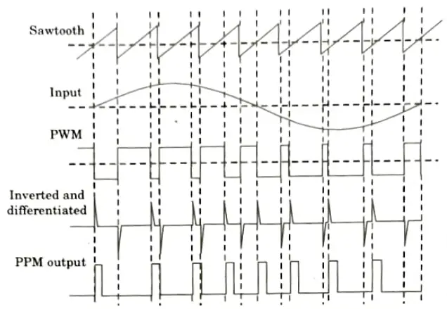
Q2. Draw the block diagram of generation of PWM and explain the working operation.
Ans. A. Generation of PWM and PPM:
- 1. The message signal modulates the position of the arrival of a fixed width pulse during each sample period in pulse position modulation as well as the width of the pulse in pulse width modulation.
- 2. PWM and PPM are not suited for time division multiplexing schemes because to the randomness of their width and position, respectively, hence their contribution to communication is minimal.
- 3. In the simplest way, we have a comparator, whose inputs are fed by a sawtooth signal that operates at carrier frequency and a message input signal.
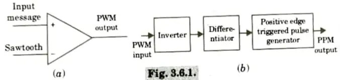
- 4. The input signal’s maximum should be lower than the sawtooth signal’s maximum. Get a PWM signal at the comparator’s output if that is the case.
- 5. PWM pulses happen at regular intervals, and their rising edge coincides with the sawtooth signal’s falling edge.
- 6. This is due to the fact that the +ve input of the comparator is at a higher potential and the comparator output will be -ve when the sawtooth signal is at its minimum, which is always smaller than the minimum of the input signal.
- 7. PPM generation is usually a post processing of PWM signal.
- 8. An inverter that reverses the polarity of the pulses receives the PWM signal that was generated. If a differentiator is used after it, it will produce +ve spikes where the original PWM signal pulse went from high to low and -ve spikes where it went from low to high.
- 9. After being supplied to a +ve edge triggered fixed width pulse generator, which produces pulses of a defined width whenever a +ve spike arises and coincides with the falling edge of the original PWM signal, these spikes are then fed.
B. Demodulation of PWM and PPM:
- 1. We want to start a ramp for PWM demodulation at the positive edge and terminate it when the negative edge appears.
- 2. Because the ramps’ widths vary, they will rise to varying heights in relation to the modulating message’s amplitude, which is directly proportional to the pulse width.
- 3. This will follow the envelope when put through a low pass filter, i.e., the message signal, and the demodulation is complete.
- 4. In PPM demodulation, the ramp begins at one pulse’s positive edge and ends at the pulse’s subsequent positive edge.
- 5. As a result, the amplitude of the modulating message closely follows the delay between the pulses, which in turn determines the height of the ramp that is formed.
- 6. A low pass filter eliminates the demodulated signal that contains envelope information.
- 7. A demodulator circuit can be built using transistor and RC combinations for ramp production and filtering.
Q3. What is line coding? Explain its various types.
Ans. A. Line coding: Line coding is the process of encoding digital data into a digital signal.
B. Different line codes are:
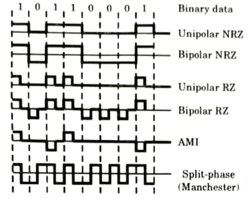
- a. Unipolar non-return to zero (NRZ) signaling:
- 1. Symbol 0 is represented by no pulse, while symbol 1 is represented by sending a pulse with a consistent amplitude over the whole bit interval.
- 2. NRZ means that the designated amplitude level is held constant for the duration of the bit interval.
- b. Bipolar NRZ signaling : Equally sized positive and negative pulses are used to represent the numbers 1 and 0. In this instance, the bit interval’s allocated pulse amplitude level is preserved.
- c. Unipolar return to zero (RZ) signaling: A positive pulse that drops to zero before the conclusion of the bit interval is symbolic of symbol 1, and the absence of a pulse is symbolic of symbol 0.
- d. Bipolar RZ signaling: Positive and negative pulses of equal amplitude are used for symbols 1 and 0, respectively. In either case the pulse return to 0 before the end of bit interval.
- e. Alternate mark inversion (AMI) RZ signaling: With symbol 1, alternate positive and negative pulses are employed, but for symbol 0, there is no pulse at all. In either scenario, the pulse returns to zero before to the bit interval’s conclusion.
- f. Split-phase (Manchester) signaling: For symbol 0, these pulses’ polarity are reversed, whereas for symbol 1, they have equal amplitudes and half-bit durations. Symbol 1 is represented by a positive pulse followed by a negative pulse.
Q4. Differentiate between the delta modulation technique and adaptive delta modulation technique. Explain the importance of companding technique.
Ans. A. Difference:
| S. No. | Data Modulation (DM) | Adaptive Delta Modulation (ADM) |
| 1. | It uses only one bit for one sample. | Only one bit is used to encode one sample. |
| 2. | Step size is fixed and cannot be varied. | According to the signal variation, step size varies (adapted). |
| 3. | Slope overload distortion and granular noise is present. | Quantization error is present but other errors are absent. |
B. Importance of companding :
- 1. Companding is a non-uniform quantization. It is required to be implemented to improve the signal to quantization noise ratio of weak signals.
- 2. The quantization error depends upon the step size.

this shows that in the uniform quantization once the step size is fixed, the quantization noise power remains constant.
- 3. Nevertheless, the signal power fluctuates. It has a square relationship to the signal amplitude. As a result, signal strength will be low for weak signals while quantization noise strength remains constant.
- 4. As a result, the weak signals have very low signal to quantization noise ratios.
- 5. As a result, before applying signals to a uniform quantizer, weak signals are amplified and strong signals are muted.
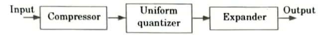
- 6. This procedure is known as compression, and the building piece that makes it possible is known as a compressor.
- 7. At the receiver, the expansion procedure is carried out exactly the opposite way. A circuit called an expander is used to provide expansion.
- 8. The compression of signal at the transmitter and expansion at the receiver is combined to be called as companding.
- 9. The process of companding is shown in the block diagram form in Fig.
Advantages of companding:
- i. Companding is done to avoid non-linear distortion of channel.
- ii. It is used to restore the signal samples to their corrective level.
Q5. Discuss the role of equalizer. Also explain the role of normalized equalization.
Ans. Equalizer:
- 1. An equalizer is a device that tries to undo the distortion that a signal experiences while being delivered across a channel.
- 2. Its goal in digital transmission is to lessen inter-symbol interference so that the transmit symbols can be recovered.
- 3. It could be an intricate algorithm or a straightforward linear filter.
Role of equalizer:
- 1. The intersymbol interference causes distortion. These distortions can be reduced by designing a proper equalizer.
- 2. If the frequency response of the channel Hc(ω) 1s completely known, then, an equalizer is designed whose frequency response He(ω) is the inverse of Hc(ω).
- 3. Equalizing filters are inserted between the receiving filter and the A/D converter.
Role of normalized equalization: It is use to compensate for aperture effect.
Q6. The spectral range of a bandpass signal extends from 10.0 MHz to 10.04 MHz. Find the minimum sampling rate.
Ans. 1. Bandwidth = 10.04 MHz -10 MHz
= 0.04 MHz
2. Then, minimum sampling rate can be given as
Minimum sampling rate = 2 x Bandwidth
= 2 x 0.04
= 0.08 MHz

Analog and Digital Communication Btech Quantum PDF, Syllabus, Important Questions
| Label | Link |
|---|---|
| Subject Syllabus | Syllabus |
| Short Questions | Short-question |
| Question paper – 2021-22 | 2021-22 |
Analog and Digital Communication Quantum PDF | AKTU Quantum PDF:
| Quantum Series | Links |
| Quantum -2022-23 | 2022-23 |
AKTU Important Links | Btech Syllabus
| Link Name | Links |
|---|---|
| Btech AKTU Circulars | Links |
| Btech AKTU Syllabus | Links |
| Btech AKTU Student Dashboard | Student Dashboard |
| AKTU RESULT (One VIew) | Student Result |