
Table Of Contents
Improve your B.Tech experience with quantum notes that include important and often asked Aktu questions on advanced welding. Explore this resource in-depth for thorough understanding and exam achievement. Unit-5 Weld Design and Welding Codes
Dudes 🤔.. You want more useful details regarding this subject. Please keep in mind this as well.

Important Questions For Advance Welding:
*Quantum                *B.tech-Syllabus
*Circulars                 *B.tech AKTU RESULT
* Btech 3rd Year     * Aktu Solved Question Paper
Q1. Explain the welding symbol with an example.
Ans. A. Welding Symbols:
- 1. Welding symbols offer a way to include information on the kind, size, location, etc. of the welds in welded joints on drawings.
- 2. Fig. provides the fundamental symbols that can be used to depict the many types of welds.
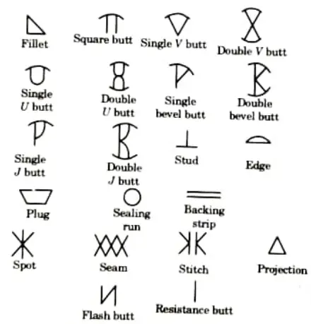
B. Different Welding Symbols:
- i. Fillet Welds:
- 1. Fillet weld symbol is used to make lap joints, corner joints, and T-joints.
- 2. The filet weld is roughly triangular in cross-section.
- ii. Groove or Butt Welds:
- 1. The geometry of the components to be joined and the preparation of their edges have a major impact on the type of butt weld symbol that is used.
- 2. Some butt weld symbols are V-butt, square butt, U-butt, Bevel butt, J-butt etc.
- iii. Plug Welds:
- 1. To attach the overlapping pieces, one of which has holes in it, plug weld symbols are utilized.
- 2. The depth to which the hole is to be filled with weld metal, if it is not to be totally filled, is indicated within the weld symbol.
- 3. Plug welds are commonly used with other welds in the rails.
- iv. Stud Welds:
- 1. The electric arc procedure that quickly welds a fastener to a base metal or substrate uses the stud weld symbol.
- 2. It is a quick, dependable, and precise way of joining two metal objects together with a fastener.
- v. Slot Welds:
- 1. Plug welds do not have a length component, however slot weld symbols provide information similar to that of plug weld symbols.
- 2. The diameter of a plug weld determines its size, whereas the width of a slot does.
- vi. Seam Welds:
- 1. A lap joint that may be made up of two or more lapped sections is indicated by the symbol for a seam weld. This type of weld occurs between the faying surfaces of the lap joint.
- 2. It is used in resistance welding.
- vii. Edge Welds:
- 1. This symbol is used when two sheets or plates’ edges are close together and almost parallel to one another at the welding joint.
- viii. Projection Welds:
- 1. This symbol is used in the process of projection welding.
- 2. Projection welds must be dimensioned by strength.
- ix. Backing Strip Welds:
- 1. The symbol is used to signify the welding of tanks.
- 2. It is deployed for root runs with single V as well as double V configurations.
- x. Spot Welds:
- 1. The resistance spot welding industry uses the symbol exclusively.
- 2. The method dampens the sheets together while concentrating welding current into a limited area using two shaped copper alloy electrodes.
Q2. Explain how a good joint design can be selected ?
Ans. For selection of good joint design weldment should have following considerations:
- 1. Appropriately made to provide the specified service for the necessary time.
- 2. Made in accordance with the design concepts and using the required materials.
- 3. Well handled and maintained.
- 4. A weldment’s design should adhere to good engineering principles.
- 5. To guarantee that pressures from predicted service loads are not excessive, components of suitable size should be specified.
- 6. The proposed service should be carefully examined to see if cyclic loads could cause highly strained members to fatigue.
- 7. The design should take into account environmental factors that can cause brittle fracture, creep, and corrosion of welds.
Q3. What are the methods used for measuring the stresses in weld structure ? Explain any one of them.
Ans. A. Stress Measuring Method:
- 1. Various methods are used for the measurement of stress some of them are as follows:
- i. Strain gauge method,
- ii. Brittle coat method, and
- iii. Photostress techniques.
- 2. Using strain relaxation techniques, stresses in welded joints are assessed after the project is either machined, sectioned, or a hole is bored.
- 3. As a result, the locked-in residual stresses are released and have an impact on the brittle coat, photostress coat, or strain gauge. These components then evaluate the effect and calculate the relaxed residual stresses.
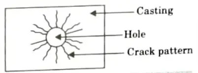
B. Brittle Coat Method:
- 1. In this procedure, brittle coating, sometimes referred to as brittle lacquer or stress coat, is used. It is essentially a mixture of limed wood rosin K, dibutyl phthalate, and carbon disulphide as a solvent. Commercial versions of the brittle coating are offered.
- 2. A coating that is suitable for the current humidity and temperature levels is chosen.
- 3. To create a bright background for the cracks to be easier to see, the job and the calibration strips are completely cleaned and coated with aluminium.
- 4. Brittle coating is sprayed over the job and the calibration strips, and they are then let to dry for 15 to 24 hours. When a coat or lacquer hardens, it becomes brittle.
- 5. A hole of approximately 3 mm in diameter is bored at the location in the project where the residual stress pattern and magnitude are to be evaluated.
- 6. Biaxial tensile stresses are applied to the calibration strip, and the initial cracking point and the strain measured on the strain scale are indicated.
- 7. By comparing the outcomes of the stress coat on the job with those of a calibration strip, residual stresses are computed.
- 8. Brittle coat method gives quantitative results accurate to within ±10 % and can be used to detect static and dynamic strains in tension or compression. In this method,
- 1. Usual gauge length is very small.
- 2. Approximate smallest measurable strain is 5x 10⁻⁴ mm/mm.
- 3. Approximate range of strains % is 0.05 to 0.15.
Q4. Explain in detail inspection before welding, inspection in between welding, inspection after welding.
Ans. A. Inspection before Welding:
- 1. Examine the dimensions, tolerances, process specifications, and other information on the welding joint drawing.
- 2. Choose the appropriate welding procedure using a simple way.
- 3. Configure the welding parameters, including the current, voltage, frequency, and polarity.
- 4. As per the specification, choose the material that is defect-free.
- 5. Choose the right size and flux coated electrode in accordance with the requirements (BIS specification).
- 6. Depending on the intricacy of the welding junction, choose the right jig and fixture.
- 7. Appropriate cooling, ventilation, and smoke control for welding joints.
B. Inspection in Between the Welding: It is the second stage of inspection and it involves:
- 1. The edge preparation (welding groove) must meet specifications.
- Tack welds need to be the right size, length, and pitch.
- 3. A welding technique that results in the least amount of distortion possible in the junction.
- 4. The fit up gap and welding location must comply with the welding procedure.
- 5. In multipass arc welds, the slag on the welding joint needs to be thoroughly removed after each pass.
C. Inspection after or Completion of Welding:
- 1. Find out of determine properties and weld quality of a weld object.
- 2. Find out suitability of weldment with the help of:
- i. Destructive testing, and
- ii. Non destructive testing.
Q5. Discuss in brief about salt spray test for testing corrosion.
Ans.
- 1. A common corrosion test technique to evaluate the corrosion resistance of materials and surface coatings is the salt spray test.
- 2. Often, the materials being examined are metallic and have a surface coating that is meant to protect the underlying metal from corrosion.
- 3. To assess if the coating is suitable for use as a protective finish, coated samples undergo an accelerated corrosion test that causes a corrosive attack.
- 4. After a predetermined amount of time, corrosion goods’ appearance is assessed.
- 5. The length of the test depends on how well the coating resists corrosion; generally speaking, the better the coating resists corrosion, the longer the testing period is before deterioration appears.
- 6. Popularity of salt spray testing is attributed to its affordability, speed, high level of standardization, and dependability.
- 7. Phosphorylated surfaces, zinc and zinc alloy plating, chromium, nickel, and organic coatings are typically tested with salt spray.
Q6. What do you understand by scanning electron microscope (SEM) ?
Ans.
- 1. A scanning electron microscope is a kind of electron microscope that scans the surface of a material to obtain images of it.
- 2. As the electrons contact with the atoms in the sample, different signals emerge that provide details about the sample’s surface topography and composition.
- 3. An image is created by combining the intensity of the detected signal with the position of the electron beam as it is scanned in a raster scan pattern.
- 4. In SEM, secondary electron detectors are used to catch secondary electrons that atoms stimulated by the electron beam produce.
- 5. Specimen topography influences, among other things, the quantity of secondary electrons that may be detected and, consequently, the signal intensity.

Advance Welding Btech Quantum PDF, Syllabus, Important Questions
| Label | Link |
|---|---|
| Subject Syllabus | Syllabus |
| Short Questions | Short-question |
| Question paper – 2021-22 | 2021-22 |
Advance Welding Quantum PDF | AKTU Quantum PDF:
| Quantum Series | Links |
| Quantum -2022-23 | 2022-23 |
AKTU Important Links | Btech Syllabus
| Link Name | Links |
|---|---|
| Btech AKTU Circulars | Links |
| Btech AKTU Syllabus | Links |
| Btech AKTU Student Dashboard | Student Dashboard |
| AKTU RESULT (One View) | Student Result |