With our thorough AKTU question paper and solution, you may explore the world of Advance Welding. Discover innovative procedures, equipment, and industrial practises. Improve your welding abilities and flourish in the field.
Dudes 🤔.. You want more useful details regarding this subject. Please keep in mind this as well.

Important Questions For Advance Welding:
*Quantum          *B.tech-Syllabus
*Circulars           *B.tech AKTU RESULT
* Btech 3rd Year
Section A: Advance Welding Short Answers
a. What is the function of flux in the welding?
Ans. The primary purpose of welding flux is to stop the filler and base material from oxidizing or corroding while welding.
b. What is the principle involved in resistance welding ?
Ans. Resistance welding refers to a collection of welding techniques in which pressure and heat are applied to the joint to cause coalescence. The heat is generated by the joint’s resistance to the passage of electric current in the circuit it is a part of. Filler metal is not required.
c. Draw the weld symbols for double U and single V joint.
Ans. Double U:

Single V Joint:
d. How radial friction welding is used to join the collars shaft and tube?
Ans.
- 1. In order to combine two pipe ends, solid bevelled rings must be rotated and compressed radially into a V-shaped preparation.
- 2. An internal support mandrel is offered at the weld location to stop the pipe ends from collapsing and metal from entering the bore.
- 3. By rotating a solid ring and using radial compression, metal bands can also be welded around solid or tubular cylinders.
e. What are the effects of gases in welding ?
Ans. Effects of gases in welding are as follows:
- 1. The droplet separation,
- 2. The size of the weld pool,
- 3. The shape and depth of the penetration, and
- 4. The welding speed, etc.
f. Define the health and safety in welding.
Ans.
- 1. Every welder should be aware of the potential health risks associated with fires, explosions, electricity, burns, welder flush, oxygen deprivation, poisonous fumes and gas particles, radiation, trips and falls, and take the necessary precautions to protect oneself from these risks.
- 2. To identify hazardous materials used in welding, check material safety data sheets. For example, use cadmium-free silver solders and asbestos-free electrodes.
- 3. For the protection of workers, all machinery with moving parts must be secured. To avoid slips and falls, keep the welding area free of tools, cables, hoses, and other obstructions.
g. How is the carbon equivalent value calculated ?
Ans.
- 1. The term “carbon equivalent” refers to an empirical weight percentage that compares the impacts of all the alloying materials used to create carbon steels to an equivalent amount of carbon.
- 2. In terms of welding, the parent metal’s ability to harden is determined by its carbon equivalent.
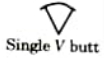
- 3. The content of carbon, manganese, chromium, molybdenum, vanadium, nickel, and copper are used to rate the weldability of a material.
- 4. It could be expressed as,
- 5. The carbon equivalent and the rate at which the steel is cooling from the transformation temperature affect the ability to create hard metallurgical components such as martensites or any other hard phases.
- 6. The potential for hard, brittle phases to occur during cooling increases with the carbon equivalent value, cooling rate, and cooling time.
h. Write short note on the bend test.
Ans.
- 1. With the aid of specific attachments, a bend test can be performed on a tensile testing equipment.
- 2. The bend test is a quick and low-cost test to use. The technique is quick and quite accurate in identifying most weld flaws.
- 3. Bend tests may be used to find a number of weld properties such as :
- i. Ductility of the welded zone,
- ii. Weld penetration,
- iii. Fusion,
- iv. Crystalline structure, and
- v. Strength.
- 4. The bend test aids in identifying the heat affected zone, the weld junction, and the weld metal soundness.
- 5. The test reveals the welded joint’s level of quality.
- 6. Any metal shattering will show faulty penetration or erroneous fusion.
- 7. Huge crystals typically signify a poor heat treatment following welding or an incorrect welding process. Good welds contain tiny crystals.
- 8. Bend tests may be categorized as:
- i. Free bend test, and
- ii. Guided bend test.
i. Describe the factors affecting weldability of copper alloys.
Ans. The factors affecting weldability of copper alloys are as follows:
- 1. Metallurgical compatibility,
- 2. Mechanical properties, and
- 3. Serviceability.
j. Describe the arc blow.
Ans.
- 1. Arc blow is the unintentional deflection or straying of a welding arc from its planned course.
- 2. Magnetic disturbances that throw off the symmetry of the self-induced magnetic field surrounding the electrode, arc, and workpiece are what cause an arc blow.
- 3. A hit to an arc may cause it to twist, deflect, or distort.
- 4. Arc blast gets worse when heavy metal plates are being welded with a DC power source in tight places and corners.
- 5. Since alternating current changes direction, reversing the magnetic field, AC arcs are less likely to blow than DC arcs.
- 6. As the direction of the current changes from positive to negative, the magnetic field expands, contracts, and then rebuilds. This phenomena prevents the magnetic field intensity from increasing to a level that would result in an arc blow.
- 7. In contrast, in DC welding, the magnetic field established in the workpiece (near the arc) steadily increases and the arc blow takes place.
Section B: Aktu Long Question with Answer
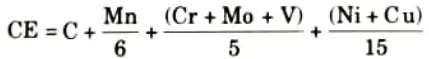
a. Describe TIG welding process with neat sketch. What are the advantages and limitation of TIG welding over MIG welding ?
Ans. A. TIG Welding :
- 1. Coalescence is created during the arc welding process by heating the joint with an electric arc created by striking a tungsten electrode against the joint.
- 2. In order to protect the molten weld pool from atmospheric contamination, a shielding gas is utilized (such as argon, helium, nitrogen, etc.).
B. Principle of Operation of TIG Welding:
- 1. The supplies of water, inert gas, and welding current are turned on.
- 2. Either a high frequency unit or a scrap piece of tungsten metal are used to strike the arc.
- 3. In this arc, the initial strike is made on a piece of scrap metal, and the arc is then shattered by lengthening it.
- 4. The tungsten electrode is warmed up by repeating this technique twice or three times.
- 5. Next, an arc is created between the electrodes and the job that has been previously cleaned.
- 6. By using this technique, work contamination, electrode tip cracking, and tungsten loss are avoided.
- 7. Gas tungsten arc welding is another name for TIG welding (GTAW).
- 8. GTAW can be powered by either an AC or DC power source.
- 9. Electrodes employed varies in diameter from 0.5 to 6.5 mm carrying current from 5 A to 6.5 A.
- 10. Among widely used arc welding methods, GTAW produces the highest quality welds and can be employed in any location.
C. Advantages of TIG Welding:
- 1. As no flux is used when welding refrigerator and air conditioner parts, there is no risk of flux entrapment.
- 2. The operator may exert superior control over the welding process due to clear view of the arc and the task.
- 3. For the high-quality welding of thin materials, this is ideally suited.
- 4. It is a particularly effective method for joining stainless steel and non-ferrous metals.
D. Disadvantages of TIG Welding:
- 1. The cost of the equipment is higher than for flux-shielded metal arc welding.
- 2. MIG welding is quicker than TIG welding for the same purposes.
b. The DC are current has voltage – length characteristics as V = (10 + 30L) volts. The characteristics of power source is V (60-0.071) volts. Determine the optimum are length and corresponding arc power.
Ans. Given: Voltage-length characteristics V = (10 +30L), Power
source characteristics V = (60-0.07I).
To Find: i Optimum arc length.
ii. Arc power.
1. The voltage-length characteristic is given as, V = (10 + 30L) ……(1)
2. The characteristics of power source is given as, V= (60-0.07I) …….(2)
3. Equating eq. (1) and eq. (2), we get
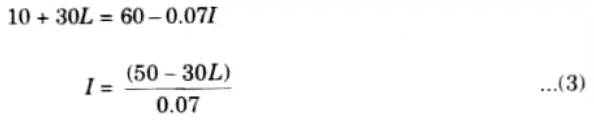
4. We know that, P = VI
6. Putting value of L in eq. (4), we get
P = 12.86 kW
c. Define residual stresses in welding. State and explain the major factors responsible for residual stress.
Ans. A. Residual Stress: When there is no external load present, the tension that remains within a welded, cast, or other construction causes it to self-balance.
B. Causes of Residual Stress in Welding: Residual stresses in the welding arise due to:
- 1. The weld heat source differentially heats the plates.
- 2. Plastic deformation that is not uniform.
- 3. The rate of cooling that is present during welding operations.
C. Types of Residual Stresses:
- i. Mechanical Residual Stresses:
- 1. The local heating and swift cooling of the weld metal during and after the welding, respectively, are to blame.
- 2. Metal expands owing to local heating, and contracts due to cooling. Stresses were created in the workpiece as a result of this local expansion and contraction process.
- ii. Metallurgical Residual Stresses:
- 1. When a phase changes during cooling from a temperature higher than the austenitizing temperature, this kind of residual stress is created.
- iii. Reaction Stresses:
- 1. When the weldment is already attached to other parts of the structure, reaction stress develops in the welding.
- 2. Because the weldment is already attached to another component of the structure, thermal expansion and contraction of that part of the structure occurs to the weldment, which causes reaction strains.
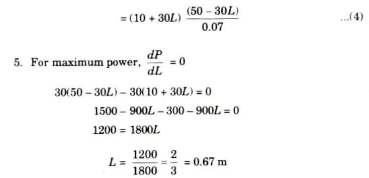
d. Briefly describe the various weld defect and distortion in welding and its causes and remedies.
Ans. Various defects in welding and its causes and remedies are as follows :
- i. Incomplete Penetration:
- 1. When the depth of the welded joint is insufficient, incomplete penetration happens.
- 2. The distance between the top surface of the base plate to the weld nugget’s greatest extent is referred to as penetration.
- a. Causes of Incomplete Penetration:
- 1. Improper joints.
- 2. Too large root face.
- 3. Less are current and faster arc travel speed.
- 4. Too large electrode diameter and longer are length.
- b. Remedies of Incomplete Penetration:
- 1. Increasing the heat input.
- 2. Reducing the travel speed during the welding.
- 3. Changing the joint design.
- 4. Ensuring that the surfaces to be joined fit properly.
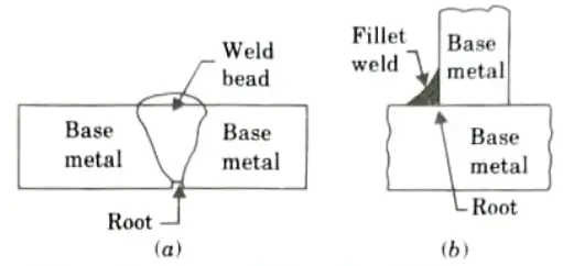
- ii. Inclusion:
- 1. Inclusions can take the shape of slag or any other foreign substance that cannot float on the surface of the weld metal when it solidifies and becomes imprisoned inside of it.
- 2. Inclusions weaken and reduce the joint’s strength.
- a. Causes of Inclusion:
- 1. An excessively high or low arc current.
- 2. An electrode diameter that is too large and a long arc.
- 3. Multipass welding techniques don’t chip and clean the previous passes enough.
- 4. Inadvertent tack weld placement.
- 5. The joint’s included angle is too narrow.
- b. Remedies of Inclusion:
- 1. Using a wire brush to clean the weld bead surface before the next layer is deposited.
- 2. Supplying enough shielding gas.
- 3. Redesigning the joint to allow enough room for the proper handling of the pool of molten metal during welding.
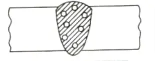
- iii. Porosity and Blowholes:
- 1. Blowholes are relatively larger isolated holes or cavities compared to porosity, which is a collection of microscopic voids.
- 2. They are mainly generated due to the entrapped gases.
- a. Causes of Porosity and Blowholes:
- 1. Use of improper electrode and longer arc.
- 2. Faster arc travel speeds.
- 3. Too low and too high arc currents.
- 4. Unclean job surface i.e., presence of scale, rust, oil and grease etc., on the surface of the job.
- 5. Due to the gas entrapment during solidification of weld.
- b. Remedies of Porosity and Blowholes:
- 1. Appropriate electrode and filler metal selection.
- 2. Better welding methods, such as preheating the weld region or speeding up the heat input.
- 3. Thorough cleaning and keeping impurities out of the weld zone.
- 4. Slower welding to give the gas time to escape.
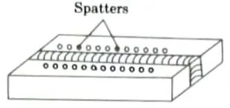
- iv. Spatter:
- 1. Little metal fragments known as “spatters” are ejected from the welding arc during the process and land on the surrounding base metal along the length of the weld bead.
- a. Causes of Spatter:
- 1. Excessive arc current.
- 2. Use of longer arc.
- 3. Use of damp electrodes.
- 4. Electrodes being coated with improper flux ingredients.
- 5. Arc blow making the arc uncontrollable.
- b. Remedies of Spatter:
- 1. Use proper are current to weld.
- 2. Use proper are length.
- 3. Use fresh electrodes.
- 4. Use of AC power to reduce arc blow.
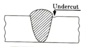
- v. Undercut:
- 1. An undercut is a type of weld fault in which the source metal develops a groove along the sides of the weld bead.
- 2. The plate’s thickness and weld strength are both decreased by grooves.
- a. Causes of Undercut:
- 1. Wrong manipulation and inclination of electrode and excessive weaving.
- 2. Too large electrode diameters.
- 3. Higher current.
- 4. Longer arc.
- 5. Faster arc travel speed.
- b. Remedies of Undercut:
- 1. Use proper arc current.
- 2. Use proper electrode.
- 3. Weaving should be proper and as per requirement.
- 4. Use proper arc travel speed.
- vi. Hot Tear:
- 1. With this welding flaw, the hot metal that has been deposited begins to produce cracks from the nearby edge, and when the metal has set, the crack grows.
- 2. Hot tearing, also known as solidification cracking, results from tearing of the grain boundaries of welded metal while the metal is still in a plastic condition and solidification has not yet fully taken place.
- a. Causes of Hot Tear:
- 1. Improper selection of electrode material.
- 2. Welding current is not proper.
- 3. Improper electrode thickness.
- b. Remedies of Hot Tear:
- 1. Choose the right electrode material.
- 2. The welding current should be optimal for the situation.
- 3. Depending on the base metal to be welded, the electrode thickness should be optimal.
- Distortion:
- 1. Distortion is the shift in the two plates’ locations between before and after welding, as well as their altered shape.
- 2. Because there is a significant temperature difference along the joint, different parts of the base metal can expand or contract at any time, including the weld bead. Distortion results from this phenomenon.
e. Write short note on :
i. Gas metal reaction.
ii. Slag metal reaction.
Ans. i. Gas metal reaction.
- 1. In physical (endothermic) solution, no compound is formed.
- 2. It does not inhibit fusion, but can result in porosity.
- 3. Porosity may be caused:
- i. A result of hydrogen, nitrogen, or oxygen gas supersaturating the molten weld metal.
- ii. By reaction between two gases.
- 4. Heat affected zone may also get embrittled in some cases.
- 5. The mechanism of endothermic reaction is:
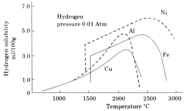
- i. By using metal circulation, gas is absorbed up to its maximum solubility and disseminated throughout the weld pool.
- ii. Fig. shows the solubility of hydrogen in various materials at different temperatures.
- iii. Reaction takes place between gas and metal and between two gases, e.g.,
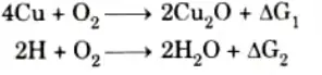
Where, 𝚫G1 and 𝚫G2 are the free energy changes for two reactions.
- iv. Evolution of gas dissolved in weld pool:
- 1. The gas that has been dissolved in the weld pool’s high temperature area and is moved to cooler areas will generally be evolved after forming a supersaturated solution.
- 2. The presence of appropriate nuclei and a minimum level of supersaturation are required for gas evolution to occur.
- 3. If gas bubbles are caught in a metal that is rapidly freezing, porosity will result.
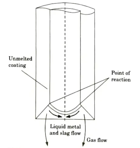
ii. Slag metal reaction.
- 1. The composition of the flux or electrode coating plays a significant role in determining the nature of slag metal reactions.
- 2. Fig. shows the shape of the electrode tip used in shielded metal arc welding. Inside the cone-shaped covering, a liquid drop develops. Slag and metal immediately interact at the point where the cone and liquid meet.
- 3. If alloying elements are supplied via the coating, they dissolve at this stage and are well combined, resulting in a nearly uniform drop when it separates.
- 4. This suggests that the drop’s circulation is circulating quickly as a result of electromagnetic effects or drag from gas produced by the coating. The liquid metal is heated to a high temperature concurrently.
- 5. The drop profile is not at all as regular in practise as it is in Fig. It is always moving, just like the arc root. Yet, this has no effect on the arrangement’s fundamental geometry.
- 6. In submerged arc welding, the arc is enclosed in a hollow filled with liquid slag, and the metal drops frequently pass through the cavity or sporadically go around the wall of the cavity.
- 7. Once more, it is expected that considerable slag metal interactions occur due to the high temperature and the huge surface-to-volume ratio of the drop.
- 8. Slag metal reactions may also be affected by the submerged arc welding technique’s deep penetration feature.
Section 3: Selection Criteria of Welding Process
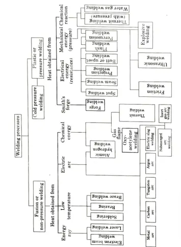
a. Briefly classify the process selection criteria of welding process.
Ans. A. According to Source of Energy Employed for Heating: These may be divided into two groups as follows:
- i. Pressure Welding:
- 1. In these procedures, the components that need to be linked are heated until they are in a plastic condition and then pressed, such as during forge welding or thermite pressure welding, to produce the joint.
- ii. Fusion Welding:
- 1. Without applying pressure, the material at the junction is heated to a molten condition and allowed to solidify to create the joint.
- 2. Although some joints can be created without the use of a filler metal, most welds require the use of a filler metal to close the gap between the components.
- 3. The base metal’s composition should match that of the filler metal that is deposited. Examples include electric arc welding and gas welding.
B. According to the Composition of Filler Metal: These may be divided into three groups as follows:
- i. Autogenous Welding:
- 1. In these procedures, like cold and hot pressure welding and electric resistance welding, no filler metal is applied to the joint interface.
- ii. Homogeneous Welding:
- 1. Similar to the parent metal, filler metal is added throughout these procedures, such as when welding plain low carbon steel with a low carbon welding rod or 70-30 brass with a 70-30 brass welding rod.
- iii. Heterogeneous Welding:
- 1. Some procedures, such as brazing and soldering, involve the use of a filler metal that is distinct from the parent metal.
b. Classify the different types of metal transfer used in various types of arc welding process with neat sketch.
Ans.
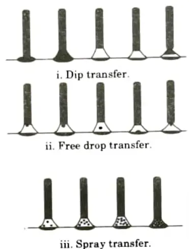
- 1. Metal transfer from electrode to workpiece is defined as the process by which an electric arc is created between the workpiece and consumable electrode, causing the electrode to melt into a spherical shape, hang towards the job, and eventually fall on the workpiece.
- 2. Metal is transferred in arc welding in three ways:
- i. By dip transfer,
- ii. By free drop (large drop) transfer, and
- iii. By spray (small drop) transfer.
- 3. At the initial step of arcing in dip transfer, a globule of molten metal forms at the electrode’s tip.
- 4. After that, it grows and lengthens, comes in contact with the molten pool, and then separates from the electrode.
- 5. Because the globules are not instantly released from the electrode after the procedure, a momentary short circuit results.
- 6. To finish welding, the procedure is repeated multiple times.
- 7. In free drop transfer, the molten metal pool temporarily (but partially) short circuits the electrode, causing a drop of molten metal somewhat smaller in diameter than the air gap to fly off from the electrode end.
- 8. In spray or small drop transfer, the transfer occurs in the form of minute droplets that fly freely from the electrode to the molten pool. These droplets are much smaller in diameter than the arc length.
- 9. The end job will have higher mechanical advantages and the transfer rate is stable.
- 10. The three transfer methods are shown in Fig.
Section 4: Laser Beam Welding
a. Describe the laser beam welding. Explain the principle behind the generation of laser with neat sketch and also write the various application of laser beam welding.
Ans. A. Laser Beam Welding and Principle of Generation of Laser:
a. Laser Beam Welding:
- 1. To weld metal components using a laser beam, one must direct the coherent monochromatic light beam that the laser source emits onto the metal pieces. This causes the metal to heat up on the surface and conduct heat through it.
- 2. Gas lasers and ruby lasers are two types of lasers that are employed in solid state lasers.
- 3. The laser crystal (Ruby) is shaped like a cylinder, with flat, precisely parallel ends that are silvered to create mirror-like reflecting surfaces.
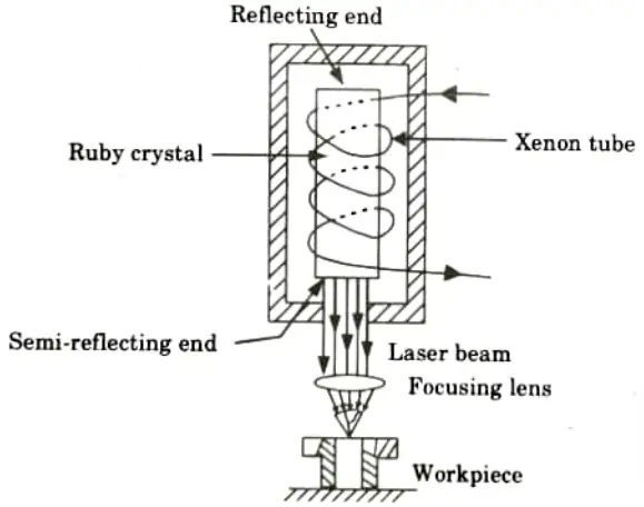
- 4. The output end of the crystal has a small aperture that passes through the mirror on its axis.
- 5. The Cr ions in the crystal become excited when it is exposed to high intensity white light from a xenon or krypton lamp.
- 6. More energy is available from the excited ions, part of which is sent off as a red fluorescent light.
- 7. Between the two ends of the crystal, this light is bounced back and forth, striking additional Cr ions in its course.
- 8. When more and more Cr ions are excited by these collision-induced red light emissions, the number of collisions increases, resulting in a burst of red light passing through the crystal’s output end’s tiny mirror aperture.
- 9. The beam generated is incredibly thin and can be focussed with an optical lens to a precise location.
b. Principle of Generation of Laser Beam:
- 1. In this, capacitor bank stores electrical energy.
- 2. It is charged by a high voltage power supply.
- 3. Xenon converts a significant percentage of the electrical energy into white light flashes when exposed to electrical discharge from the capacitors.
- 4. The crystal’s chromium atoms are energized and pumped to a high energy level as the ruby is exposed to the powerful light flashes.
- 5. With the evolution of heat, these chromium atoms fall right away to a lower energy level, and with the evolution of a specific amount of radiation in the form of red fluorescent light, they finally fall back to their original condition.
B. Application of Laser Beam Welding :
- 1. Cutting and welding of material.
- 2. Welding of nuclear plant components.
- 3. For splicing leads on tiny electronic parts and in integrated circuitry in the electronics sector.
- 4. Trans mission component for a car.
- 5. For welding of high melting point metals.
b. Define the magnetically impelled arc butt (MLAB) welding procedure, limitation and application of this process.
Ans. A. Magnetically Impelled Arc Butt Welding:
- 1. Magnetically impelled arc butt (MIAB) welding is a solid state welding technique in which the arc is rotated around the tube to help ensure that surfaces are heated uniformly.
- 2. The MIAB welding technique is a single shot that is highly quick 22 seconds for a pipe thickness of 6 mm and easily automatable because it requires no manual skill.
- 3. It results in a solid state bonding that promotes superior mechanical characteristics. It also creates the potential of metal joints with different compositions.
- 4. MIAB welding is significantly simpler and less expensive since, unlike friction welding, it does not require component rotation.
- 5. MIAB welding may also result in less internal flash, a shorter weld time, less metal loss, homogeneous heating, and less machine upkeep.
- 6. There are six stages to the MIAB welding process, which include arc initiation, arc rotation’s start, transitory rotation, and stable rotation. The other two stages include unstable rotation and tube upsetting.
- 7. The MIAB welding technique is utilised extensively in the oil, gas, power, and defence industries and is regarded as a superior alternative to friction, flash, resistance, and butt welding.
B. Limitations:
- 1. Cannot be used for thick components.
- 2. It is limited for a few alloys.
C. Applications:
- 1. Used in low alloy and low and medium carbon steel welding.
- 2. Used in the welding of axle casings, propeller shafts, drive shafts, etc.
Section 5: Weld Thermal Cycles
a. Explain the factor affecting changes in microstructure and mechanical properties of heat affected zone.
Ans. Various factors affecting changes in microstructure and mechanical properties of HAZ are as follows:
- 1. The welding procedure.
- 2. In the case of coated electrodes, the composition of the flux and the filler rod.
- 3. The environment in which the weld is created, namely the levels of oxygen and nitrogen.
- 4. The base metal’s chemical makeup.
b. Discuss in detail about weld thermal cycles with neat sketch and also mention the factor affecting change in microstructure and HAZ.
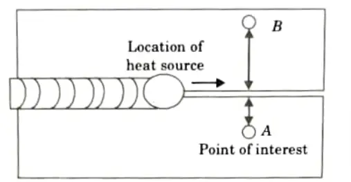
Ans. A. Weld Thermal Cycle:
- 1. The temperature of a specific area within and surrounding the weld varies as a function of welding duration as shown by the weld thermal cycle.
- 2. As the heat source (welding arc or flame) approaches the area of interest, the temperature gradually rises during the heating phase and then gradually drops during the cooling regime.
- 3. A typical weld thermal cycle, as illustrated in Fig., includes the rate of heating, the time needed to reach the peak temperature, and the rate of cooling.
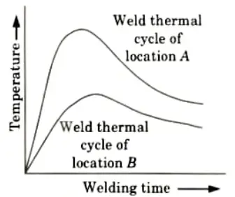
- 4. Each location N point gives a different and distinctive weld thermal cycle since the distance of the point of interest from the weld centre line immediately impacts all the above characteristics (heating and cooling rate, peak temperature, etc.), as shown in Fig.
- 5. In general, an increase in distance of point of interest away from the weld centre line:
- i. Decreases the peak temperature.
- ii. Decreases the rate of heating and cooling.
- iii. Increases time to attain peak temperature.
- iv. Decreases rate of cooling with increase in time.
B. Factor Affecting Change in Microstructure and HAZ:
- 1. The welding procedure.
- 2. In the case of coated electrodes, the composition of the flux and the filler rod.
- 3. The environment in which the weld is created, namely the levels of oxygen and nitrogen.
- 4. The base metal’s chemical makeup.
Section 6: Types of Weld Joint
a. Discuss about the different types of weld joint with neat sketch.
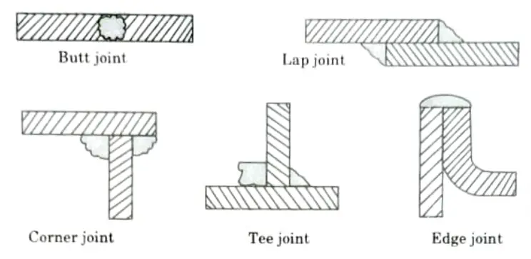
Ans. A. Types of Weld Joint: Various types of welded joints used in weld design are as follows:
- i. Butt Joint:
- 1. Compared to single V, U, J, or bevel joints, square butt joints (with or without gap) are advised for thinner plate thicknesses (up to 4.8 mm) and substantially lower loading.
- 2. For larger plate thicknesses, double joints are preferred to single joints.
- 3. The V joint has a significantly wider range of uses and applications than other joints.
- 4. For plates with thicknesses ranging from 10 mm to 35 mm and exposed to medium loading, bevel joints are preferred.
- 5. When it comes to making high-quality joints in particular pressure vessels with plate thickness ranging from 10 mm to 20 mm, U joints are recommended over V joints.
- 6. J joints are recommended for normal loading in some pressure vessels.
- 7. Among the double joints, double V Joint is employed under most severe loading conditions.
- ii. Lap Joint:
- 1. All thicknesses utilise single and double fillet joints.
- 2. When a joint is subjected to heavy loading, a double fillet joint is preferable to a single fillet joint.
- 3. In conditions of bending, fatigue, or impact loading, single fillet joints are not advised on plates.
- 4. Plug welding is used to give the construction more strength. When the bottom or second plate cannot be easily reached, a plug weld joint is employed.
- iii. T Joint:
- 1. When lower plate thicknesses are subjected to low or no bending strain circumstances, a single fillet T joint is suggested.
- 2. For the most demanding loading circumstances, a double T joint is advised.
- 3. In T joints, electrode consumption reduces and edge preparation costs rise.
- iv. Corner Joint:
- 1. Close and half-open corner joints on plates with a smaller thickness that aren’t subject to heavy loads.
- 2. Under extreme load circumstances, full open corner joints can be employed on plates of all thicknesses.
- 3. When the connection is welded from both sides, the load bearing capability rises.
- v. Edge Joint:
- 1. Two metal pieces are lapped with their edges aligned, and the edges are then united by welding.
- 2. Fillet welds, such as corner joints, T joints, lap joints, etc., are the least expensive to fabricate since there is no need for edge preparation and the setup is straightforward.
B. Sketch:
b. Explain the following:
i. Dye penetrant testing.
ii. Discontinuities in weld and their causes.
iii. Inspection of weld.
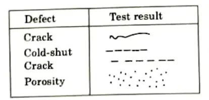
Ans. i. Dye penetrant testing.
- 1. It is a non-destructive method of testing to find faults such cracks, seams, laps, absence of bond, porosity, cold shuts, etc. that are visible on the surface.
- 2. When applied to a preventive or impermeable surface in a dye penetrant test, the vividly coloured red penetrant liquid has the ability to penetrate surface faults.
- 3. The working steps of dye penetrant tests are as follows:
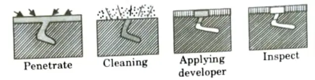
- i. To start, use a piece of cloth to wipe the component’s surface clean and free of dust and debris.
- ii. Remove scale, rust, paint, and other contaminants from the component’s surface with a soft wire brush.
- iii. Spray the cleaner on the surface to remove oil and grease.
- iv. Next, evenly cover the area that needs to be tested with the dye penetrant. Let the colour to soak into the cracks for 3 to 5 minutes.
- v. Use a ray stone to remove any surplus penetrant on the surface.
- vi. Reapply the cleaner to the surface to get rid of the remaining red colour.
- vii. Evenly spray a substance known as developer across the surface. This will provide an even, thin covering across the surface that will be examined. In order to provide a visible sign of the faults, this layer absorbs the penetrant from the fractures, causing red spots or lines to form on the surface.
- viii. The red dye absorbed by the white absorbent will show any cracks, if there are any.
4. For dye penetrant test:
ii. Discontinuities in weld and their causes.
A. Discontinuities in Weld:
- 1. Any stoppage in the regular flow of the structure in a weldment is referred to as a weld discontinuity (also called a weld defect).
- 2. The physical, mechanical, or metallurgical properties of the material or weldment may be the source of the interruption.
- 3. They can result from improper or erroneous welding patterns, etc., in the provided weld metal.
- 4. The discontinuity might not be of the intended size and quality for the weld bead form. They could develop outside or inside the metal used for the weld.
- B. Causes:
- 1. Careless or improper technique that leads the arc to land in the incorrect spot.
- 2. Forgetting to clean the basic metal of contaminants like dirt.
- 3. Not applying adequate welding current to the junction or preheating thick metals.
iii. Inspection of weld.
A. Inspection before Welding:
- 1. Examine the dimensions, tolerances, process specifications, and other information on the welding joint drawing.
- 2. Choose the appropriate welding procedure using a simple way.
- 3. Configure the welding parameters, including the current, voltage, frequency, and polarity.
- 4. As per the specification, choose the material that is defect-free.
- 5. Choose the right size and flux coated electrode in accordance with the requirements (BIS specification).
- 6. Depending on the intricacy of the welding junction, choose the right jig and fixture.
- 7. Appropriate cooling, ventilation, and smoke control for welding joints.
B. Inspection in Between the Welding: It is the second stage of inspection and it involves:
- 1. The edge preparation (welding groove) must meet specifications.
- Tack welds need to be the right size, length, and pitch.
- 3. A welding technique that results in the least amount of distortion possible in the junction.
- 4. The fit up gap and welding location must comply with the welding procedure.
- 5. In multipass arc welds, the slag on the welding joint needs to be thoroughly removed after each pass.
C. Inspection after or Completion of Welding:
- 1. Find out of determine properties and weld quality of a weld object.
- 2. Find out suitability of weldment with the help of:
- i. Destructive testing, and
- ii. Non destructive testing.
Section 7: Metallizing Process
a. What is metallizing process ? How the surface of work must be prepared for this process? Also describe the nature of bond between sprayed metal and work.
Ans. A. Metallizing Process:
a. Principle of Metallizing Process:
- 1. The material to be sprayed is delivered into the oxy-acetylene flame in the form of powder or wire. There, it melts due to the heat of the neutral flame, is atomized and thrown onto the surface of the base metal by a stream of compressed air, spreads out and connects with projections embedded in pits, and instantly freezes when it comes into contact with the base metal.
- 2. To create a cohesive structure, separate particles overlap and entangle with one another.
- 3. The material is typically applied in layers that are no thicker than 0.25 mm.
b. Working of Metallizing Process:
- 1. This comprises of a wire-type spray pistol with a hole through the middle of its tip that looks like an oxy-fuel gas torch.
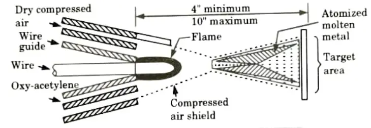
- 2. The cannon also has a mechanism that drives two knurled rolls that feed wire into the flame; wire reels and straighteners are utilized in this setup.
- 3. A jet of compressed air is directed to the tip of the gun through an air cap, picking up the molten metal and projecting it onto the base structure after being thoroughly atomized.
- 4. The liquid metal atomizes the molten wire metal that has been melted by the oxy-acetylene flame and cools the substrate, keeping the temperature below 205 °C. Dry compressed air forms an air envelope around the outside of the flame.
- 5. Molten metal particles travelling to the base metal are likewise accelerated by compressed air, depositing them there.
B. Preparation of Surface: In the metallization process, the surface is first cleaned by abrasive blasting to eliminate flaws and irregularities, then heated to create molten particles that are sprayed onto the surface.
C. Nature of Bond between Sprayed metal and Work:
- 1. The bond in metal spraying is solely mechanical.
- 2. The process is essentially cold even if each small particle that reaches the surface is molten because there isn’t enough heat to initiate welding to the surface.
- 3. As a result, mechanical interlocking of metal particles with a smooth and rough surface typically leads to adhesion.
b. Discuss the effect of alloying element on the weldability. Explain the welding of dissimilar metal briefly.
Ans. A. Effect of Alloying Element on the Weldability:
- 1. Alloying elements increase or decrease hardenability of the HAZ. C, Mn, Mo, Cr, V, Ni and Si have greatest effect on the hardenability of steel.
- 2. Alloying elements provide grain refinement. Al, V, Ti, Zr and N are the grain refiners for carbon and low alloy steels.
- 3. Alloying components regulate the temperature at which ductile materials become brittle.
- 4. By strengthening the metal through solid solution hardening, alloying elements create substitutional alloys.
- 5. In order to boost mechanical characteristics via lattice distortion, alloying elements create interstitial alloys.
- 6. Alloying elements diminish segregation, generate carbides, and age-hardening precipitates.
- 7. Alloying components also refine grain.
- 8. Alloying elements allow molten metal to deoxidize without losing the primary alloying elements. Due to their greater affinity for oxygen than iron, Ti, Zr, Al, and Si serve as deoxidizers in low alloy and carbon steels.
B. Welding of Dissimilar Metal: Various techniques for welding the dissimilar materials are as follows:
- i. Resistance Welding:
- 1. Since the issue of fluxing or the provision of an inert atmosphere does not arise and the techniques readily available frequently minimize the risk of the formation of brittle intermetallic compounds within the joint, resistance welding is frequently easier to perform than are welding in producing satisfactory joints between dissimilar metals.
- 2. For instance, when copper and aluminium are fused together, they generate a number of brittle phases, but flash-butt welding of the two metals is commonly used because these phases are pushed out of the joint when the upset force is applied.
- 3. Dissimilar metals are welded using both spot welding and projection welding.
- ii. Solid-State Welding:
- 1. Solid-state welding processes include:
- i. Pressure welding with or without controlled atmospheres.
- ii. Ultrasonic welding.
- iii. Friction welding.
- iv. Diffusion bonding.
- 2. It is necessary that the surfaces should be clean and be in intimate contact.
- 1. Solid-state welding processes include:
- iii. Brazing:
- 1. Brazing is crucial for bonding dissimilar metals because it prevents alloying between the metals and the formation of inappropriate phases when done properly.
- 2. Normally, annealing should be done on materials that are prone to intergranular penetration before brazing.
- 3. Copper, copper alloys, steels of all types, heat-resistant alloys, and nickel alloys can be joined using zinc carrying silver solders and copper-zinc alloys.
6 thoughts on “Advance Welding: Solutions of Aktu Question Paper”