Strength of Material Important Questions Aktu, Solved Question Paper , Quantum Book Pdf 2022-23, Repeated Most important Questions, Syllabus, Aktu Notes
Dudes 🤔.. You want more useful details regarding this subject. Please keep in mind this as well.

Important Questions For Strength of Material:
* Aktu Quantum          * B.tech-Syllabus
* Circulars                     * B.tech AKTU RESULT
* Btech 3rd Year
Section A: Strength of Material Aktu Short Important Notes Pdf
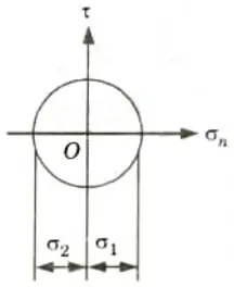
a. Draw Mohr’s circle for pure shear in a two-dimensional stress field.
Ans.
b. Why are stresses called tensor?
Ans. Stresses are called tensor because they can produce strain in all three directions.
c. How differential equation of elastic curve is used to find slope and deflection of beam?
Ans. The slope and beam deflection are determined by the differential equation’s first and second integrations, respectively. Boundary conditions are used to find the integration constants.
d. Explain section modulus and its significance.
Ans. Section Modulus: The ratio of a section’s moment of inertia around the neutral axis to the distance of the outermost layer from the neutral axis is what is meant by this word. It is denoted by Z.
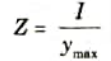
Significance: It is direct measure of the strength of the beam.
e. What are the types and basic functions of springs?
Ans. Types of Spring: Following are the different types of springs :
- a. Helical springs,
- b. Leaf springs,
- c. Torsion springs,
- d. Circular springs,
- e. Belleville springs, and
- f. Flat springs.
Functions of Spring: Springs perform the following functions:
- a. To absorb shock or impact loading.
- b. To measure forces as in spring balances, and
- c. To store energy as in clock springs.
f. Explain slenderness ratio and its importance in the classification of columns.
Ans. Slenderness Ratio: It is the ratio of the column’s unsupported length to its minimal gyrating radius at its cross-sectional ends. Its symbol is “k,” and it has no dimensions.
Importance:
- 1. The slenderness ratio of a column indicates whether the column will buckle.
- 2. The tendency of a column to fail via buckling effect in that direction increases with the slenderness ratio.
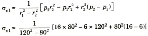
g. Derive the expression for finding circumferential stress in a thin cylinder subjected to internal fluid pressure.
Ans. 1. Consider a thin cylindrical shell subjected to an internal pressure as shown in Fig.(a) and (b).
2. We know that as a result of the internal pressure, the cylinder has a tendency to split up into two troughs as shown in the Fig.
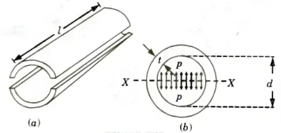
3. Let, l = Length of the shell, d = Diameter of the shell,
t = Thickness of the shell, and
P = Intensity of internal pressure.
4. Total pressure along the diameter (say X-X axis) of the shell,
P = Intensity of internal pressure x Area
= p x d x l
5. Circumferential stress in the shell
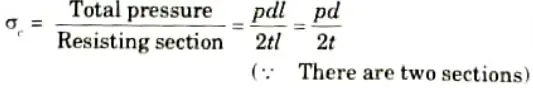
This is a tensile stress across the X-X. It is also known as hoop stress.
h. Explain the purpose of compounding thick cylinders.
Ans. The cylinders are compounded with a purpose to increase the pressure bearing capacity of a single cylinder.
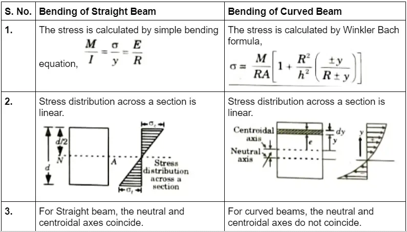
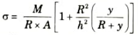
i. Write the expression for finding stresses due to bending in straight and curved beams.
Ans.
j. Differentiate between pure and unsymmetrical bending.
Ans.
| S. No. | Pure Bending | Unsymmetrical Bending |
| 1. | A member is considered to be in pure bending if it is subjected to equal and opposite couples acting in the same longitudinal planes. | Unsymmetrical bending is defined as bending where the plane of loading or the plane of bending does not contain the main centroidal axis of the cross-section. |
Section B: Strength of Material Quantum Pdf book
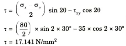
a. At a point in a beam the normal stress along the length is 80 N/mm2. The shear stress at that point is positive (CW) of magnitude 35 N/mm2. Find the stresses on a plane whose normal is inclined at 30° to the longitudinal axis. Also find the principal stresses and planes on which they act.
Ans. Given: 𝜎x = 80 N/mm2, 𝜏xy = 35 N/mm2, 𝜃 = 30°
To Find: i. Stresses on inclined plane.
ii. Principal stresses and their plane.
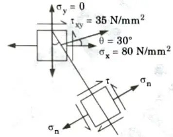
1. Normal stress is given by,
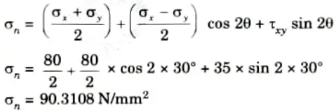
2. Shear stress is given by,
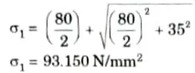
3. Principal Stresses are given by,
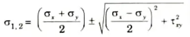
i. Major principal stress,
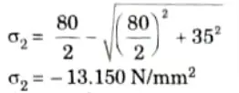
ii. Minor principal stress,
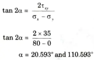
4. Plane of inclination is given by,
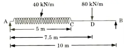
b. A simply supported beam of span 10m carries a uniformly distributed load of 40 kN/m over a length 5m of its left half and a concentrated load of 80 kN at 7.5 m from the left end. Determine the slopes at the ends, and the deflections under the concentrated load and at mid-span.
Take E = 2 x 10⁶ kN/m2 and I = 56,000 cm2.
Ans. Given: Span of beam, l = 10 m, E = 2 x 10⁶ kN/m2, I = 56000 cm4 56 x 10-5 m4.
1. The given problem is shown in Fig.
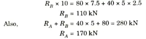
2. To calculate reaction at B, taking moments about A, we get
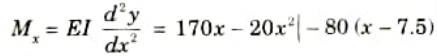
3. Using Macaulay’s method considering any section x-x at a distance x from the end A; the bending moment at the section x-x,
4. On integration, we get

5. Integrating eq. (2.17.1), we have

6. Now using boundary conditions,
At x = 0, y = 0, from eq. (2.17.2), we get
C2 = 0
Also at x = 10, y = 0, from eq. (2.17.2), we get
C1 = -1145.83
7. Put the value of C1 and C2 in eq. (2.17.2), we get

8. Slope at end A can be obtained by putting x = 0 in eq. (2.17.1), we get
9. Slope at end B can be obtained by putting x = 10 in eq. (2.17.1), we get
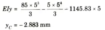
10. Deflection at point C, i.e., (x = 5),
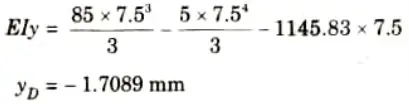
11. Deflection at point D, i.e., (x = 7.5),
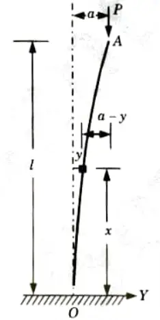
c. Derive the expression for the critical buckling for a column having one end fixed and the other end free.
Ans. 1. Take Y-axis towards right for positive value of y.
2. Viewing from the left end, P provides a clockwise bending moment P(a – y) on the left portion and is thus positive then,
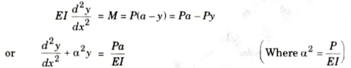
3. The solution is
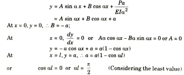
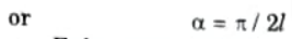
Euler crippling load,
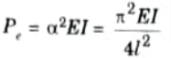
From Euler’s formula,
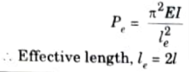
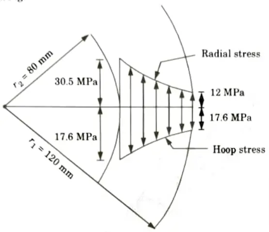
d. The maximum stress permitted in a thick cylinder, radii 8 cm and 12 cm, is 20 N/mm2, the external pressure is 6 N/mm2 what internal pressure can be applied ? Plot curves showing the variation of hoop and radial stresses through the material.
Ans. Given: Internal radius, r2 = 8 cm = 80 mm, External radius, r1 = 12 cm = 120 mm, External pressure, p1 = 6 N/mm2
Maximum hoop stress, 𝜎x2 = 20 N/mm.2
To Find: Internal pressure p2, hoop stress at outer face 𝜎x1
1. Hoop stress at inner face,
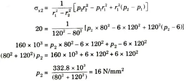
2. Hoop stress at outer face,
𝜎x1 = 10 N/mm2 (Tensile)
3. The variation of hoop and radial stresses through the material is shown in Fig.
e. Explain the following:
i. Why is the knowledge of shear center of a beams being important ?
Ans. 1. The junction of the bending axis and the transverse section plane defines the shear centre.
2. The shear centre of a section is the location at where the total shear forces generated by adding the shear stresses across the section balance the applied force.
3. It is crucial to understand the shear centre since it indicates the location where the beam won’t twist.
ii. Why position of neutral axis from centroid for curved beams in Winkler Bach theory is given as
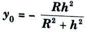
Ans. 1. As we know that the stress acting on the beam is
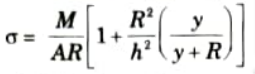
2. At neutral axis stress will become zero, so 𝜎 = 0
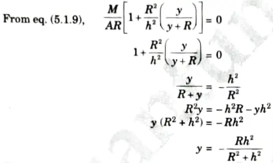
3. This equation shows that y is negative means the position of neutral axis is below the centroidal axis.
Section 3: Strength of Material Important Aktu Questions
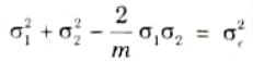
a. At a point in a steel member, the major principal stress is 200 N/mm2, find the minor principal stress which is compressive. If the tensile yield stress is 250 N/mm2 at which yielding commence, using
i. Maximum strain energy (Haigh) theory
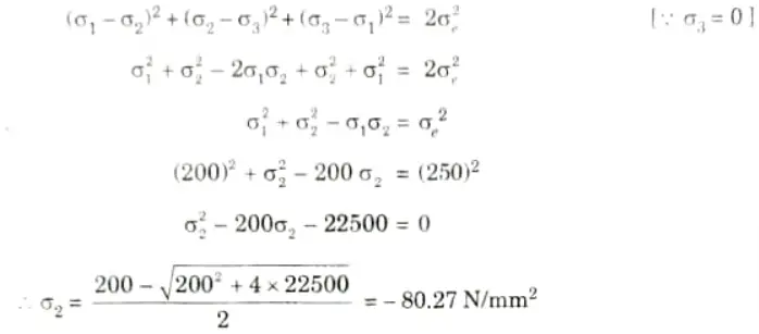
ii. Maximum shear strain energy (Von Mises) theory
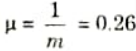
Ans. Given: 𝜎1 = 200 M/mm2, 𝜎e = 250 N/mm2
Data Assumed:
To Find: Minor principle stress using Haigh theory and Von Misses theory.
i. According to Maximum Strain Energy Theory:
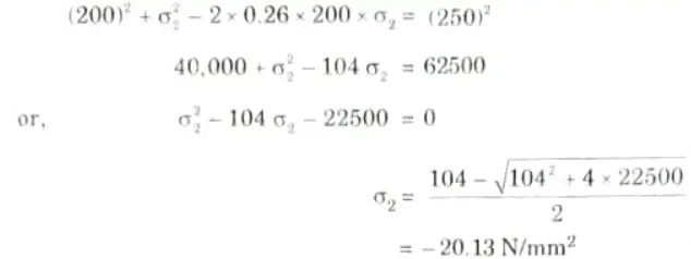
ii. According to Maximum Shear Strain Energy Theory:
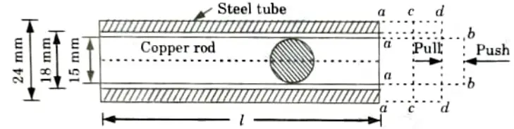
b. A steel tube with 24 mm external diameter and 18 mm internal diameter encloses a copper rod of 15 mm diameter to which it is rigidly joined at each end. If at a of 10 temperature °C, there is no longitudinal stress, calculate the stresses in the rod and the tube when the temperature is raised to 200 °C.Take ES = 2.1x 10⁵N/mm2. EC = 1x 10⁵ N/mm2, 𝛼S = 11x 10-6/°C, 𝛼C = 18 x 10-6/°C.
Ans. Given: DS = 24 mm, ds = 18, DC 15 mm, t1 = 10 °C, t2 = 200 °C,
Es = 210 kN/mm2, 𝛼S = 11 x 10-6/°C
Note: Since the given value of E and a for steel and copper are same hence it is not possible to solve the numerical.
So assuming the value of E and a for copper as
EC = 110 kN/mm2, 𝛼C = 18 x 10-6/°C and solving the numerical
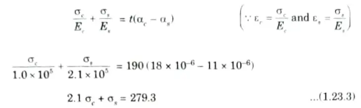
1. Rise in temperature, t = t2 – t1 = 200- 10 = 190 °C
2. Stresses in the Rod and the Tube, 𝜎c, 𝜎s:
i. Fig. since 𝛼C > 𝛼S elongation of copper will naturally be more than that of steel for the same rise of temperature but since they are rigidly jointed at each end, the copper rod will venture to pull the steel tube along with it; whereas the steel tube will struggle to bring the copper rod back.
ii. Ultimately, they will compromise and become stable at certain common position.
3. Extension of copper rod when free to expand = ab = l 𝛼C .t
Extension of steel rod when free to expand = ac = l 𝛼S = t
4. Being connected together, suppose they compromise at the position dd; which means that steel tube will be pulled from c to d, and the copper rod pushed back from b to d. In this way steel is under tension and the copper is under compression.
5. Compressive strain in copper rod,
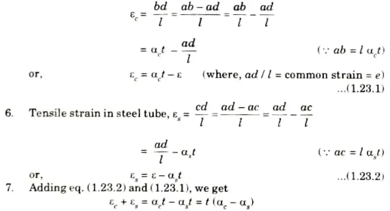
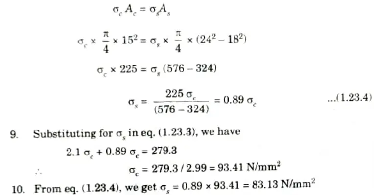
8. But at the stabilized or common position dd,
Push on copper rod = Pull on steel tube
Section 4: Quantum Book Notes Strength of Material
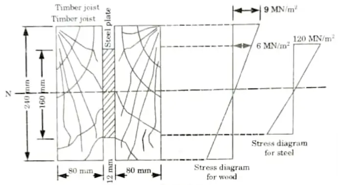
a. A flitched timber consists of two joints each 80 mm wide and 240 mm deep, with a steel plate 160 mm deep and 12 mm thick placed symmetrically between and clamped to them. Calculate the total moment of resistance of the section if the allowable stress in joist is 9 N/mm2. Take Es = 20 Et.
Ans. Given: Width of timber joist = 80 mm, Depth of timber joist 240 mm,
Thickness of steel plate = 12 mm, Depth of steel plate = 160 mm, Allowable
stress 9 N/mm2, Es = 20 Et.
To Find: Total moment of resistance of section.
1. Fig. shows the arrangement and also the stress distribution in timber and steel.
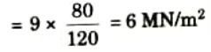
2. From the stress diagram, the stress in wood, at the level of steel is
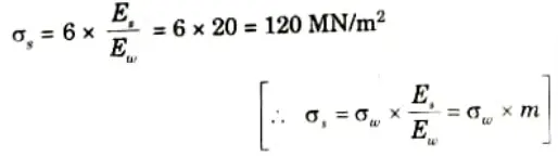
3. Since the strain in steel = Strain in wood, we have maximum stress in steel,
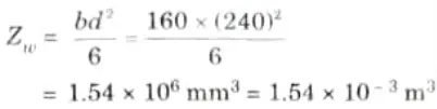
4. Now, section modulus for wood,
5. Section modulus for steel,

6. Moment of resistance of timber section,

7. Moment of resistance of steel section,

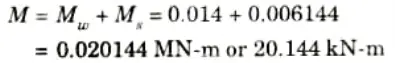
8. Total moment of resistance offered by the composite section,
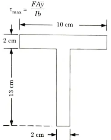
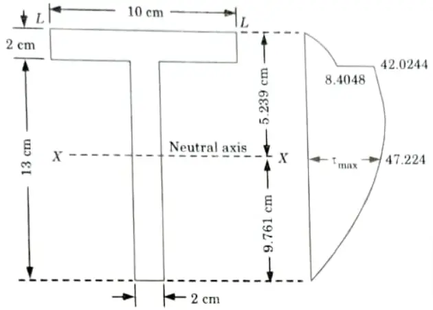
b. The T-section having flange of dimension 100 mm x 20 mm and web of dimension 20 mm x 130 mm is subjected to a shear force of 100 kN. Draw the shear stress distribution diagram and find the maximum shear stress.
Ans. Given: Width of flange 100 mm, Thickness of flange = 20 mm,
Thickness of web = 20 mm, Depth of web = 130 mm,
Shear force = 100 kN
To Find: i. Shear stress distribution diagram
ii. Maximum shear stress.
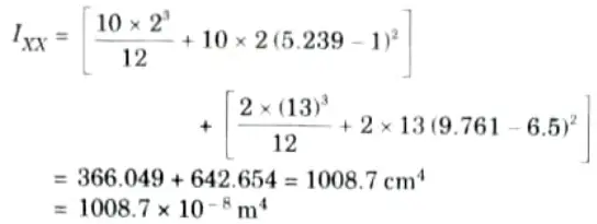
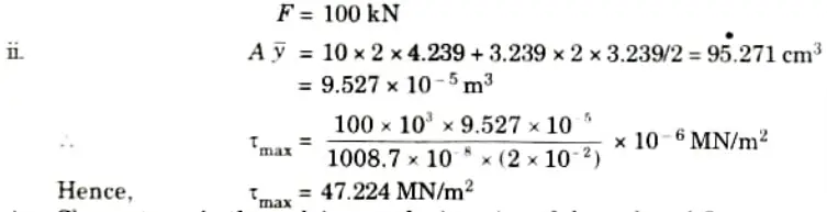
1. Let us first calculate the position of the neutral axis and moment of inertia of the section about the neutral axis.
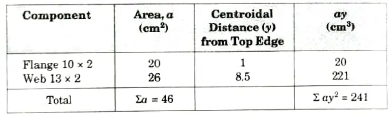
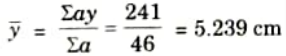
2. Distance of centroidal axis (neutral axis) from the top edge,
3. Maximum shear stress will occur at the neutral axis,
i. Maximum shear force,
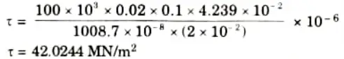
4. Shear stress in the web just at the junction of the web and flange.
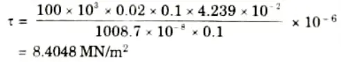
5. Shear stress in the flange just at the junction of the web and flange,
Section 5: Strength of Material Aktu Btech Notes
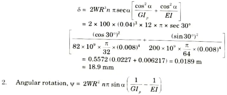
a. An open coiled helical spring made from wire of circular cross-section is required to carry a load of 100N. The wire diameter is 8 mm and the mean coil radius is 40 mm. If the helix angle of the spring is 30° and number of turns is 12, calculate (i) axial deflection (ii) angular rotation of free end. Take E = 200 GN/m2 and G= 82 GNm2.
Ans. Given: Diameter of wire, d = 8 mm = 0.008 m, Mean radius of coil,
R = 40 mm = 0.040 m, Helix angle, 𝛼 = 30°, Number of turns, n = 12
Axial load, W = 100 N, Modulus of rigidity, G = 82 GN/m2, Young’s
modulus, E = 200 GN/m2
To Find: i. Axial deflection
ii. Angular rotation of free end
1. Axial deflection in given by,
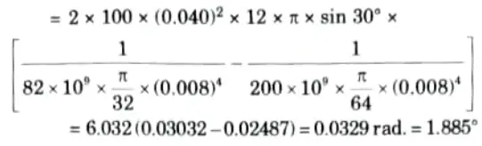
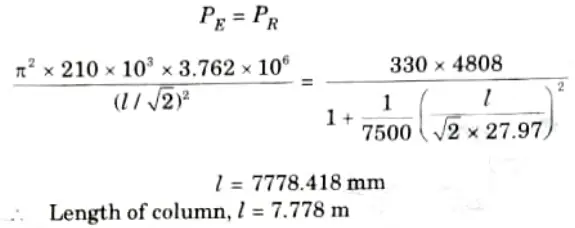
b. An I section 300 mm x 150 mm is provided with a flange plate 200 mm x 12 mm for each flange. The I section used as a strut with one end fixed and other end hinged. Calculate the length of the member for which the crippling load by Rankine and Euler formula will be same.
Take E = 2.1 x 10⁵ N/mm, 𝛔t = 330 N/mm2, 𝛂 = 1/7500.
Ans. Given: section = 300 mm x 150 mm, Flange plate = 200 mm x
12 mm, E =2.1x 10° N/mm”, 𝛔c =330 N/mm, 𝛂 = 1/7500
To Find: Length of the member
Data Assumed: Ixx = 73.329 x 106 mm4, Iyy = 3.762 x 106 mm4, A = 4808 mm2.
1. For one end fixed and other end hinged, effective length of column,
4. Rankine crippling load,
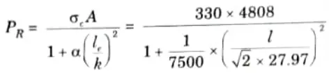
5. According to question, crippling load by Rankine and Euler formula are same. So, cquating eq. (3.26.1) and eq. (3.26.2), we get
Section 6: Aktu Quantum Notes Pdf Strength of Material
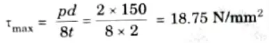
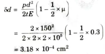
a. A cylindrical shell is 3 m long, 1.5 m internal diameter and 20 mm metal thickness. Calculate the intensity of maximum shear stress induced and the change in dimensions of the shell and change in volume of the shell if it is subjected to an internal pressure of 2 N/mm2. Take E = 2 x 10⁵ N/mm2 and 𝛍 = 0.3.
Ans. Given: Length of shell, L = 3 m = 300 cm, Internal diameter,
d = 1.5 m = 150 cm, Wall thickness, t = 20mm = 2 cm, Internal pressure,
P = 2 N/mm2, Young’s modulus, E = 2 x 10⁵ N/mm2, Poisson’s ratio, 𝛍 = 0.3
To Find: i. Intensity of maximum shear stress.
ii. Change in dimensions and volume of the shell.
1. Maximum shear stress is given by,
2. We know that,
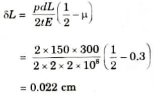
3. Change in length is given by
4. We know that,
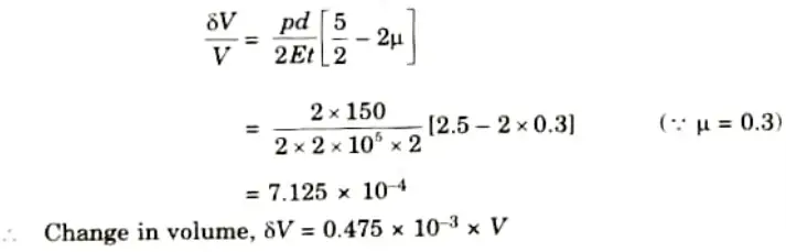
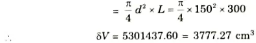
Where V = Original volume
b. Derive the Lame’s equations to find the stresses in thick cylinders subjected to internal pressure.
Ans. 1. The assumptions made in Lame’s theory are as follows:
a. The material is homogeneous and isotropic.
b. Plane sections perpendicular to the longitudinal axis of the cylinder remain plane after the application of internal pressure.
c. The material is stressed within elastic limit.
d. All the fibres of material are free to expand or contract independently without being constrained by adjacent fibres.
2 A thick cylinder subject to internal and external radial stress (pressure) is shown in Fig.
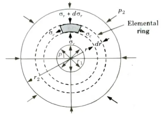
3. Consider an element ring of internal radius r and thickness dr.
4. Let,
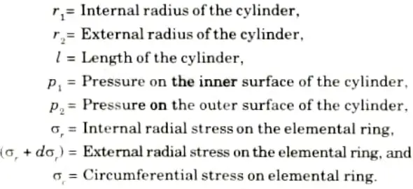
5. The conditions for equilibrium on one half of the elemental ring are (Similar to those in the case of thin cylinder) are as follows:
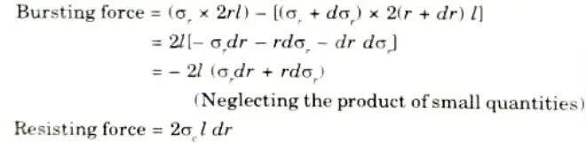
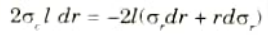
6. Equating the resisting force to bursting force (for equilibrium), we get

7. Now let us obtain another relation between the radial stress (pressure) and circumferential (or hoop) stress by using the condition that the longitudinal strain (𝜀l) at any point in the section is same.
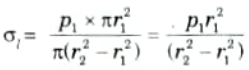
The Longitudinal stress,
8. Hence at any point in the section of the element ring considered above, the following three principal stresses exist,
a. The radial stress (pressure), 𝜎r,
b. The circumferential stress, 𝜎c
c. The longitudinal tensile stress, 𝜎l.
9. Since the longitudinal strain (𝜀l) is constant, we have
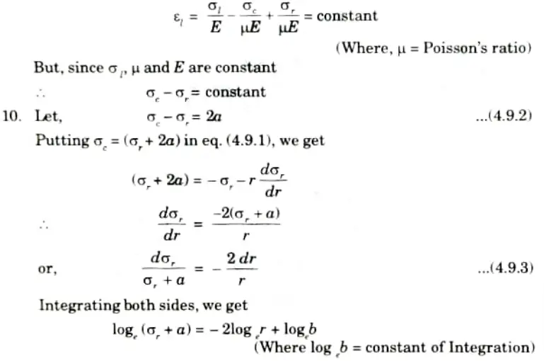
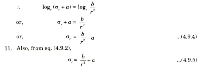
12. The eq. (4.9.4) and eq. (4.9.5) are called Lame’s equations.
13. The constant a and b can be evaluated from the known internal and external radial pressure and radius.
14. It may be noted that in the above equations 𝜎r is compressive and 𝜎e is tensile.
Section 7: Strength of Material Quantum book Pdf Aktu
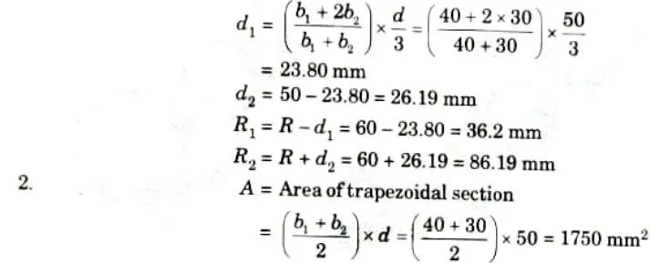
a. A curved beam of trapezoidal cross-section with widths as 40 mm and 30 mm, depth 50 mm is subjected to pure bending moment of 1500 Nm which try to increase the curvature. Find the bending stress at outermost and innermost fibres. Also plot the variation of bending stresses across the section.
Ans. Given: b1 = 40 mm, b2 = 30 mm, D 50 mm, Bending moment m = 1500 N-m
To Find: Bending stress at outermost and innermost fibre. 1. The distance ‘d1’ of centroidal axis from the side b1 is given by,
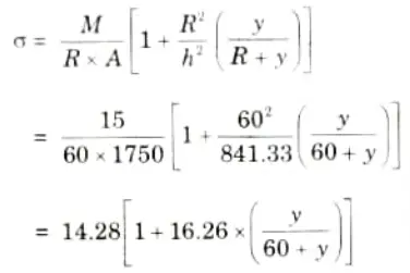
3. We know that
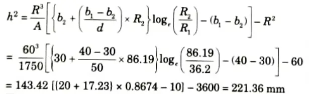
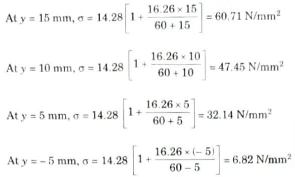
4. The stress at any layer at a distance ‘y’ from centroidal axis is given by
5. The stress will be maximum at the extreme bottom layer where
y = – 23.80 mm
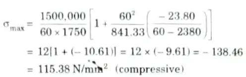
6. Minimum stress occurs at the extreme top layer where
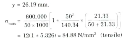
Plotting the stresses across the section
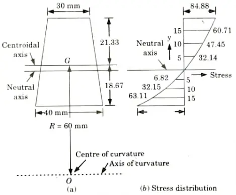
At y = 26. 19 mm, 𝜎 = 84.88 N/mm2 (Already calculated)
b. I section carries 40 kNm bending moment inclined at 18° to the x-axis determine the position of neutral axis from the x axis and the maximum bending stress acting on the section.
Ixx = 48.9 x 106 mm4, Iyy = 4.73 x 106 mm4
Zxx = 379 x 103 mm3, Zyy = 64.7 x 103 mm3
Ans. Given: M = 40 kNm, 𝜃 = 18°
Ixx = 48.9 x 106 mm4, Iyy = 4.73 x 106 mm4
Zxx = 379 x 103 mm3, Zyy = 64.7 x 103 mm3
To Find: i. Position of neutral axis.
ii. Maximum bending stress.
i. The position of neutral axis:
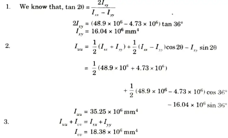
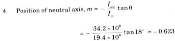
ii. Maximum Bending Stress:
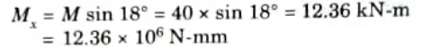
1. Bending moment
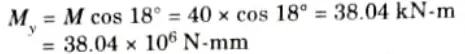
(To induce tensile stress in lower half)
2. As both the components of bending moment (i.e. , Mx and My) are give tensile stress in the 3rd quadrant, x and y both can be assumed positive in this quadrants. So the sign convention can be followed as shown in Fig.
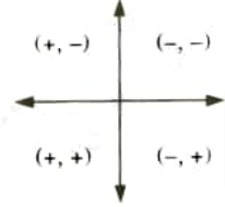
3. This shows that the maximum tensile stress will occur at A as both (x, y) co-ordinates for this quadrant are positive.
Position coordinate of A (x, y)
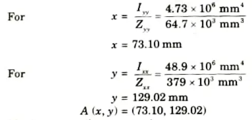
4. Maximum tensile stress at A,
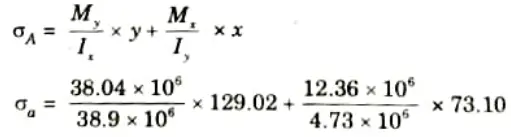
= 100.36 + 191.01
= 291.37 MPa
5 thoughts on “Aktu Question Paper Strength of Material Quantum Notes, Pdf List, Solutions, books”