Aktu Btech Quantum Notes will help you better understand Power System-I. Your exam preparation will benefit from these crucial, often asked questions. Boost your performance right away! Unit-4 Transmission Line Parameters
Dudes 🤔.. You want more useful details regarding this subject. Please keep in mind this as well.

Important Questions For Power System-I:
*Quantum               *B.tech-Syllabus
*Circulars                *B.tech AKTU RESULT
* Btech 3rd Year    * Aktu Solved Question Paper
Q1. Explain the factors, which are considered during designing a transmission line. Also explain how ground wire selection is done ?
Ans.
- 1. Choice for transmission voltage: The line voltage affects the performance of line and its cost. For getting the optimum operation transmission voltage, we may use following empirical formula
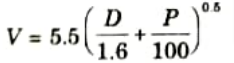
Here V = Operating line voltage in kV
D = Distance of transmission in km
P = Power handled in kW
For the specified line, a standard voltage is chosen that is closer to the value determined using the technique above. The fundamental estimate is provided by the formula. It is possible to get the most economical voltage by taking into account a variety of technical and financial factors.
- 2. Conductor size selection: The size of conductors should be carefully chosen throughout the design process since it affects the price of towers and foundations, which accounts for 30 to 45% of the line’s overall cost. The size of conductor chosen affects line losses as well. ACSR conductors, which come in a range of sizes, are typically employed.
- 3. Choice of span and conductor configuration: Few towers will be needed, but they will be more expensive and taller if the line span is lengthy. In order to lower the expensive cost of insulators, higher operating voltage is used on longer line spans.
- 4. Number of circuits: Either a single circuit or a double circuit may make up a transmission line. High power can be carried across double circuit lines with more dependability than single circuit lines.
- 5. Ground wire selection: Ground wire shields the phase conductors from lightning strikes. The ground wire is positioned above the conductors for the phases. Because it is grounded at each tower or alternate tower, lightning current is deflected to the ground.
The ground wire must be built to safely handle the highest anticipated lightning current without overheating. For the ground wire to not be overheated by the highest lightning current, it must have sufficient mechanical strength. Mechanical strength determines ground wire size, and galvanized steel is typically the material utilized.
- 6. Insulation design: The design of the insulation has a significant impact on line performance. Switching overvoltage that is both transitory and atmospheric should be handled by it.
Q2. Deduce an expression for the total inductance of a single phase line.
Ans.
- 1. First conductor carries current. Second conductor is return circuit of other. Both conductors are solid round conductor having radii r1 and r2.
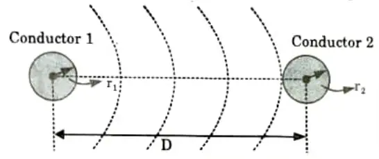
where, r1‘= Geometric mean radius (GMR) of conductor
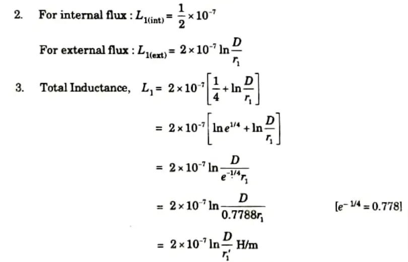
4. Similarly, inductance due to current in second conductor
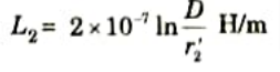

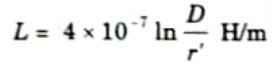
Total inductance of single-phase circuit is given by
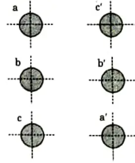
Q3. Find the inductance per phase per km of double circuit 3-phase line system shown in Fig. The conductors are transposed and are of radius 0.75 cm each. The phase sequence is abc.
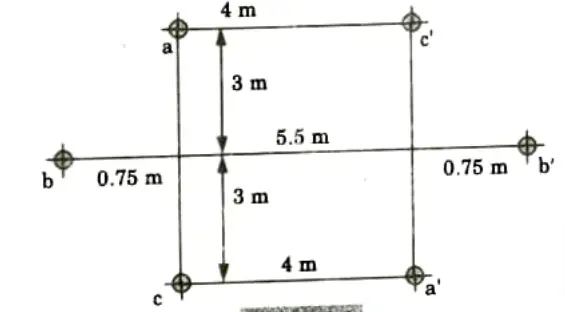
Ans. Given: Radius= 0.75 cm
To Find: Inductance per phase per km.
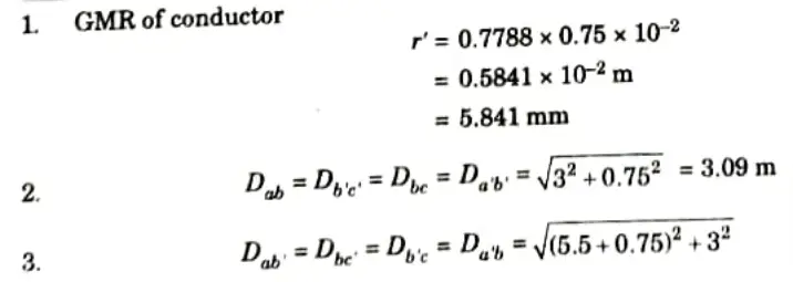
5. From symmetry, the self GMD of conductors of phase A and phase C must be equal.
6. Now, net self GMD of the circuit
7. Again from symmetry, the mutual GMD between phase A and B mi st be equal to the GMD between B and C.
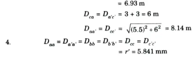
Mutual GMD between phase A and C
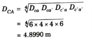
8. Net mutual GMD, Dm
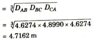
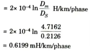
9. Inductance per phase per km
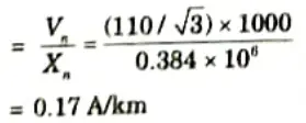
Q4. A 3-phase, 50 Hz transmission line has flat horizontal configuration with 3.5 m between adjacent conductors. The conductors are hard drawn 7 strand copper wire (outside conductor diameter = 1.05 cm). The voltage of the line is 110 kV. Find the capacitance to neutral and charging current per km.
Ans.
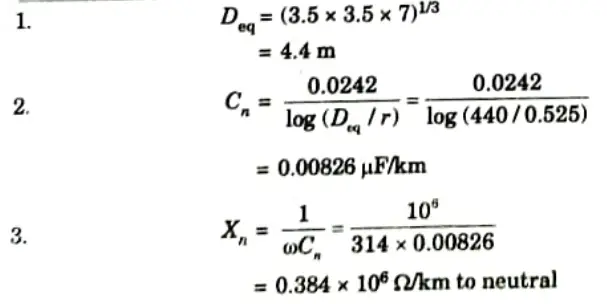
4. Charging current
Q5. What is the effect of earth on line capacitance? Explain the method of images to calculate the capacitance of two wire single phase line.
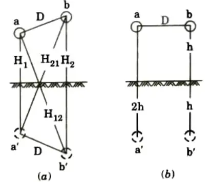
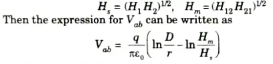
Ans. 1. Fig.(a) shows a two-wire single-phase line having conductors a and b. The spacing between the conductors is D. a’ and b’ are images of and b respectively. The charges on a and b are + q and – q respectively.
2. The potential difference between a and b can be written as
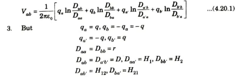
4. Substituting these values in eq. (4.20.1), we get
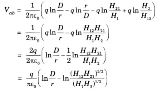
5. Mean distances
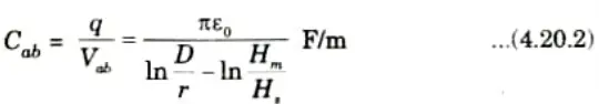
6. The line-to-line capacitance
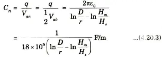
7. Line-to-neutral capacitance
Special Case:
i. When the conductors a and b are at the same height h from the ground as shown in Fig.(b).
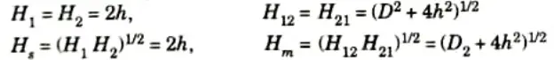
Eq. (4.20.3) shows that there is a slight increase in capacitance of the ine due o presence of earth.
ii. The effect diminishes as the height of the conductor above the earth is increased. It is not possible to caleulate the capacitance accurately.
Q6. Discuss the concept of self GMD and mutual GMD with the help of suitable example.
Ans. A. Self-GMD (Ds):
- 1. It is also called geometrical mean radius (GMR).
- 2. Inductance per conductor per meter length is given by,
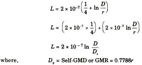
Sometimes GMR is denoted by r’.
- 3. A conductor’s self-GMD is depending on its size, form, and is unaffected by the distance between other conductors.
B. Mutual-GMD (Dm):
1. The geometric mean of the separation between two conductors is known as the mutual-GMD. It merely displays the corresponding geometric spacing.
Example :
1. The conductor arrangement of the double circuit is shown in Fig. Let the radius of each conductor be r.
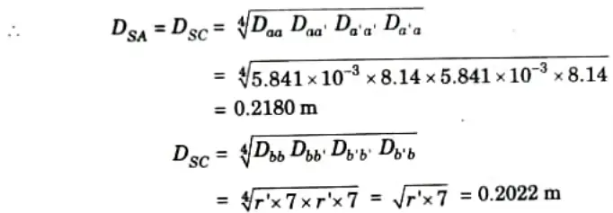
2. Self-GMD of conductor = 0.7788r
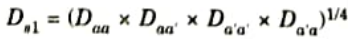
3. Self-GMD of combination aa’,
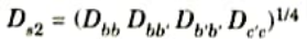
4. Self-GMD of combination bb’,
5. Self-GMD of combination c’,
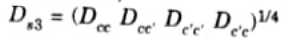
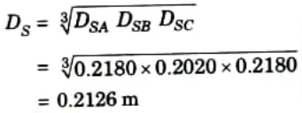
6. Equivalent self-GMD of one phase,
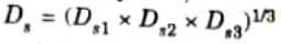
7. Since each conductor has the same radius, therefore the value of Ds is same for the all phases.
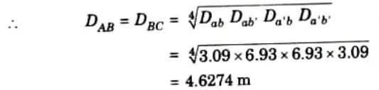
8. Mutual-GMD between phases A and B,
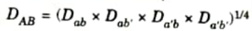
Mutual-GMD Between phases B and C,
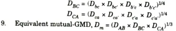
10. The conductor’s precise dimensions, shape, and orientation are irrelevant to mutual-GMD, which solely depends on the spacing.

Power System-I Btech Quantum PDF, Syllabus, Important Questions
| Label | Link |
|---|---|
| Subject Syllabus | Syllabus |
| Short Questions | Short-question |
| Question paper – 2021-22 | 2021-22 |
Power System-I Quantum PDF | AKTU Quantum PDF:
| Quantum Series | Links |
| Quantum -2022-23 | 2022-23 |
AKTU Important Links | Btech Syllabus
| Link Name | Links |
|---|---|
| Btech AKTU Circulars | Links |
| Btech AKTU Syllabus | Links |
| Btech AKTU Student Dashboard | Student Dashboard |
| AKTU RESULT (One VIew) | Student Result |