Use our AKTU question paper and solution to investigate the foundations of Power System – I. To fully understand the complexities of electrical power transmission and distribution, go into detailed PDFs and quantum notes.
Dudes 🤔.. You want more useful details regarding this subject. Please keep in mind this as well.

Important Questions For Power System - I:
*Quantum          *B.tech-Syllabus
*Circulars           *B.tech AKTU RESULT
* Btech 3rd Year
Section A: Power System – I Important Aktu Short Questions
a. What is demand factor ? Why is it important ?
Ans. A. Demand factor: The demand factor is the ratio of the system’s real maximum demand to its overall connected load.
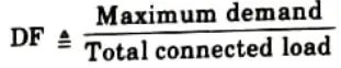
B. Reason: It is important in determining the capacity of the plant equipment.
b. For the same maximum demand, if load factor is decreased, then what will be the cost of energy?
Ans. It will increase.
c. What are the limitations of Kelvin law ?
Ans.
- i. Because of variations in load, load factors, and future load conditions, which are challenging to predict properly, the total amount of energy losses cannot be determined with accuracy.
- ii. Due to the fluctuating costs of conductor materials and interest rates, it is challenging to estimate the cost of energy loss.
- iii. Two systems with the same energy demand may incur varying costs because of varying energy costs.
- iv. Voltage drop may occasionally exceed allowable limits if an economical conductor size is chosen.
- v. Due to its thermal rating and temperature rise constraints, the most affordable size of conductor might not be able to carry the needed amount of current.
- vi. The mechanical strength of the economical part might not be sufficient.
- vii. The employment of inexpensive sections at extremely high voltage is opposed by corona, leakage current, skin effect, and other issues.
d. What is Ferranti effect?
Ans. The Ferranti effect is a phenomenon that causes a voltage increase at the line’s receiving end when it is open-circuited or lightly loaded..
e. How are voltage distribution and the string efficiency affected by rain?
Ans. Insulators become moist during the rainy season, increasing the mutual capacitance value. As a result, k, the ratio of shunt to mutual capacitance, drops. This makes the voltage distribution more uniform. Hence, string efficiency is higher during the rainy season.
f. What is the importance of sag in transmission line?
Ans. It safeguards the conductor from too much strain. Rather than being fully stretched, conductors are allowed to have sagged in order to provide for an acceptable degree of strain.g. Differentiate between GMD and GMR.
Ans.
| S. No. | GMD | GMR |
| 1. | The Geometrical Mean of the separations between the strands of two transmission lines is what we use in GMD. | For a single composite conductor, the Geometrical Mean of the distances between the stands is computed. |
h. Why the effect of ground on the line capacitance can be neglected?
Ans. Smaller lengths and lower voltage result in smaller capacitance effects, which can be disregarded.
i. Why single core cables are usually not provided with armouring ?
Ans. To reduce excessive sheath losses, single-core cables are typically not armored.
j. How do voids in the insulation cause breakdown of the cable?
Ans. Because the void has a lower permittivity than the insulation and a lower breakdown strength, the void’s existence causes insulation breakdown.
Section B: Power System – I Quantum Pdf Notes
a. What are the conventional and non conventional sources of energy ? Explain with examples.
Ans. A. Conventional energy sources: The traditional energy sources are typically non-renewable energy sources. Certain energy sources, such as coal, petroleum, natural gas, etc., are exhaustible, meaning they cannot be replaced after being used up.
B. Non-conventional energy sources: Renewable energy sources typically make up non-traditional energy sources. Inexhaustible energy sources, such as solar, wind, and others, are those that can continually produce energy.
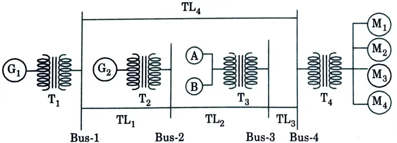
b. Draw single line diagram of a four-bus system having generator G1 connected to bus-1 through transformer T1 generator G2 connected to bus-2 through transformer T2 load A and load B connected to bus-3 through transformer T3 four synchronous motors M1 to M4 connected to bus-4 through transformer T4 transmission lines TL1, TL2, TL3 and TL4 connected between bus 1-2, 2-3, 3-4 and 4-1 respectively.
Ans.
c. What are the main characteristics of an ideal insulator ? Describe the main advantages and disadvantages of glass insulators. Explain rating and string efficiency of an insulator.
Ans. A. Characteristics of insulator:
- 1. In order to support the weight of the conductors, they need to be mechanically very strong.
- 2. Very high dielectric strength is required.
- 3. They need to have a high pierce strength to voltage ratio in order to flash.
- 4. They must not be permeable.
- 5. They must be devoid of internal fluxes or contaminants.
- 6. They must be resistant to liquids or gases penetrating the materials.
- 7. Temperature fluctuations shouldn’t have an impact on them.
B. Advantages and disadvantages of glass insulator:
a. Advantages:
- 1. The glass disc insulator has a high dielectric strength in comparison to ceramic materials.
- 2. The glass disc insulator has a low coefficient of thermal expansion and a very high resistance.
- 3. It has a higher tensile strength than porcelain insulators.
b. Disadvantages:
- 1. Because it is simple for moisture to condense on glass, air dust will be deposited on the wedge-shaped glass surface, creating a path for the system’s leakage current.
- 2. Glass cannot be formed in irregular forms at higher voltages because the uneven cooling results in internal cooling and internal strain.
C. Rating:
| Insulator | Voltage capacity |
| Pin insulator | < 11 kV |
| Suspension insulator | 11 kV to 765 kV |
| Strain insulator | > 33 kV |
| Shackle insulator | <33 kV |
D. String efficiency: String efficiency is measure of the utilization of material in the string and is defined as :

where n is number of disc or insulator.
d. Derive expressions for the line-to-neutral capacitance and line-to-line capacitance of a single phase line.
Ans. A. Expression for potential difference:
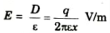
1. From Gauss’s law, electric field density (D) at a point distance x meters from a conductor having charge q is,
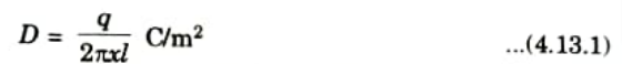
(Taking length of conductor = 1 m)
2. Electric field intensity at distance x,
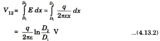
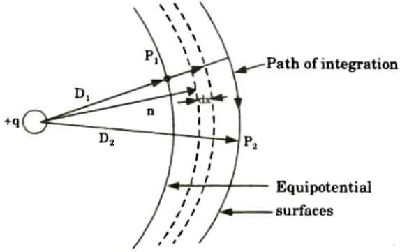
3. Voltage between P1 and P2.
B. Capacitance of single phase line:
1. Potential due to qa using eq. (4.13.2)
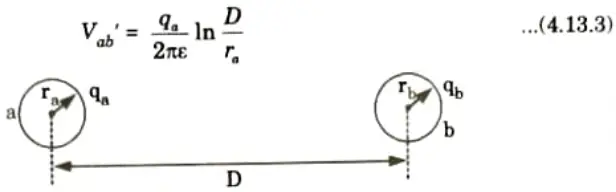
2. Potential due to qb using eq. (4.13.2)

3. Net potential from a to b,
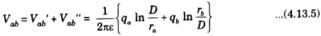
4. Since b is return conductor,
qa = – qb
5. On putting qa = – qb eq. (4.13.5) becomes
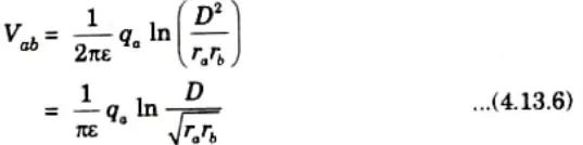
6. Now capacitance of line,
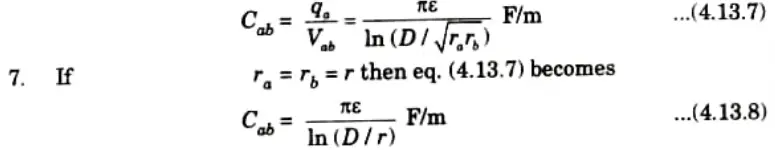
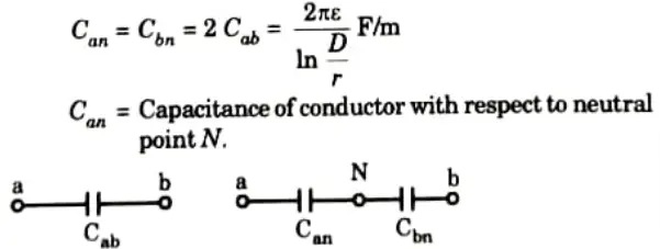
8. Half of the potential difference between the two conductors exists between each conductor and neutral. This indicates that the capacitance of a conductor relative to the neutral point will be two times greater than that of a single phase line.
e. Discuss the inter-sheath grading of cables. What are practical difficulties in the grading of cable ?
Ans. A. Inter-sheath grading:
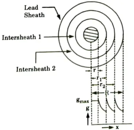
- 1. A homogenous dielectric is employed in intersheath grading, but it is separated into several layers by sandwiching metallic intersheaths between the core and lead sheath. Between the core potential and the earth potential, the intersheaths are maintained at acceptable potentials.
- 2. Consider a cable of core radius r and outer lead sheath of radius R. Suppose that two intersheaths of radius r1 and r2 are inserted into the homogeneous dielectric and maintained at some fixed potentials. V1, V2 and V3 respectively be the voltage between core and intersheath 1, between intersheath 1 and 2 and between intersheath 2 and outer sheath.
- 3. Since each intersheath has a distinct potential difference between its inner and outer layers, each sheath can be thought of as a uniform single core cable.
- 4. Maximum stress between core and the intersheath 1 is,
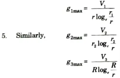
6. The dielectric is homogeneous, the maximum stress in each layer is the
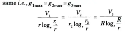
7. As the cable behaves like three capacitors in series, therefore, all the potentials are in phase i.e., voltage between conductor and earthed lead sheath is
V = V1 + V2 + V3
B. Difficulties: Since they are so thin, the intersheath layers used in intersheath grading are susceptible to damage while being transported or installed.
Section 3: Power System – I Important Long Questions
a. A generating station has a maximum demand of 35 MW, a load factor of 50 %, a plant capacity factor of 80 % and a plant use factor of 62 %. Find (i) the reserve capacity of the plant (ii) the daily energy produced and (iii) Maximum energy that could be produced daily if the plant while running as per schedule, were fully loaded.
Ans. Given: Maximum demand 35 MW, load factor= 50 %, plant capacity factor 80 %, plant use factor 62%
To Find: Reserve capacity, daily energy produced, maximum energy that could be produced daily.
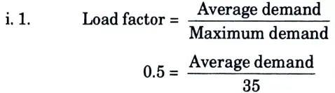
2. Average demand
= 35 x 0.50 = 17.5 MW
3. Plant capacity factor
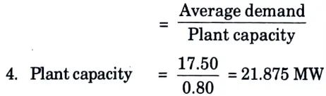
5. Reserve capacity of plant = Plant capacity – Maximum demand
= 21.875 – 35
= -13.12 MW
ii. Daily energy produced = Average demand x 24
= 17.5 x 24 = 420 MWh
iii. Maximum energy that could be produced
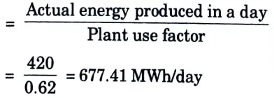
b. Define and explain the importance of the following terms in generation: (i) Connected load (ii) Maximum demand (iii) Diversity factor (iv) Average load.
Ans. i. Connected load: The total continuous ratings of all connected loads make up the connected load.
ii. Maximum demand: The highest demand that has ever been placed on a system or installation is one that has taken place during a particular time frame.
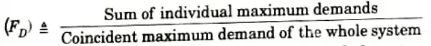
iii. Diversity factor: The diversity factor is the ratio of the total maximum demands of all system subdivisions to the total maximum demand.
Diversity factor
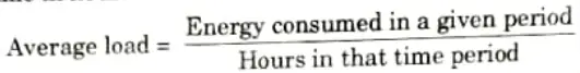
iv. Average load: It is the ratio of energy used over a specific amount of time expressed in hours.
Section 4: Skin Effect and Proximity Effect Aktu Repeated Questions
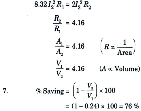
a. Explain difference between skin effect and proximity effect. What is the percentage saving in copper feeder if the line voltage in a 2-wire DC system is raised from 220 V to 450 V for the same power transmitted over the same distance and having the same power loss ?
Ans. A. Difference:
| S. No. | Skin effect | Proximity effect |
| 1. | Alternating current is dispersed unevenly throughout the conductor’s cross section as it travels through it. Because of this, the current density at the conductor’s surface is greater than the current density at its centre. Skin effect is the term for this effect. | The magnetic fields of two or more conductors interact when they are close to one another, causing currents to circulate inside the conductor. The proximity effect is the name of this effect. |
| 2. | Skin effect increases effective resistance of conductor. | The conductor’s resistance increases as a result of the proximity effect in transmission lines. |
| 3. | The frequency and wire diameter have an impact on the skin effect in transmission lines. | It is based on the material’s resistivity and the distance between conductors. |
B. Numerical:
1. Power, P = VI
2. Power in 220 V system
P1 = 220 I1
3. Power in 450 V system
P2 = 450 I2
4. As given, P1 = P2
220 I1 = 450 I2
I1 = 2.04 I2
5. Now power loss,
W = 2I2R
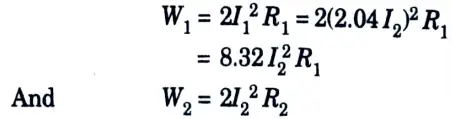
6. As given, W1 = W2
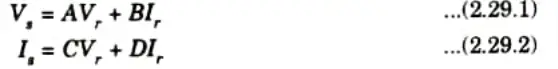
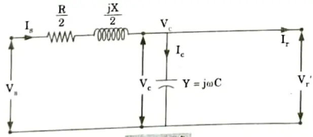
b. Derive the A, B, C, D constants for the transmission line represented by nominal T section and draw its phasor diagram.
Ans. The steady-state voltage at the sending and receiving ends are expressed in terms of voltage and current at the receiving end
Nominal T method:
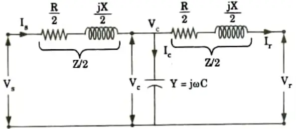
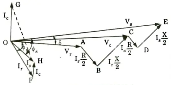
1. From Fig. 2.29.1,
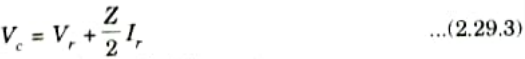
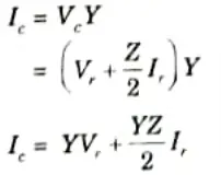
2. The current through the shunt admittance is
3. Now the sending-end current is
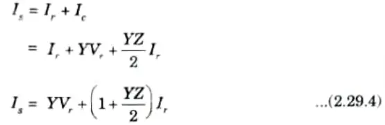
and the sending-end voltage is
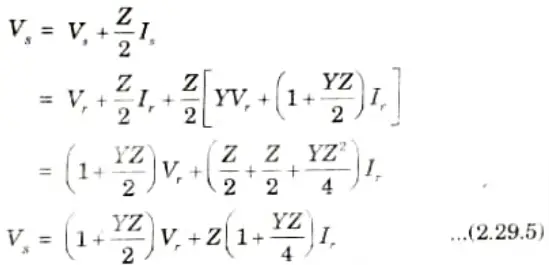
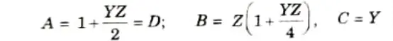
4. For general transmission circuit constants, comparing the eq. (2.29.4) and eq. (2.29.5) with eq. (2.29.1) and eq. (2.29.2) respectively, we get
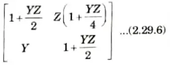
5. The transfer matrix for the network is
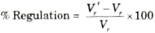
Regulation:
1. Under no load condition, the equivalent circuit of Fig. 2.29.1 is shown in Fig. 2.29.3.
2. At no load, the voltage at the receiving end (Vr’) of the transmission line is same as the voltage (Vc) across the admittance, which is located at midpoint of the transmission line.
3. From Fig. 2.29.3, the voltage across the capacitor by using voltage divider rule is
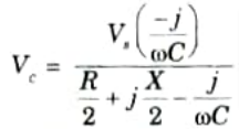
When the receiving end is on no load, the no-load voltage, Vr’ =Vc
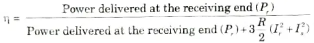
Efficiency:
Section 5: Power System – I Quantum Pdf Aktu Notes
a. What do you understand by vibration dampers in overhead transmission line ? Describe the different types of dampers used.
Ans. A. Vibrations:
- 1. At each tower, the conductors are supported by string insulators.
- 2. The conductor may begin vibrating mechanically in the vertical plane in a wide range of climatic circumstances, such as strong wind speeds. These vibrations can occur in a variety of frequencies, amplitudes, and modes.
Types of vibrations in the vertical plane:
a. Aeoline vibrations:
- 1. The amplitudes of the aeoline vibrations range from 2 to 5 cm, with a frequency range of 5 to 50 Hz.
- 2. As a result, these vibrations have a high frequency but a low amplitude.
- 3. Wind speeds between 2 and 40 kmph can produce this kind of vibration.
Minimization of aeoline vibration: The effect of aeoline vibration can be minimized by,
- 1. Use of bundle conductor
- 2. Proper design and location of spacers
- 3. Use of damper
- 4. Use of clamps.
b. Galloping of conductor/dancing of conductor:
- 1. The galloping means dancing of conductors at the low frequency and high amplitude.
- 2. These are the oscillations of complete span of conductors.
- 3. The frequencies of galloping are about 0.5 to 2 Hz with the amplitude of about 6 m.
Minimization of galloping of conductor:
There is no way to stop galloping, but under icing situations, the height of the conductors can be correctly constructed with the amplitude of any potential galloping in mind.
B. Vibration dampers: Vibration damper are the devices used to minimize the vibrations in the conductors. The following two devices are used to prevent vibration in conductors:
a. Armour rods:
- 1. Armour rods have tapered ends and are made up of spiral layers of little round rods.
- 2. Because to their significantly wider diameter than the actual conductor, they offer resistance to bending at the suspension point, thereby lowering the vibration’s amplitude by dispersing loads at the support point.
- 3. They also offer superior defence against flashover.
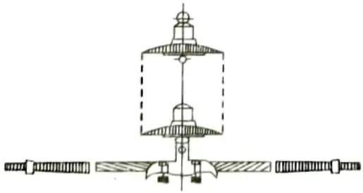
b. Stockbridge damper:
- 1. It is a piece of equipment that catches vibrational energy. With a clamp in the centre to secure it to wires, it is made up of two hollow weights connected by a flexible steel wire.
- 2. Each place where conductors are suspended needs two dampers one on each side. There are two dampers on each conductor span, though there may be more dampers on larger spans.
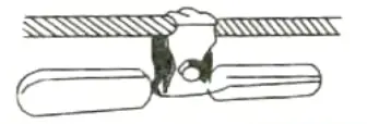
b. An overhead line at a river crossing is supported from two towers of heights 30 meters and 90 meters above water level with a span of 300 meters. The weight of the conductor is 1 kg/meter and the working tension is 2000 kg. Determine the clearance between the conductor and the water level midway between the towers.
Ans. Given: The working tension, T 2000 kg, Span, L= 300 m, weight of the conductor, w = 1kg/m, h1 =30 m, h2 = 90 m
To Find: Clearance between the conductor and the water level midway between the towers.
1. The difference in height of tower,
h = 90 – 30 = 60 m
2. Distance between the shorter support and lower point on conductor,

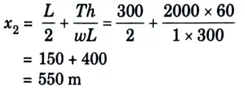
3. Distance between the longer support and lower point on conductor,
4. Sag with respect to the lower support,
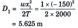
5. Clearance between the water level and the lower point of the conductor
= 30 – 5.625 = 24.37 m
6. Distance from the midpoint between the two towers and the lower point of the conductor,
x = 150 + 150
x = 300 m
7. Sag at the midpoint of the supports,
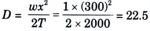
8. Clearance between the water and conductor at midpoint between two conductors
= 24.37+ 22.5
= 46.87 m
Section 6: Power System – I Important Numerical
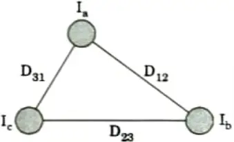
a. Starting from first principles, derive the expression for inductance of a 3-phase unsymmetrical spaced transposed transmission line.
Ans. i. Inductance of a three phase transmission with unsymmetrical spacing:
1. Consider a single circuit 30 system as shown in Fig. The three conductors are unsymmetrically placed ie., D12 ≠ D23 ≠ D31 and each conductor has a radius of r meters.
2. The flux linkage of conductor a due to Ia, Ib, and Ic.
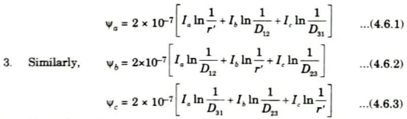
4. Now taking Ia as a reference phasor of unbalanced three phase system
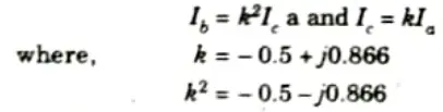
5. Substituting the values of Ib and Ic in the eq. (4.6.1), we get
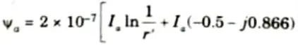
7. Significance of imaginary term in expression of inductance: A complex number represents the individual phase inductance of an untransposed line with an asymmetrical spacing. Flux-linkage or inductance’s fictitious component symbolises the transfer of energy between phases.
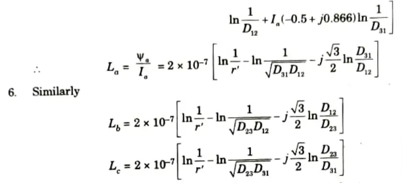
8. For transposed line, average value of inductance
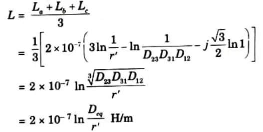
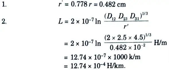
b. The three conductors of a 3-phase line are arranged at the corners of a triangle of sides 2 m, 2.5 m and 4.5 m. Calculate the inductance per km of the line when the conductors are regularly transposed. The diameter of each conductor is 1.24 cm.
Ans. Given:

To Find: L
Section 7: Power System – I Question Paper Pdf with Aktu Notes
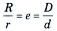
a. Show that the most economical size of conductor in a single core cable is obtained when radius of cable sheath (R) equals e.r. where e is the base of radius of conductor. Explain dielectric loss.
Ans. A. Most economical size of conductor:
1. The value of gmax will be minimum when
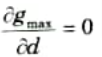
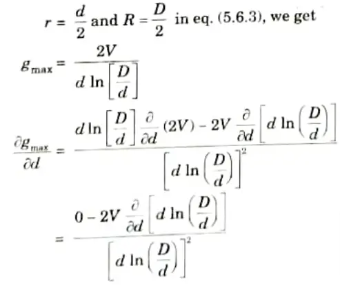
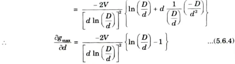
3. Now the value of

must be zero to get minimum gmax.
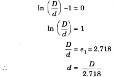
4. Hence, the core diameter must be 1/2.718 times the sheath diameter D so as to give the minimum value of gmax.
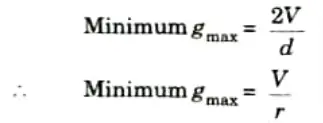
5. The value of minimum gmax is,
B. Dielectric loss:
1. Between a conductor and sheath, with a dielectric medium in between, there is capacitance. The symbol for this is C. R stands for leakage resistance.
2. The equivalent circuit of the cable is a parallel combination of R and C. So there are two currents one perpendicular to voltage V which is leading capacitive current Ic while other is in phase with voltage V which is resistive current Id representing dielectric loss.
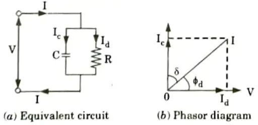
3. The dielectric loss is loss due to leakage resistance given by
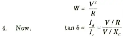
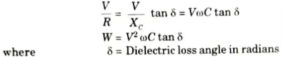
5. Generally 𝛿 is very small and hence tan 𝛿 ≃ 𝛿 for low voltage cables dielectric loss can be neglected as it is small but for high voltage cables it must be considered.
b. Find the most economical diameter of a single core cable to be used on 66 kV, 3 phase system. If the peak permissible stress is not to exceed 50 kV/m. Also find overall diameter.
Ans. 1. RMS value of phase voltage
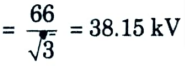
2. Peak value
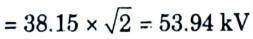
3. For economical size of cable,
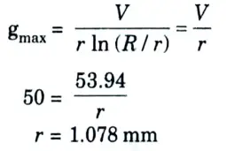
4. Economical diameter, d = 2 x r
2 x 1.078 = 2.157 mm
5. Overall diameter, D = e x d
= 2.71 x 2.157
= 5.845 mm
6 thoughts on “Power System – I: Quantum Pdf Aktu Solved Question Paper Notes”