Aktu Btech Quantum Notes will help you better understand Power System-I. These critical, commonly asked questions can help you prepare for your exam. Boost your performance right now! Unit-2 Transmission and Distribution of Electric Power-I
Dudes 🤔.. You want more useful details regarding this subject. Please keep in mind this as well.

Important Questions For Power System-I:
*Quantum               *B.tech-Syllabus
*Circulars                *B.tech AKTU RESULT
* Btech 3rd Year    * Aktu Solved Question Paper
Q1. Discuss choice of transmission voltage in power system.
Ans. While selecting an optimum transmission voltage following two factors are to be considered:
- 1. Power to be transmitted: Large generating and transforming units are needed to transport huge amounts of electricity, which lowers the cost per kW of terminal station equipment.
- 2. Distance of transmission line: Long-distance transmission of power lowers the cost of terminal equipment, which lowers the overall cost of transmission.
- 3. Above two terms can be related in an empirical formula which is as follows:
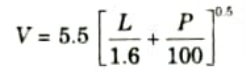
where, V = Line voltage in kV
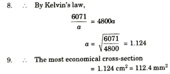
L = Distance of line in km
P = Power to be transmitted in kW
A standard voltage nearest to this calculated value should be selected.
- 4. Following are voltages which are generally adopted :
Generation = 6.6 kV, 11kV
Primary transmission = 132 kV, 220 kV, 400 kV
Secondary transmission = 11 kv, 22 kV, 33 kV
Primary distribution = 11 kV, 22 kV, 33 kV
Secondary distribution = 440 V
Q2. Explain different types of conductors in power system.
Ans. Conductors which are generally used for transmission lines are:
A. Hard-Drawn Copper Conductor:
- 1. Voltages up to 33 kV are mainly employed for short lines. It has a long lifespan and good electrical conductivity.
- 2. It works best for distribution tasks involving many tappings. The tensile strength of hard drawn copper is very strong.
B. Aluminium Conductor Steel Reinforced (ACSR):
- 1. ACSR is utilised for high voltage lines with huge spans and heavy loads.
- 2. Due to its limited mechanical strength, aluminium alone cannot be used to build long span gearbox lines. Hence, in order to strengthen it, we add steel wire in the conductors made of aluminium.
C. Cadmium Copper Conductor:
- 1. The strength of copper can be improved by 50% by adding cadmium, but the conductivity is reduced by 15%.
- 2. Longer transmission line spans can be built with the same sag because to the high tensile strength.
- 3. Hilly places frequently employ this conductor.
D. Steel Cored Copper Conductor (SCC):
- 1. In SCC, copper strands are arranged in layers around a steel wire. The conductor’s tensile strength is increased by the steel core. Hence, the conductor’s overall strength rises.
- 2. To shield the conductor from galvanic activity, bituminized cotton tape is utilized between the steel core and copper strands.
E. Hard-Drawn Aluminium Conductor:
- 1. Aluminum is replacing copper in gearbox work due to the rising cost of copper. Aluminum has a larger cross section while weighing less for a given resistance.
- 2. As a result, handling, moving, and erecting aluminium conductor lines are affordable. Aluminium is electrolytically purified, rolled, and hard drawn before being used as a conductor.
- 3. These conductors are utilized in metropolitan settings with low-voltage, short transmission lines. Higher conductor diameter also reduces the corona effect.
F. Phosphor-Bronze Conductor:
- 1. Phosphor-Bronze Conductor has a lower conductivity than copper Conductor but is stronger. Using cadmium copper core will increase its conductivity.
- 2. It is typically employed as a conductor material where extremely large spans, like at river crossings, are necessary.
G. Galvanized Steel Conductor:
- 1. Especially in rural areas with little load, this conductor is used for very long spans. The tensile strength of these conductors is very high.
- 2. A magnetic material with high resistance, inductance, and voltage drop is galvanised steel conductor. It has a rather brief lifespan.
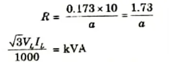
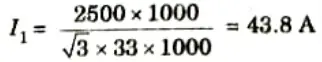
Q3. The daily-load cycle of a three-phase, 33 kV, 10 km transmission line is as follows : 2500 kVA for 8 hours, 2000 kVA for 9 hours and 1500 kVA for 7 hours. Determine the most economical cross section if the cost of line including erection is Rs. (7500) + 8000a) per km where a is the area of each conductor in sq. cm.The rate of interest and depreciation is 8 percent and cost of energy is 15 paise per unit. The line is in use for 250 working days a year. The resistance per km and per sq. cm. is 0.173 ohm.
Ans. Given: Cost of line = Rs. (7500+ 6000a10; VL = 33 kV
110 km; kVA = 2500 kVA for 8 hour, 2000 kVA for 9 hour,
1600 kVA for 7 hour; rate of interest aud depreciation = 8 %;
Cost of energy 15 paise per unit, working days in a year = 250,
Resistance per km and per sq. cm. = 0.173 ohm
To Find: Most economical cross section.
1. Cost of line = Rs. (7500 + 6000a) x 10
2. Annual interest and depreciation on capital cost
= Rs. (7500+ 6000m) x 10 x 8/100
= Rs. (6000 + 4800a)
3. Resistance of each conductor,
4. The load current at various loads are calculated by the above formula as follows:
At 2500 kVA, load current
At 2000 kVA, load current
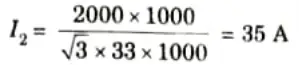
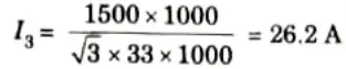
At 1500 kVA, load current
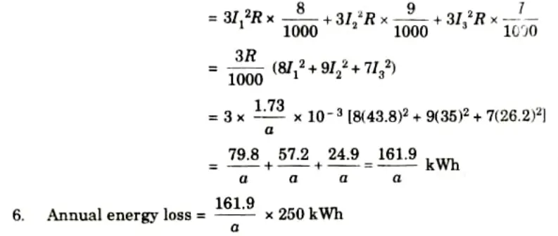
5. Daily energy loss
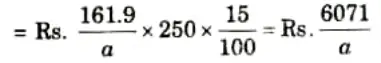
7. Cost of energy loss per annum
Q4. Determine the best current density in amperes/mm2 for a three phase overhead line. The line is in use for 3600 hours per year and ifthe conductor costs Rs. 3.0/kg. It has a specific resistance of 1.73 x 10⁻⁸ 𝜴-m and weights 6200 kg/m3 cost of energy is 12 paise/unit. Interest and depreciation is 10 % of conductor cost.
Ans. Given: Line in use = 3600 hours per year;
Conductor costs = Rs. 3 per kg; 𝝆 1.73 x 10⁻⁸ 𝜴-m
Weights= 5200 kg/m3; Cost of energy= 12 paise/unit.
To Find: Current density in amperes/mm2.
1. I = Length of each conductor
a = Area of cross section
2 Volume of conductor = la x 6200 kg
= 6200 x la kg
3. Capital cost of the conductor
= Rs. 3 x la x 6200
= Rs. 18600 x la
4. Interest ani depreciation
= Rs. 186 x la x 10
= Rs. 1860 x la
5. Cupper loss per conductor
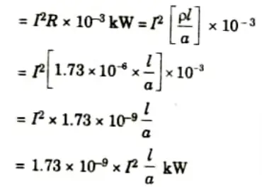
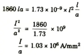
6 According to Kelvin’s law, the two costs should be equal for the best current density.
Q5. Discuss phenomenon of corona and how it is formed.
Ans. A. Corona: Corona is the term for the occurrence of a violet glow, hissing sound and ozone gas production in an overhead gearbox line.
B. Phenomenon of corona:
- 1. The ambient air around the conductors is exposed to electrostatic stresses when an alternating potential difference is applied between two conductors whose separation is wide compared to their diameters.
- 2. The ambient air surrounding the conductors remains unchanged at low voltage.
- 3. But as the potential difference gradually grows, a stage occurs where a violet-colored luminescent glow, a hissing sound, and ozone gas production arise.
- 4. If the potential difference is increased much further, the light and noise will get worse until a spark-over occurs because of a breakdown in the air insulation.
B. Theory of corona formation:
- 1. There are several free electrons in the air surrounding the conductor. When a potential difference is created between two conductors, a potential gradient is created, and as a result, the electrons experience a steadily increasing acceleration.
- 2. As a result, the liberated electrons pick up speed and collision with other neutral or slowly moving molecules, removing one electron from them in the process.
- 3. One or more electrons are dislodged from the potential gradient when it reaches a maximum value of roughly 30 kV per em due to the velocity attained by the free electrons.
- 4. By colliding with additional neutral molecules, these displaced electrons and the earlier released electrons produce more electrons. The insulating quality of air is lost when the saturation point is achieved; instead, the air turns into a conducting medium, and a corona emerges.
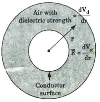
- 5. Corona occurs if
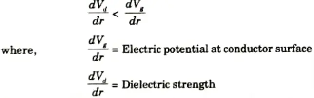
where r is a radial vector, perpendicular to conductor surface.
If potential gradient (dVg/dr) exceeds the dielectric strength (dVddr) the corona occurs.
Q6. Discuss electromagnetic interference with communication lines.
Ans.
- 1. When a power conductor with a strong magnetic field is put close to other conductors, it results in electromagnetic interference (EMI) (communication lines). The neighbouring conductors (communication lines) are severed by the flux lines of the intense magnetic field, which also induce voltage on them. The communication signal may be hampered by the presence of EMl.
- 2. Consider a three-phase overhead transmission system consisting of three conductors R, Y and B spaced at the corners of a triangle and two telephone conductors P and Q below the power line conductors running on the same supports as shown in Fig.
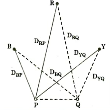
- 3. Let us assume that the radius of each conductor is r and consider the loop formed by the conductors R and P. Now the distances between R and P, and R and Q are DRP and DRQ, respectively.
- 4. Flux linkages of conductor P due to currents in all conductors of power line given by ;
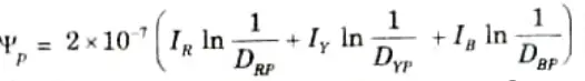
- 5. Flux linkages of conductor Q due to currents in all conductors of power line,
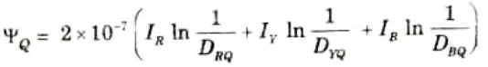
- 6. Total flux linkages of communication lines,
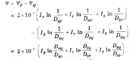
Therefore, the induced voltage in the communication line,
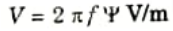
- 7. Here, the voltage induced and flux linkages of communication line depends upon the values of IR, IY, and IB.
Case-I: If the currents IR, IY, and IB are balanced and power lines are transposed, then flux linkages with the communication lines are zero. Therefore, voltage induced is also zero.
Case-II: If the currents IR, IY, and IB are balanced and power lines are untransposed, then flux linkages with the communication lines are small. Therefore, voltage induced is also small.
Case-III: If the currents IR, IY, and IB are unbalanced, then there is flux linkage with the communication lines and therefore, voltage is induced.
- 8. By moving the communication wires farther away from the power lines or even by transposing them, the induced voltage can be decreased.

Power System-I Btech Quantum PDF, Syllabus, Important Questions
| Label | Link |
|---|---|
| Subject Syllabus | Syllabus |
| Short Questions | Short-question |
| Question paper – 2021-22 | 2021-22 |
Power System-I Quantum PDF | AKTU Quantum PDF:
| Quantum Series | Links |
| Quantum -2022-23 | 2022-23 |
AKTU Important Links | Btech Syllabus
| Link Name | Links |
|---|---|
| Btech AKTU Circulars | Links |
| Btech AKTU Syllabus | Links |
| Btech AKTU Student Dashboard | Student Dashboard |
| AKTU RESULT (One VIew) | Student Result |