
With Aktu Btech Quantum Notes, you may increase your understanding of IC Engines, Fuel, and Lubrication. Utilise these essential, often asked questions to prepare for your tests. Improve your performance right now! Unit-3 Carburetion, Fuel Injection and Turbocharging
Dudes 🤔.. You want more useful details regarding this subject. Please keep in mind this as well.

Important Questions For IC Engine, Fuel and Lubrication:
*Quantum                 *B.tech-Syllabus
*Circulars                  *B.tech AKTU RESULT
* Btech 3rd Year      * Aktu Solved Question Paper
Q1. What are the mixture (air-fuel ratio) requirement for:
i. Maximum power,
ii. Maximum economy,
iii. No load,
iv. Normal load, and
v. Full load.
Ans. i. Mixture Requirement for Maximum Power:
- 1. The mixture (air + fuel) ratio required is 12:5:1 (richer).
- 2. Because all of the oxygen in the cylinder is used, the most energy is released when somewhat more fuel is used.
- 3. A richer mixture shouldn’t be used because it will lead to worse combustion and a lower output of energy.
ii. Mixture Requirement for Maximum Economy:
- 1. A little leaner mixture yields the best fuel economy since the presence of extra air guarantees that all the fuel is burned properly and efficiently.
- 2. Using more lean mixture than necessary can reduce the efficiency and cycle temperature.
iii. Mixture Requirement for No Load Condition or Idling Condition:
- 1. The rich mixture is required when there is idling or no load condition.
iv. Mixture Requirement for Normal Load (Economy Range):
- 1. In this range, the dilution caused by leftover gases and trapped air is reduced, and maintaining economy is the main focus.
- 2. So, slightly leaner air-fuel ratio is needed around 16:5:1.
v. Mixture Requirement for Full Load (Power Range):
- 1. Power range requires a rich composition. A rich mixture not only produces the most power possible but also loads the exhaust valve to minimize overheating and detonation.
Q2. Briefly explain with a neat sketch the operation of a simple float type carburetor.
Ans. A. Construction of Simple Float Type Carburetor:
- 1. Fig. depicts a basic float-type carburetor. It includes a venturi, a throttle valve, a nozzle with a metering aperture, and a float chamber with a needle valve.
- 2. The fuel level in the float chamber is kept constant.
- 3 As the fuel level in the float chamber falls below the desired level, the float descends and opens the valve needle to allow additional fuel from the fuel tank to be supplied.
- 4. The float moves upward and closes the valve when the level is reached.
B. Working of Simple Float Type Carburetor:
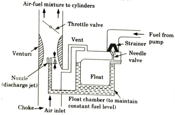
- 1. Air is sucked via the venturi during the suction stroke. A venturi is a tube with a decreasing cross section that has its smallest cross section near the throat.
- 2. As air passes through the venturi, its velocity rises and the throat’s pressure falls. Although this pressure is lower than atmospheric pressure, the pressure inside the float chamber caused by the fuel is atmospheric.
- 3. As a result, fuel is injected into the venturi’s discharge jet, through which air is forced during the suction stroke. Consequently, the carburetor prepares a mixture of fuel and air. The cylinder receives this mixture.
- 4. The jet is used to discharge fuel in the venturi. The jet’s size is decided upon empirically in order to provide the necessary engine performance.
Q3. Describe MPFI system with the help of neat sketch.
Ans.
- 1. An MPFI system is as shown in Fig.
- 2. The primary function of the MPFI system is to deliver the right proportion of fuel and air to the cylinders.
- 3. It consists of following three components:
A. Air Intake System:
- 1. With this system, the intake manifold distributes the air, which is then finally brought into each combustion chamber after being filtered by the air cleaner and passing through the throttle body.
- 2. The ECU regulates the throttle valve’s opening and shutting in accordance with demand and necessity using accurate calculations from the input system.
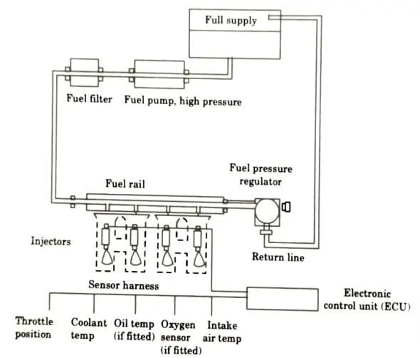
B. Fuel Delivery System:
- 1. Via the delivery pipe, each injector receives fuel under pressure that has been pushed up by the fuel pump, filtered by the fuel filter, and delivered into the fuel tank.
- 2. As the injector opens in response to the injection signal from the ECM, fuel is injected into the cylinder head’s intake port.
C. Electronic Control System:
- 1. The electronic control system is composed of a number of sensors that identify the condition of the engine and the driving environment.
- 2. It controls various devices according to the signals from the sensors and various controlled devices such as:
- i. Fuel Injection Control System,
- ii. Idle Speed Control System,
- iii. Fuel Pump Control System,
- iv Ignition Control System,
- v. Radiator Fan Control System.
Q4. How are the injection system classified ? Describe them briefly.
Ans. A. Classification of Injection System: There are two type of injection system:
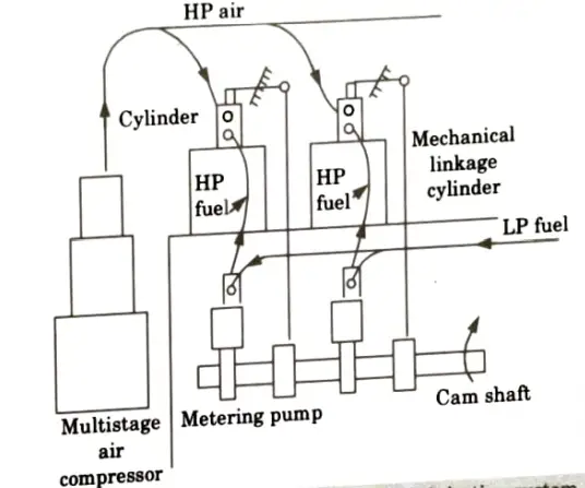
i Air Injection System:
- 1. With an air injection system, compressed air is used to force fuel into the cylinder.
- 2. A fuel pump that is operated by a camshaft measures and pumps fuel to the fuel valve.
- 3. The timing of injection is controlled by a linkage that is mechanically actuated by the camshaft, which opens the fuel valve.
- 4. A high pressure air line supplied by a multistage compressor is also attached to the fuel valve.
- 5. When the fuel valve is opened, the fuel is carried by high pressure into the combustion chamber and sprayed there as a droplet.
ii. Solid Injection System:
- 1. This technology does not first atomize the liquid fuel before injecting it into the combustion chamber.
- 2. This is also called air less mechanical injection.
- 3. Solid injection system can be classified into four types:
- i. Individual pump and nozzle system,
- ii. Unit injector system,
- iii. Common rail system, and
- iv. Distributor system.
B. Reason for not using the Air Injection System: A multistage compressor is employed in air injection systems, which reduces braking power output and increases engine size and weight. As a result, air injection systems are no longer used nowadays.
Q5. Draw a schematic diagram of fuel injection pump and explain its working principle.
Ans. A. Construction:
- 1. A fuel injection pump is shown in Fig.
- 2. It is made out of a barrel in which a plunger rotates when a camshaft is applied. The plunger only has one action.
- 3. The barrel and plunger have a very narrow clearance allowing the plungers to travel smoothly, and it also offers the Even at high pressure, the pump barrel’s input and control ports have flawless sealing.
- 4. A spring-loaded delivery valve is supplied at the top of the barrel.
- 5. To rotate the plunger and control the amount of fuel delivered every stroke, a rack and pinion arrangement is offered.
B. Working:
- 1. When the plunger is at its bottom stroke, the spill port and are uncovered supply port (as shown in Fig.) oil from pressure pump after being filtered is forced into the barrel.
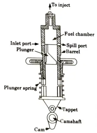
- 2. The cam and tappet mechanism causes the plunger to rise to a point where the supply and spill ports are both closed. As the plunger continues to rise, the fuel is compressed.
- 3. The delivery valve is lifted off its seats by the tremendous pressure that has been created, and fuel pours through the tube to the atomizer.
- 4. When the plunger continues to rise, the supply port eventually connects to the fuel in the top section of the plunger through the rectangular vertical groove by the helical groove, causing a dramatic reduction in pressure that causes the delivery valve to recoil and close against the pull of the spring.
Q6. Explain effect of turbocharger on power and emission.
Ans.
- 1. Turbochargers are utilised widely in the automotive industry because they may boost an internal combustion (IC) engine’s output without requiring it to have more cylinders.
- 2. The use of such a mechanical mechanism enables automakers to downsize their engines, often known as engine downsizing, to smaller displacements.
- 3. Turbochargers were frequently employed to boost the capabilities of an IC engine that was already very powerful.
- 4. Now, the focus is on offering a workable engineering solution for manufacturing economics and more environmentally friendly road vehicles. These factors have led to an increase in the use of turbochargers in car applications.
- 5. The purpose of turbocharging techniques is to boost engine production while lowering exhaust pollution levels.
- 6. A turbocharger enhances the amount of energy diesel produces by improving the combustion efficiency with which an engine burns diesel, and it decreases emissions by turning a greater proportion of diesel fuel into carbon dioxide or water instead of a hazardous exhaust.
- 7. Recycling waste energy from exhaust gas is the fundamental idea of a turbocharger, which increases the amount of fuel energy converted into power. Hence, a turbocharged engine outperforms a non-turbocharged engine in terms of performance, fuel efficiency, and CO2 emissions.
- 8. By maintaining the power and performance customers expect, turbocharging enables automakers to reduce engine sizes and, consequently, emissions.
- 9. Turbochargers offer the fastest response to global warming at a lower cost per vehicle than any other technology.

IC Engine, Fuel and Lubrication Btech Quantum PDF, Syllabus, Important Questions
| Label | Link |
|---|---|
| Subject Syllabus | Syllabus |
| Short Questions | Short-question |
| Question paper – 2021-22 | 2021-22 |
IC Engine, Fuel and Lubrication Quantum PDF | AKTU Quantum PDF:
| Quantum Series | Links |
| Quantum -2022-23 | 2022-23 |
AKTU Important Links | Btech Syllabus
| Link Name | Links |
|---|---|
| Btech AKTU Circulars | Links |
| Btech AKTU Syllabus | Links |
| Btech AKTU Student Dashboard | Student Dashboard |
| AKTU RESULT (One View) | Student Result |