With this AKTU question paper and solution, you can bring out the power of IC Engine, Fuel and Lubrication. Get thorough notes in PDF for an engaging tour through automotive engineering.
Dudes 🤔.. You want more useful details regarding this subject. Please keep in mind this as well.

Important Questions For IC Engine, Fuel and Lubrication:
*Quantum          *B.tech-Syllabus
*Circulars           *B.tech AKTU RESULT
* Btech 3rd Year
Section A: IC Engine, Fuel and Lubrication Short Notes
a. Define the term heat engine.
Ans. An apparatus that transforms heat energy into mechanical energy is a heat engine. It is accomplished by lowering the temperature of a working substance from one that is higher.
b. Discuss the term relative efficiency.
Ans. The proportion of the indicated thermal efficiency to the air standard efficiency is the relative efficiency of an IC engine.
c. Discuss the term ignition delay in CI engine.
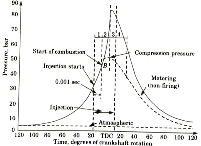
Ans. It is also referred to as the preliminary phase because some fuel has already been added during this time but has not yet started to burn. This time span is measured from the beginning of the injection process until the pressure time curve separates from the motoring curve, which is the beginning of combustion.
d. Explain the term ‘flame speed’ in SI engines.
Ans. 1. The lame front’s observed rate of expansion during a combustion event is known as the flame speed.
2. In an internal combustion engine, a fuel’s capacity to undergo controlled combustion without detonation depends on several factors, including the flame speed of the fuel.
e. Discuss the injection timings.
Ans. The timing at which fuel is injected into the inlet manifold is known as the “injection timing,” according to definition.
f. Explain the terms ‘lean and rich mixture’.
Ans. Lean Mixture: This particular sort of air-fuel mixture has more air than is necessary for the full combustion of the fuel.
Rich Mixture:This particular sort of air-fuel mixture contains less air than what is necessary for the full combustion of the fuel.
g. Discuss NOx emission.
Ans. 1. Nitric oxide (NO) and nitrogen dioxide make up the only other sources of nitrogen oxides, which are found only in engine exhaust (NO2).
2. At relatively high temperatures, nitrogen and oxygen react. Hence, the two primary causes of NOx generation are high temperatures and an abundance of oxygen.
h. Explain cetane number and diesel index for fuel.
Ans. Cetane Number: When combustion is carried out in a typical engine under predetermined operating circumstances, it is defined as the volume percentage of normal cetane in a combination of normal cetane and a-methyl naphthalene that has the same igniting properties as the test fuel.
Diesel Index: A low-cost approach of determining ignition quality is the diesel index. The diesel index, as opposed to a true determination in a test engine, provides an indication of the ignition quality gained from specific physical features of the fuel.
i. Explain working of radiator.
Ans. The radiator functions by forcing coolant through flimsy metal fins, which facilitate the heat’s easier transfer to the outside air. In order to move the hot air out of the engine, a fan blows air across the radiator.
j. Define stratified charge engine
Ans. It is an engine that falls somewhere in the middle of a heterogeneous charge compression ignition engine and a homogeneous charge spark ignition engine.
Section B: IC Engine, Fuel and Lubrication Important Notes
a. Discuss the classification of IC engines in detail.
Ans. Internal combustion engine can be classified as follows:
- i. According to Basic Engine Design:
- 1. Reciprocating engine, and
- 2. Rotary engine.
- ii. According to Working Cycle:
- 1. Otto cycle engine, and
- 2. Diesel cycle engine.
- iii. According to Number of Stroke:
- 1. Four stroke engine, and
- 2. Two stroke engine.
- iv. According to Fuel Employed:
- 1. Gasoline or petrol engine,
- 2. Diesel engine,
- 3. LPG engine, and
- 4. CNG engine.
- v. According to Fuel Supply and Mixture Preparation:
- 1. Carbureted type: Fuel is supplied through carburetor.
- 2. Injection type: Fuel injected into inlet port or inlet manifold.
- vi. According to Method of Ignition:
- 1. Battery ignition, and
- 2. Magneto ignition.
- vii. According to Method of Cooling:
- 1. Water cooled engine, and
- 2. Air cooled engine.
- viii. According to Cylinder Arrangement:
- 1. Inline engine,
- 2. V engine, and
- 3. Radial engine.
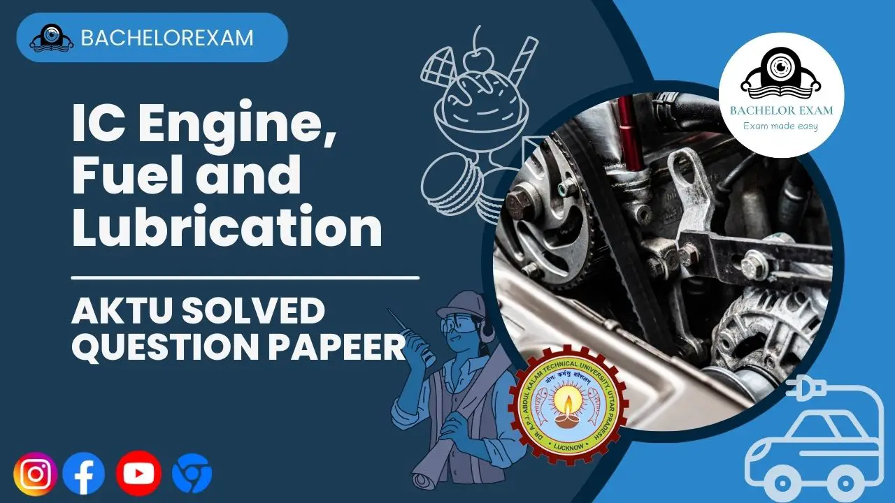
b. Explain with diagram the stages of combustion for SI engine.
Ans. Combustion phenomenon in SI engine can be described in following three stages:
Stage I: Ignition Lag or Preparation Phase:
- 1. The interval between the first igniting of fuel and the start of the primary phase of combustion is known as the ignition lag.
- 2. Stage I is thought to be starting right now because A is the point of spark.
- 3. Stage I is sort of a preliminary phase in which heat transfer from the flame and a few chemical reactions raise the temperature of the surrounding mix.
- 4. Point B designates the conclusion of phase I.
- 5. Point B is obtained as the point where p-𝜃 curve for combustion process depart from the normal motoring curve.
- 6. In motoring test, the spark plug is deactivated and engine is driven by a motor. So, the pressure variation is the same as it there was no combustion process.
Stage II: Flame Propagation:
- 1. After stage I, the mixture is better prepared to ignite since it has absorbed heat from the flame and its temperature has grown due to chemical reactions.
- 2. In this instance, the flame spreads quickly, consuming the mixture and releasing energy that is reflected in the elevated temperature and pressure.
- 3. End of stage II is the point C where the peak of pressure-angle (p-𝜃) curve reached.
Stage III: After Burning:
- 1. Following the flame propagation stage, energy is released as a result of numerous reassociation reactions.
- 2. Some energy is released as a result of the reassociation process, and some charge that could not burn in the second stage can now burn in this stage.
- 3 10% of the energy generated by fuel comes from the stage following combustion.
c. Evaluate the working of MPFI and its different types with the help of neat and clean diagrams.
Ans. A. Working of MPFI: The primary function of the MPFI system is to deliver the right proportion of fuel and air to the cylinders.
B. Types of MPFI: Various types of MPFI for SI engines are as follows:
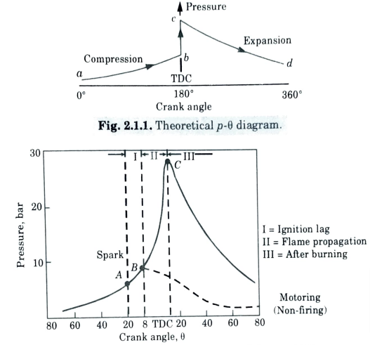
i. Port Injection:
- 1. In this sort of system, the injector is positioned close to the intake manifold of the intake port; as a result, petrol flows out of the injector and correctly mixes with air.
- 2. After that, the petrol and air combination enters the cylinder through the intake valve.
- 3. With this method, the number of injectors and cylinders are the same.
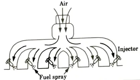
ii. Throttle Body Injection System:
- 1. As shown in Fig. an injector is placed near the throat of the throttle body.
- 2. On the intake manifold, where petrol and air mingle, the injector sprays fuel into the air.
- 3. The mixture then reaches the intake manifold through the throttle valve.
d. Illustrate particulate emissions and also give methods of controlling emissions.
Ans. A. Particulate Emissions: Particulate matter can be either dust (particles smaller than 1 micron in diameter) that does not settle to the ground or particles larger than 10 microns in diameter that do.
B. Methods of Controlling Emissions: Various methods of controlling of particulate emissions are as follows:
i. Cinder Catchers: The cinder catchers are shown in Fig. given below:
- 1. Fig.(a) shows sudden decrease in gas velocity makes the particulate separate and fall.
- 2. Fig.(b) shows a sudden change in the direction of flow of flue gas throws the particulates away and can be collected.
- 3. Flue gas impingement on a succession of baffle stops is depicted in Fig. (c), together with the particulate matter from the previous picture. They are frequently utilised in small cyclone and stoker furnaces, which burn crushed coal as opposed to very finely ground coal. Cinder catchers have collection efficiency ranging from 50 to 75%.
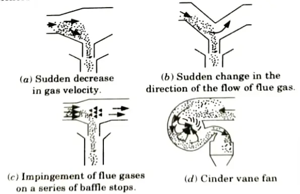
- 4. Fig.(d) shows a cinder vane fan. The cinder vane fan uses the fan which imparts centrifugal force to the particulates and they are collected as shown in figure. The efficiency is from 50 to 75%.
ii. Electrostatic Precipitator:
- 1. Fig. depicts an electrostatic precipitator. In this apparatus, wires hung in a gas-flow tube between two grounded plates are subjected to an extremely high voltage of 30 kV to 60 kV.
- 2. The negatively charged wires give the gas stream particles a charge, which attracts them to the ground plates. An electromagnet raises and lowers a steel plug, which periodically taps the grounded plates, collecting dust in the hoppers below.

- 3. Care must be taken to prevent a significant amount of unburned gases from entering the precipitator in this sort of collector. If such a mixture enters, electricity should be cut off because otherwise frequent sparking between wires and plates could create an explosion.
- 4. The collection efficiency is about 99 %.
- 5. Electrostatic precipitators are suitable for power plants where fly-ash content is high.
e. Summarize the requirements of a good cooling system and compare air and liquid cooling system in brief.
Ans. A. Requirement of Good Cooling System:
- 1. Just around 30% of the heat produced in the combustion chamber must be able to be removed by it. The thermal efficiency of the engine decreases with excessive heat removal.
- 2. When the engine is hot, it should dissipate heat quickly. The cooling process should be extremely gradual when the engine is started so that the various functioning components can quickly achieve their operational temperatures.
B. Comparison of Air and Liquid Cooling System:
| S. No. | Air Cooling | Liquid Cooling |
| 1. | There is no need for a radiator, water jacket, or pump. As a result, weight is decreased. | Pump and radiator requirements add to the vehicle’s weight. |
| 2. | The engine is smaller and has a much more straightforward design. | The dimensions and complexity of the engine are larger. |
| 3. | Warm-up performance of air cooled engine is better. | Warm-up performance of liquid cooled engine is poor. |
| 4. | Volumetric efficiency of air cooled engine is lower. | Volumetric efficiency of liquid cooled engines is higher. |
| 5. | Air cooled engine is less sensitive to climatic conditions. | Liquid cooled engine is more sensitive to climatic conditions. |
| 6. | Control of cooling system is much easier. | Control of cooling system is comparatively difficult. |
Section 3: Thermal Efficiency of Air Standard Otto Cycle
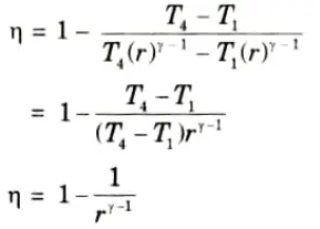
a. Discuss an expression for thermal efficiency of air standard Otto cycle.
Ans. 1. It is a constant volume cycle which is mainly used in petrol engine.
2. p-v and T-s diagrams are shown in Fig.(a) and (b) respectively.
3. This cycle consists of four processes:
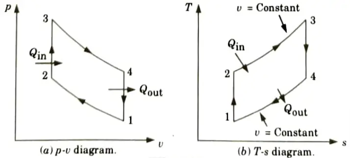
i. Process (1-2) :
1. It is isentropic compression.
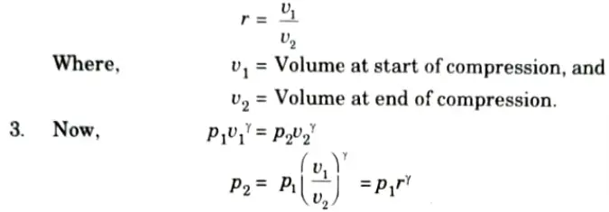
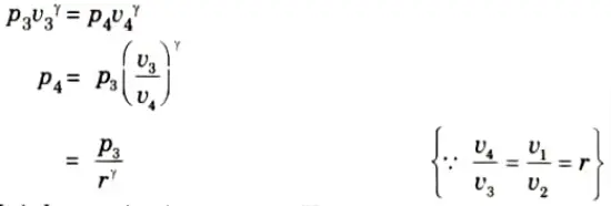
2. Ratio of v1 and v2 is known as compression ratio and it is denoted by r,
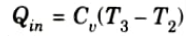
ii. Process (2-3): It is heat addition process. Heat is added during this process at constant volume.
iii. Process (3-4): It is isentropic expansion.
iv. Process (4-1): It is heat rejection process. Heat is rejected during this process at constant volume.
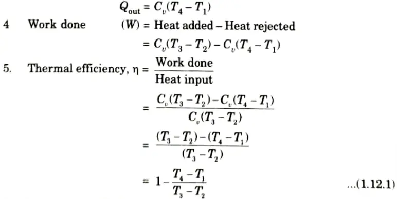
6. Since, process 1-2 and 3-4 are adiabatic, so
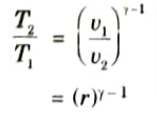
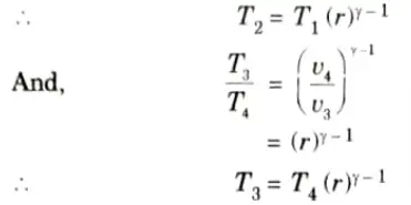
7. Putting these values in eq. (1.12.1), we have
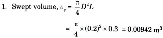
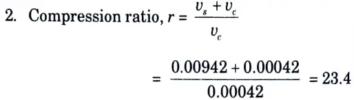
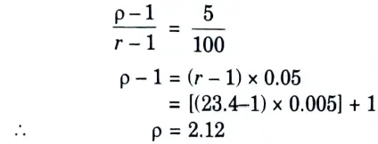
b. An IC engine working on Diesel cycle has bore 200 mm, stroke 300 mm. If the clearance volume is 4200 cc and fuel injection takes place at the constant pressure for 5 % of the stroke, determine the thermal efficiency of the engine. If the cut-off is delayed from 5 to 8 % what will be the percentage loss in efficiency in both cases? The compression ratio is the same.
Ans. Given: D = 200 mm = 0.2 m, L= 300 mm 0.3 m, vc = 420 cc = 0.00042 m3, 𝜌1 = 5 %, 𝜌2 = 8%
To Find: i. Thermal efficiency
ii. The percentage loss in efficiency
Data Assume: For air 𝛶 = 1.4
3. When the fuel is cut-off at 5 %, we have
4. Thermal efficiency,
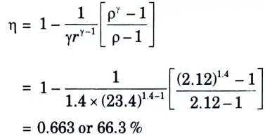
5. When the fuel is cut-off at 8 %, we have
6. Thermal efficiency,
7. Hence percentage loss in efficiency due to delay in fuel cut-off
= 66.3 – 63.7 = 2.6 %
Section 4: Knock in SI Engine
a. Demonstrate combustion process and its phases in CI engine with neat sketch.
Ans. Combustion phenomenon in CI engine can be explained in the following stages:
i. First Stage (Ignition Delay Period):
- 1. Although fuel is injected during this stage, it is not yet ignited. This is a stage of preparation.
- 2. Ignition delay is counted from the start of injection to the point where p-𝜃 curve separates from the pure air compression curve.
- 3. Ignition delay is composed of the two components:
a. Physical Delay:
- 1. The period of physical delay is the time between the beginning of injection and attainment of chemical reaction condition.
- 2. During this period fuel atomized, vaporized and mixed with air.
b. Chemical Delay:
- 1. In this phase, chemical reactions raise the mixture’s temperature until it reaches the self-ignition temperature, at which point ignition occurs.
- 2. Generally, chemical delay is longer than the physical delay.
ii. Second Stage (Rapid or Uncontrolled Combustion):
- 1. During the delay time, the rate of combustion is extremely high, and the fuel droplets in the fuel cylinder have gathered to the proper amount and are prepared to ignite.
- 2. Stage II starts from point B, and ends at the maximum pressure point of p-𝜃 curve.
iii. Third Stage (Controlled Combustion):
- 1. The temperature and pressure at the conclusion of the second stage of combustion are so high that the fuel droplets injected in the third stage of combustion burn nearly as soon as they enter. Any further pressure rise can be controlled by solely mechanical methods, i.e., by the injection rate.
- 2. It is expected that the regulated combustion period will conclude at the highest cycle temperature.
- 3. Between 70 and 80 percent of the heat released at the conclusion of controlled combustion.
iv. Fourth Stage (After Burning):
- 1. The inadequate distribution of fuel particles causes the burning to continue even after the fuel injection has stopped. As far as 70 to 80 degrees of the crank’s travel from TDC, this burning may continue during the expansion stroke. The after burning is the name given to this ongoing fire.
- 2. The reassociation reaction that occurs after fuel combustion here causes some energy to be released.
b. Demonstrate phenomenon of knock in SI Engine. Discuss the effects of knock in SI engines and methods to reduce the detonation.
Ans. A. Phenomenon of Knock in SI Engine:
- 1. Detonation is the term for a very rapid increase in pressure during combustion that is accompanied by a metallic hammer-like sound.
- 2. The detonation zone is the area that is farthest from the spark plug where detonation takes place.
- 3. Referring to Fig., which depicts a cross-section of the combustion chamber with flame emerging from spark plug site A, can help illustrate the detonation or knocking process.
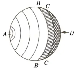
- 4. The end charge BB’D farthest from the spark plug is compressed by the moving flame front, increasing its temperature.
- 5. Heat transfer from the hot advancing flame front causes the temperature of the end charge to also rise. Moreover, end charge may experience some preflame oxidation, which will raise its temperature even more.
- 6. The end charge BB’D will auto-ignite and cause knocking combustion if it reaches its auto-ignition temperature and stays there for a while to finish the preflame reactions.
- 7. The flame front may travel from BB’ to CC’ during the pre-flame reaction time, and the knock is caused by the charge’s automatic ignition in front of CC’.
B. Effects of Knock:
- 1. Noise and roughness,
- 2. Mechanical damage,
- 3. Carbon deposits,
- 4. Increase in heat transfer,
- 5. Decrease in power output and efficiency, and
- 6. Pre-ignition.
C. Methods to Reduce the Detonation: The detonation can be controlled or even stopped by the following ways:
- 1. Increasing engine rpm.
- 2. Retarding spark.
- 3. Reducing pressure in the inlet manifold by throttling.
- 4. Making the ratio too lean or too rich, preferably latter
- 5. Water injection increases the delay period as well as reduces the flame temperature.
- 6. Use of high octane fuel can eliminate detonation.
Section 5: IC Engine, Fuel and Lubrication Important Numerical
a. Derive an expression for the calculation of exact A-F ratio when air is considered as incompressible.
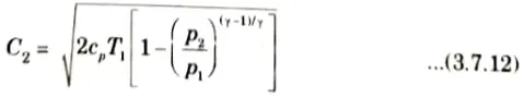
Ans. 1. When the compressibility of air is taken into account, the air flow will change but the fuel flow will remain unchanged. Applying steady flow energy equation (SHFEE) at section 1-1 and 2-2, we get,
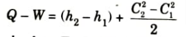
Where, h1, h2 = Enthalpies at section 1-1 and 2-2 respectively.
2. Since Q = 0, W = 0 and C1 = 0
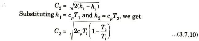
3. Since the flow process between the atmosphere and the venturi throat is isentropic,
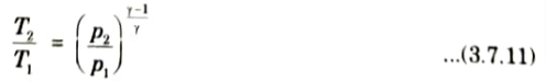
4. Substituting eq. (3.7.11) in eq. (3.7.10), we get
5. Now, the mass of flow of air is constant from inlet to venturi throat, and is given by,
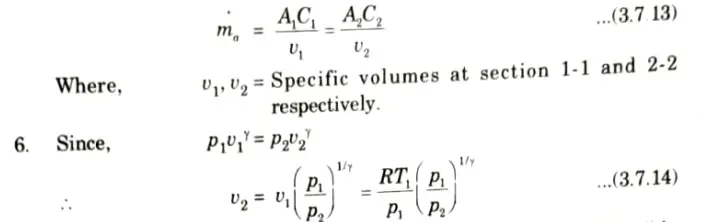
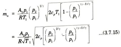
7. Substituting the values of C2 from eq. (3.7.12) and v2 from eq. (3.7.14) in eq. (3.7.13), we get theoretical mass flow of air,
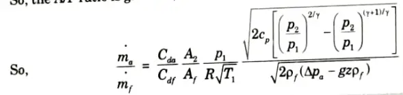
8. So, the A/F ratio is given as,
b. Derive an expression for the quantity of fuel to be injected per cylinder per cycle for a four-stroke engine in terms of brake specific fuel consumption, BP and rpm. Determine the velocity of injection of fuel in solid injection system when the difference in oil pressure and cylinder pressure is 75 bar. Assume the specific gravity of fuel as 0.905 and coefficient of discharge for orifice is 0.86.
Ans. A. Expression for the Quantity of Fuel:
1. Let, p1 = Injection pressure,
v1 = Velocity at section 1,
p2 = Pressure in the cylinder when injection of fuel takes place,
v2 = Velocity at section 2,
𝜌f = Density of fuel, and
vf = Specific volume of fuel,
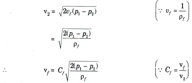
Cf = Flow coefficient of orifice, and
vf = Actual fuel velocity.
2. We know that,
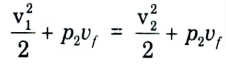
Neglecting v1 being very small compared to v2 we have
3. The volume of the fuel injected per second Qf is given by,
Qf = Area of all orifices x Fuel jet velocity x Time of injection x Number of injections per second for one orifice
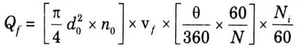
4. The above formula can be written as,
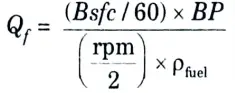
B. Numerical:
Given: Poil – Pcyl = 75 bar = 75 x 105 N/m2, specific gravity = 0.905, Cd = 0.86
To Find: Velocity of injection of fuel.
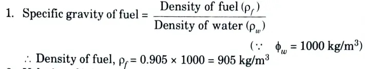
2. Velocity of injection of fuel,
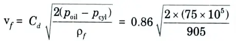
= 110.7 m/s
Section 6: Working of Catalytic Converter
a. Discuss EGR system. Also demonstrate the working of catalytic converter with neat sketch.
Ans. A. EGR:
- 1. Exhaust gas recirculation (EGR) is commonly used to reduce NOx in petrol as well as diesel engines.
- 2. In SIengines, about 10 percent recirculation reduces NOx emission by 50 percent.
- 3. Unfortunately, the consequently poorer combustion directly increases HC emission and calls for mixture enrichment to restore combustion regularity which gives a further indirect increase of both HC and CO.
- 4. A portion (about 10 % to 15 %) of the exhaust gases is recirculated to cylinder intake charge, and this reduces the quantity of O2 available for combustion.
- 5. The exhaust gas for recirculation is taken through an orifice and passed through control valve for regulation of the quantity of recirculation.
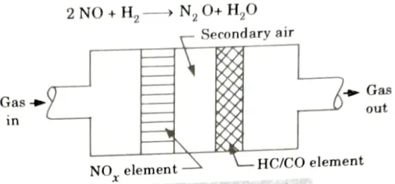
B. Catalytic Converter:
- 1. Little embedded pieces of catalytic material on the ceramic passageways’ surface support oxidation reactions in the exhaust gas as it flows through.
- 2. The most common type of ceramic material used in catalytic converters is aluminium oxide (alumina).
- 3. High temperatures can be withstood by alumina, which also maintains its chemical neutrality, has a very low thermal expansion, and does not undergo thermal degradation with time.
- 4. The catalyst materials most commonly used are platinum, palladium, and rhodium.
- 5. Palladium and platinum promote the oxidation of CO and HC.
- 6. Rhodium promotes the reaction of NOx in one or more of the following reactions:
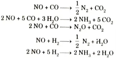
b. Discuss the alternative fuels for IC engines also discuss the rating for SI engine fuel.
Ans. A. Alternative Fuels:
- i. Biodiesel:
- 1. Biodiesel is regular diesel made from petroleum.
- 2. It is a result of non-toxic, biodegradable materials like animal and vegetable fats.
- ii. Bioethanol:
- 1. A renewable energy source that can be created from agricultural feedstocks is bioethanol.
- 2. It can be produced from widely grown plants like hemp, sugarcane, potatoes, cassava, and maize, among others.
- 3. Bioethanol has a high octane number.
- iii. Gasohol:
- 1. Gasohol is a mixture of petrol (gasoline) and alcohol (i.e. typically ethanol at 10 %, or methanol at 3 %).
- 2. It is obtained by fermenting agricultural crops or crop wastes.
- 3. Gasohol is more toxic and corrosive.
- iv. Hydrogen:
- 1. When burned with oxygen, hydrogen fuel produces no emissions.
- 2. A variety of domestic energy sources, including nuclear power and renewable energy, can be used to manufacture hydrogen.
- 3. Fuel with a high efficiency and little environmental impact is hydrogen.
B. Rating for SI Engine Fuel :
- i. HUCR:
- 1. The maximum compression ratio (HUCR) at which a fuel may be utilised in a specific test engine without causing a detonation depends on a number of factors, and best efficiency is achieved by adjusting the ignition and mixture strength.
- 2. This method of fuel rating is no more popular.
- ii. Octane Number:
- 1. Octane number is used to give the knock rating.
- 2. As the octane number is raised, the compression ratio rises. This suggests that the engine’s thermal efficiency and power output need to be improved.
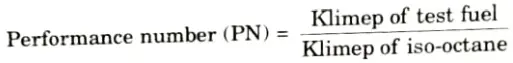
- iii. Performance Number:
- 1. Performance numbers are used to express the rating of fuels with octane numbers greater than 100.
- 2. It is the difference between the test fuel’s klimep—knock limited indicated mean effective pressure—and the isooctane klimep.
- iv. Cetane Number:
- 1. It is also known as cetane rating.
- 2. It is a measurement of the quality or performance of diesel fuel.
- 3. The higher the number, the better the fuel burns within the engine.
Section 7: Working of Battery Ignition System
a. Explain the function of lubricant in IC engines. Explain different wet lubricating system with neat sketch.
Ans. A. Function of Lubricants in IC Engines:
- 1. To lessen friction between components that are moving relative to one another.
- 2. To reduce surface temperatures by removing the heat produced by friction.
- 3. To wipe the carbon and metal debris from the engine component.
- 4. Ensure that the piston rings and cylinder walls are properly sealed.
- 5 to lessen moving engine component wear.
B. Wet Lubricating System:
- 1. The lubricating oil is located in the sump, which is the bottom portion of the crankcase in a wet sump lubrication system.
- 2. From the sump lubricating oil is supplied to various part of the engine.
- 3. Following are the three types of wet sump lubricating system:
a. Splash System:
- 1. In Fig. a splash system is shown. This type of system is used in light duty engines.
- 2. The lubricating oil is pumped into the engine crankcase’s bottom and charged there, where it is maintained at a predetermined level.
- 3. The oil is kept in the oil troughs under the connecting rod’s big end.
- 4. The huge end of the connecting rod dips into the oil trough when it is at its lowest position, splashing oil all over the crankcase’s interior, the piston and its rings, and the exposed position of the cylinder.
- 5. Next, extra oil is redirected to the sump.
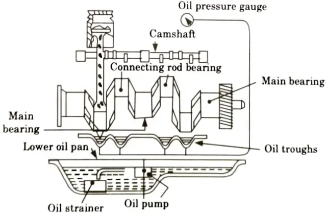
b. Splash and Pressure System:
- 1. This system is the combination of splash and pressure system.
- 2. The main camshaft bearings are lubricated by oil under pressure, pumped by an oil pump.
- 3. The other parts are lubricated by splash.
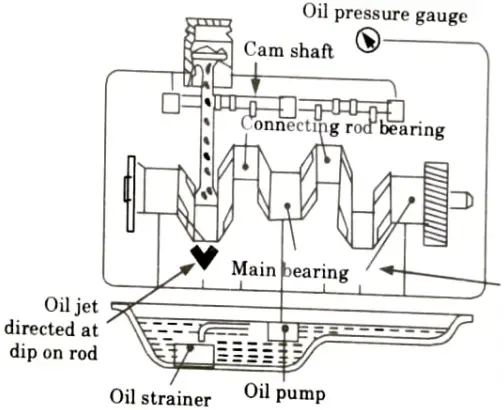
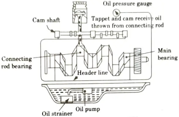
c. Pressure Feed System:
- 1. Engines subjected to heavy loads are employed with this technology.
- 2. An oil pump is employed in this arrangement to lubricate every component of the cylinder.
- 3. Oil is delivered by a pressure pump at 1.5 to 4 bar of pressure. The crankshaft and camshaft’s main bearings are supplied with oil that is under pressure.
- 4. To provide oil to the big end and small end bearings of the connecting rod, an oil hole is made in the crankshaft bearing.
- 5. The oil spray lubricates the cylinder wall, piston, and piston ring.
b. Explain the working of battery ignition system with neat sketch. Also discuss the types of electronic ignition system.
Ans. A. Working of Battery Ignition System:
- 1. A primary current from the battery will flow through the primary winding of the coil when the ignition switch is depressed.
- 2. The soft iron core contained within the secondary winding of the coil experiences a magnetic field as a result of this current.
- 3. The condenser is charged while the breaker point is open because current flows through it. The magnetic field collapses and primary current decreases as the condenser charges.
- 4. Field collapse creates a voltage in the primary winding that charges the condenser to a voltage that is significantly higher than the battery voltage.
- 5. The primary current and magnetic field are then reversed as the condenser discharges into the battery.
- 6. As a result, the secondary winding, which has a lot more turns than the main winding, experiences a very high voltage due to the rapid collapse and reversal of the magnetic field.
- 7. A spark arises between the spark plug electrodes as a result of the distributor directing the high secondary voltage to the right spark plug.
B. Types of Electronic Ignition System: There are two types of electronic ignition systems as follows:
i. Transistorised Coil Ignition System (TCI System):
- 1. Circuit diagram of TCI system is shown in Fig.
- 2. In this sort of system, a magnetic pulse generating system that monitors the position of the distributor shaft and sends an electrical pulse to an electronic control module replaces the contact breaker and cam assembly of conventional systems.
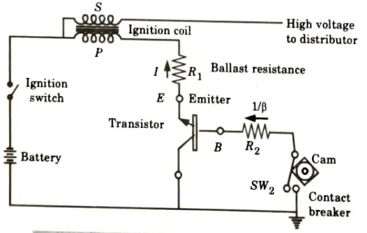
- 3. In this circuit, a transistor is utilised because it can regulate a significantly higher current in the collector circuit than in the base circuit, making it a suitable alternative for the breaker point and condenser.
ii. Capacitive Discharge Ignition System (CDI System):
- 1. A circuit diagram of CDI system is shown in Fig.
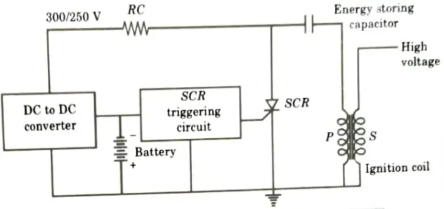
- 2. In this system a capacitor is used instead of ignition coil for storage of energy.
- 3. By using a transformer to charge it to a high voltage, it is then discharged at the point of ignition by a thyristor through the primary circuit, creating a high voltage pulse that fires the spark plug.
6 thoughts on “IC Engine, Fuel and Lubrication: Solved Previous Question Paper Aktu Notes”