
Aktu Btech Quantum Notes can help you learn more about IC engines, fuel, and lubrication. Prepare for your examinations by reviewing these frequently asked questions. Improve your performance right away! Unit-2 Combustion
Dudes 🤔.. You want more useful details regarding this subject. Please keep in mind this as well.

Important Questions For IC Engine, Fuel and Lubrication:
*Quantum                 *B.tech-Syllabus
*Circulars                  *B.tech AKTU RESULT
* Btech 3rd Year      * Aktu Solved Question Paper
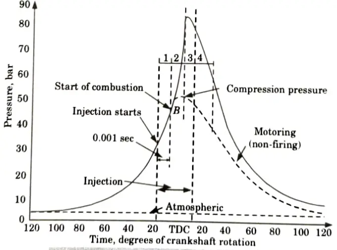
Q1. Explain the stages of combustion on p-𝜭 diagram in CI engine.
Ans. Combustion phenomenon in CI engine can be explained in the following stages:
i. First Stage (Ignition Delay Period):
- 1. Fuel is injected during this stage, but it is not yet ignited. This is a sort of preparation phase.
- 2. Ignition delay is counted from the start of injection to the point where p-𝜭 curve separates from the pure air compression curve.
- 3. Ignition delay is composed of the two components:
- a. Physical Delay:
- 1. The time between the start of the injection and the condition required for the chemical reaction is the period of physical delay.
- 2. During this period fuel atomized, vaporized and mixed with air.
- b. Chemical Delay:
- 1. In this phase, chemical reactions raise the mixture’s temperature until it reaches the self-ignition temperature, at which point ignition occurs.
- 2. Generally, chemical delay is longer than the physical delay.
ii. Second Stage (Rapid or Uncontrolled Combustion):
- 1. During the delay time, the rate of combustion is extremely high, and the fuel droplets in the fuel cylinder have gathered to the proper amount and are prepared to ignite.
- 2. Stage II starts from point B, and ends at the maximum pressure point of p-𝜭 curve.
iii. Third Stage (Controlled Combustion):
- 1. The temperature and pressure at the conclusion of the second stage of combustion are so high that the fuel droplets injected in the third stage of combustion burn nearly as soon as they enter. Any further pressure rise can be controlled by solely mechanical methods, i.e., by the injection rate.
- 2. It is expected that the regulated combustion period will conclude at the highest cycle temperature.
- 3. Between 70 and 80 percent of the heat released at the conclusion of controlled combustion.
iv. Fourth Stage (After Burning):
- 1. The inadequate distribution of fuel particles causes the burning to continue even after the fuel injection has stopped. This burning may continue in the expansion stroke upto 70 to 80 degree of crank travel from TDC. This prolonged burning called the after burning.
- 2. The reassociation reaction that occurs after fuel combustion here causes some energy to be released.
Q2. What are the factors which affecting combustion or flame propagation in IC engine.
Ans. Engine variables which affect the flame propagation are as follows:
- i. Compression Ratio: High compression ratio results in higher temperature and pressure, consequently increases the flame speed.
- ii. Ambient Pressure and Temperature: As inlet temperature and pressure rise, flame speed rises as well.
- iii. Air-fuel Ratio: When the mixture strength is 10% over the stoichiometric ratio, the maximum flame velocity occurs. The flame speed is slowed down as the mixture is made leaner.
- iv. Turbulence: The better the charge is mixed, the faster the flames burn, but too much turbulence is bad since it causes more heat to be lost to the environment, lowering the temperature of the mixture.
- v. Engine Load: As the load is raised, temperature and pressure inside the cylinder rise. As a result, flame speed increases with load.
- vi. Engine Speed: The mixture’s turbulence is reduced with a lower engine speed, which results in a slower flame speed.
Q3. Explain the different factors affecting detonation in SI engine.
Ans.
- i. Fuel Choice: Knock is encouraged by a low self-ignition temperature.
- ii. Induction Pressure: The temperature required for self-ignition and the induction time decrease as pressure rises. At full throttle, knock is more likely to happen.
- iii. Engine Speed: Low engine speeds will result in low turbulence, low flame velocities, and knock (combustion duration is constant in angle).
- iv. Ignition Timing: Advanced ignition timing increases peak pressure and promotes knock.
- v. Mixture Strength: Optimum mixture strength gives high pressures and promotes knock.
- vi. Compression Ratio: The cylinder pressures rise with a high compression ratio, which encourages knock.
- vii. Combustion Chamber Design: Long flame paths, weak turbulence, and insufficient cooling all result from bad design, all of which encourage knock.
- viii. Cylinder Cooling: Poor cooling raises the mixture temperature and promotes knock.
- ix. Engine Load: Fuel burning increases along with an increase in engine load. The temperature of the cylinder rises as a result of increased fuel combustion, which also enhances knocking in SI engines.
Q4. Discuss factors affecting combustion chamber design.
Ans. Following are the factors affecting combustion chamber design:
i. Swirl:
- 1. It is the charge moving in a circular motion around the cylinder’s axis. When the induction (also known as inlet) port passage is positioned so that the flow enters the cylinder tangentially, induction swirl is produced.
ii. Swirl Ratio:
- 1. Cylinder air swirl is the angular rotational speed of air about the cylinder axis. For convenience it can be related to the angular rotational speed of the crankshaft, the ratio of the two being called as swirl ratio i.e.,
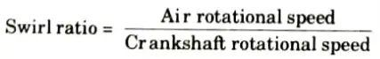
- 2. With helical ports, swirl ratio of 5 at TDC can be achieved with a flat piston crown, which can be increased to 15 in case of piston with bowl.
iii. Surface to Volume Ratio:
- 1. The larger this ratio, the higher the heat losses and cooler the combustion chamber walls will be, which will lead to a higher concentration of hydrocarbons in the exhaust stream.
- 2. As a result, the surface to volume ratio should be as low as possible to reduce the production of hydrocarbons.
- 3. The spherical kind of combustion chamber has the least surface area per unit volume. The chamber with the lowest surface to volume ratio is a double hemispherical one.
- 4. Surface to volume ratios in chambers with tiny quench areas are low.
- 5. The surface to volume ratio rises as compression ratio increases.
Q5. What are the types of combustion chamber used in SI engines ?
Ans. Various types of combustion chamber used in SI engines are as follow:
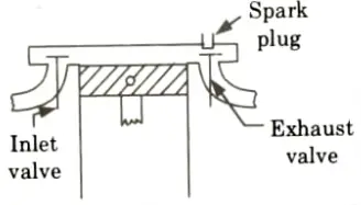
i. T-Head Combustion Chamber:
- 1. This type of combustion chamber has inlet and exhaust valves on opposite side of cylinder.
- 2. The spark plug is located near the exhaust.
- 3. It has the following characteristics:
- i. Good turbulence.
- ii. Short cylinder block.
- iii. Long flame travel and greater tendency to knock.
- iv. Unsatisfactory fuel and air utilization.
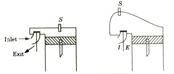
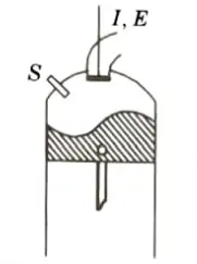
ii. L-Head Combustion Chamber:
- 1. This is a T-type combustion chamber modification.
- 2. The two valves in this combustion chamber are on the same side of the cylinder and are controlled by a single camshaft.
- 3. The main objectives of the Ricardo’s turbulent head design as shown in, Fig. is to obtain fast flame speed and reduced knock.
- 4. It has following characteristics:
- i. Provide high turbulence.
- ii. Short flame travel.
- iii. High power output.
- iv. Design is better than T and P type.
iii. I-Head Type or Overhead Valve:
- 1. In this type, both the valves are located on the cylinder head.
- 2. The overhead valve engine is superior to a side valve or an L-head engine at high compression ratio.
- 3. Some of the important characteristics of this type of valve arrangement are:
- i. Very high turbulence.
- ii. Smooth operation.
- iii. Higher volumetric efficiency.
- iv. High output.
iv. F-Head Combustion Chamber:
- 1. An F-head combustion chamber is one that has one valve in the head and the other in the block.
- 2. Although the performance of this design is superior to that of a T-head type combustion chamber, the valve operating mechanism is intricate and calls for two sets of cam shafts.
Q6. What do you understand by squish and tumble method of intensifying the rate of burning?
Ans. i. Squish:
- 1. The volume around the combustion chamber’s outlet margins is suddenly decreased to a very tiny value as the piston nears TDC at the end of the compression stroke.
- 2. The majority of clearance volume is frequently located close to the cylinder’s centerline in contemporary combustion chamber designs.
- 3. As the cylinder’s outside volume is decreased to almost nothing, the gas mixture that is occupying that space is driven radially inward. Squish is the name for this radial inward motion of the gas mixture.
- 4. It combines with other internal mass motions to quickly spread the flame front and mix the air and fuel.
ii. Tumble:
- 1. Squish motion causes a secondary rotating flow known as tumble when the piston approaches TDC. Its spin revolves around a circumferential axis close to the piston bowl’s outside edge.

IC Engine, Fuel and Lubrication Btech Quantum PDF, Syllabus, Important Questions
| Label | Link |
|---|---|
| Subject Syllabus | Syllabus |
| Short Questions | Short-question |
| Question paper – 2021-22 | 2021-22 |
IC Engine, Fuel and Lubrication Quantum PDF | AKTU Quantum PDF:
| Quantum Series | Links |
| Quantum -2022-23 | 2022-23 |
AKTU Important Links | Btech Syllabus
| Link Name | Links |
|---|---|
| Btech AKTU Circulars | Links |
| Btech AKTU Syllabus | Links |
| Btech AKTU Student Dashboard | Student Dashboard |
| AKTU RESULT (One View) | Student Result |