
Aktu Btech Quantum Notes can help you improve your understanding of IC Engines, Fuel, and Lubrication. Prepare for your examinations by answering these frequently asked questions. Improve your performance right now! Unit-1 Introduction to IC Engines
Dudes 🤔.. You want more useful details regarding this subject. Please keep in mind this as well.

Important Questions For IC Engine, Fuel and Lubrication:
*Quantum                 *B.tech-Syllabus
*Circulars                  *B.tech AKTU RESULT
* Btech 3rd Year      * Aktu Solved Question Paper
Q1. Classify the internal combustion engine.
Ans. Internal combustion engine can be classified as follows:
- i. According to Basic Engine Design:
- 1. Reciprocating engine, and
- 2. Rotary engine.
- ii. According to Working Cycle:
- 1. Otto cycle engine, and
- 2. Diesel cycle engine.
- iii. According to Number of Stroke:
- 1. Four stroke engine, and
- 2. Two stroke engine.
- iv. According to Fuel Employed:
- 1. Gasoline or petrol engine,
- 2. Diesel engine,
- 3. LPG engine, and
- 4. CNG engine.
- v. According to Fuel Supply and Mixture Preparation:
- 1. Carbureted type: Fuel is supplied through carburetor.
- 2. Injection type: Fuel injected into inlet port or inlet manifold.
- vi. According to Method of Ignition:
- 1. Battery ignition, and
- 2. Magneto ignition.
- vii. According to Method of Cooling:
- 1. Water cooled engine, and
- 2. Air cooled engine.
- viii. According to Cylinder Arrangement:
- 1. Inline engine,
- 2. V engine, and
- 3. Radial engine.
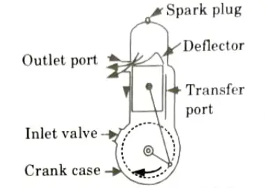
Q2. Explain the working of two stroke engine with a suitable sketch.
Ans.
- 1. With a two-stroke engine, the job is finished after two piston strokes or one crankshaft revolution.
- 2. Air compressed in the crankcase or the blower creates suction in a two-stroke engine. The combustion byproduct is eliminated by the introduction of compressed air into the cylinder. Hence, suction and exhaust do not require separate piston actions.
- 3. As the piston rises during the compression stroke, the air or charge is sucked through the spring-loaded inlet valve.
- 4. Ignition and expansion proceed as usual after compression. The air in the crankcase is compressed during the expansion stroke.
- 5. The piston uncovers the exhaust openings at the end of the expansion stroke. The cylinder pressure drop to ambient temperature as the combustion product leaves the cylinder.
- 6. As the piston continues to descend, the transfer apertures become visible, allowing the crankcase’s gently compressed air to enter the cylinder space.
Q3. Discuss the valve timing diagram for 4 stroke SI engine.
Ans.
- 1. Fig. shows the theoretical valve timing diagram for four stroke SI engine. In which energy stroke is shown by the angle of 180° of crankshaft rotation.
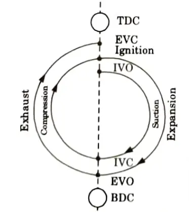
- 2. But it is difficult to open and close the valve so instantaneously.
- 3. Due to this reason actual valve timing diagram is different from the theoretical valve timing diagram. Actual valve timing diagram is shown in Fig.
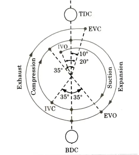
- 4. To allow the fresh charge to enter the cylinder and let the burned gases escape into the atmosphere, the inlet valve is opened 10° to 30° before the TDC position.
- 5. The charge’s suction continues up to 30 to 40 degrees beyond the BDC Inlet valve is now closed, and compression process begins.
- 6. The spark is generated by the spark plug 30 to 40 degrees before TDC, giving the fuel more time to burn. Around 10° past the TDC, the pressure reaches its peak.
- 7. The exhaust valve opens 30 to 60 degrees before BDC, allowing burned gases to exit the cylinder as the piston rises.
- 7. After that exhaust valve closes at 10° past the TDC.
Q4. Explain the significance of fuel-air cycle.
Ans.
- 1. The fuel-air cycle may be estimated for different fuel air ratios, inlet pressures, and temperatures in contrast to the air standard cycle, which only displays the overall influence of compression ratio on engine efficiency.
- 2. The fuel-air cycle analysis provides a good estimate of the power that can be anticipated from the real engine.
- 3. Peak pressures and exhaust temperatures, which have an impact on the engine’s construction and design, can be very carefully estimated with the use of fuel-air cycle analysis.
- 4. The effect of numerous engine variables can be understood better through fuel-air cycle analysis.
Q5. Explain the Willan’s line and Morse test in detail.
Ans. The friction power of an engine is determined by following method:
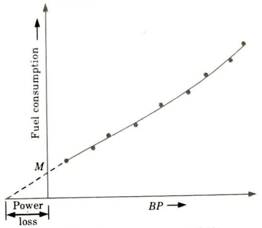
i. Willan’s Line Method:
- 1. This method involves plotting gross fuel usage versus brake power (BP) at a constant speed.
- 2. The load is decreased gradually while maintaining a steady speed, and the appropriate data for BP and gross fuel consumption are taken.
- 3. Next, a graph between fuel consumption and BP is created, with the BP axis extrapolated back to indicate the engine’s friction power at that speed.
ii. Morse Test:
- 1. Only multicylinder SI or CI engines are eligible for the Morse test.
- 2. After starting the engine, the required speed is reached, and the output is recorded. Then, one cylinder is shut off by either cutting the injector or shorting the spark plug.
- 3. In this scenario, this cylinder cuts out along with every other cylinder.
- 4. The output is calculated by maintaining the speed at its initial value.
- 5. The difference in the output is a measure of the suggested power of the cut off cylinder. In order to get the total IP of the cylinder, we can calculate the suggested power for each additional cylinder.
iii. Motoring Test:
- 1. The engine is initially accelerated to the required speed under its own power, then allowed to remain at that speed and load for a period of time so that the temperature of the oil, water, and engine components reaches a stable level.
- 2. During this time, a dynamometer absorbs the engine’s power.
- 3. After cutting off the fuel supply, the dynamometer is switched to operate as an electric motor to power the engine.
- 4. A measurement of the engine’s FP is made by measuring the power delivery to the motor.
Q6. A single cylinder and 4 stroke cycle IC engine when tested, the following observations available : Area of indicator diagram = 3 sq.cm, Length of indicator diagram = 4 cm, Spring constant= 10 bar/cm, Speed of engine = 400 rpm, Brake drum diameter = 120 cm, Dead weight on brake = 380 N, Spring balance reading 50 N, Fuel consumption = 2.8 kg/hr, CV = 42000 kJ/kg, Cylinder diameter = 16 cm, Piston stroke = 20 cm. Find:
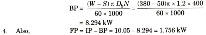
i. FP,
ii. Mechanical efficiency,
iii. bsfc, and
iv. Brake thermal efficiency.
Ans. Given: A = 3 cm2, Spring constant 10 bar/cm, Length of indicator
diagram = 4 cm, W = 400 rpm, W = 380 N, S = 50 N, Db = 120 cm
= 1.2 m, mf = 2.8 kg/h, CV = 42000 kJ/kg, D = 16 cm = 0.16 m,
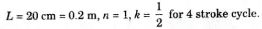
1. Indicated mean effective pressure,

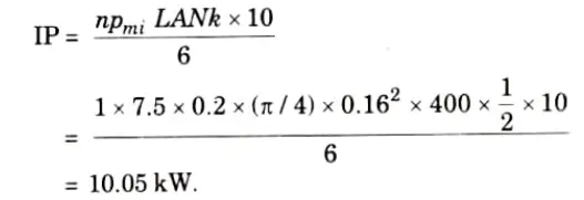
2. Indicated power,
3. Brake power,
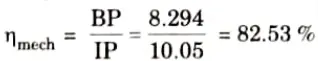
5. Mechanical efficiency,
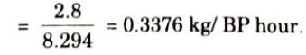
6. Brake specific fuel consumption,
bsfc = Fuel consumption per BP hour
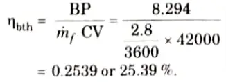
7. Brake thermal efficiency,

IC Engine, Fuel and Lubrication Btech Quantum PDF, Syllabus, Important Questions
| Label | Link |
|---|---|
| Subject Syllabus | Syllabus |
| Short Questions | Short-question |
| Question paper – 2021-22 | 2021-22 |
IC Engine, Fuel and Lubrication Quantum PDF | AKTU Quantum PDF:
| Quantum Series | Links |
| Quantum -2022-23 | 2022-23 |
AKTU Important Links | Btech Syllabus
| Link Name | Links |
|---|---|
| Btech AKTU Circulars | Links |
| Btech AKTU Syllabus | Links |
| Btech AKTU Student Dashboard | Student Dashboard |
| AKTU RESULT (One View) | Student Result |