There are many tools available to help you study for your exams, including Design of Steel Structures: AKTU Solved Question Paper. The answers to the questions have been carefully created in order to improve your comprehension of the concepts, involve you in problem-solving activities, and help you choose the topics that are most pertinent for successful exam preparation.
Dudes 🤔.. You want more useful details regarding this subject. Please keep in mind this as well.

Important Questions For Design of Steel Structures:
*Quantum          *B.tech-Syllabus
*Circulars           *B.tech AKTU RESULT
* Btech 4th Year
Section A: Short Question Design of Steel Structures
a. Write the advantages of steel structure.
Ans. Advantages of steel structure:
- i. It has assured quality and high durability.
- ii. Material is reusable.
- iii. It has high strength per unit area.
b. What are the seismic forces ?
Ans. Seismic forces are forces of inertia. When an object, like as a building, encounters acceleration, inertia force is produced when the mass resists the acceleration.
c. How you classified the connections provided in steel structures ?
Ans. The following three types of connections may be made in steel structure :
- i. Riveted.
- ii. Bolted.
- iii. Welded.
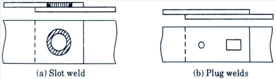
d. Draw the neat sketch of slot and plug welds.
Ans.
e. What do you understand by block shear failure ?
Ans. Block shear failure is defined as the tearing off of a segment or block of material at the end of a member in specific connection configurations and in coped beam.
f. Define shear leg.
Ans. The stress distribution over the flange as a result is non-uniform. Shear lag is the name given to this phenomena. It is determined by the width-to-span ratio, beam end constraints, and load categories.
g. What are the compression members ?
Ans. A compression member is a straight structural member that is subjected to two equal and opposing compressive forces at its ends.
h. Define squashing.
Ans. Squashing occurs in relatively small length columns. It occurs by yielding of a cross section of the column.
i. What are the spandrel beams ?
Ans. Spandrels are outside beams at the floor level of structures that carry a portion of the floor weight as well as the load of the outer wall.
j. What are the two important assumptions have to be made to achieve the ideal beam behavior?
Ans. Two important assumptions are made to achieve ideal beam behaviour :
i. Compression flange of beam is restrained from moving laterally.
ii. Any form of local buckling is prevented.
Section B: Question Answers of Design of Steel Structures
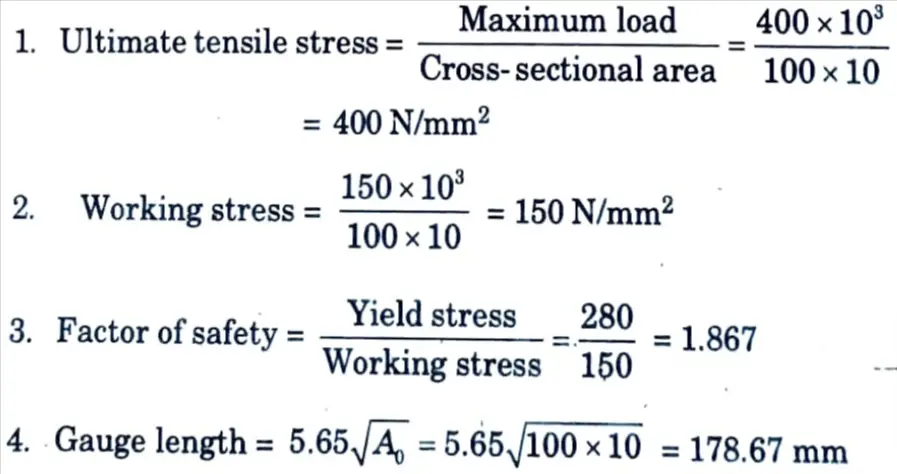
a. A tension bar 100 mm x 10 mm is to carry a load of 150 kN. A specimen of the same quality steel of cross section are 800 mm2, was tested in workshop. The maximum load carried by the specimen was 400 kN. Find the ultimate tensile strength, factor of safety in the design and gauge length.
Ans. Given: Load = 150kN, Cross-section of steel =800 mm2, Maximum load carried by specimen = 400 kN
To Find: Ultimate tensile strength, Factor of safety and Gauge length.
Assume yield stress = 280 N/mm2
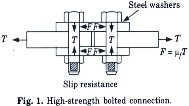
b. With neat sketch explain how force transfer of HSFG bolts.
Ans. High-Strength Bolts :
- 1. The high-strength bolts Fig. 1 are made from bars of medium carbon heat treated steel and from alloy steel.
- 2. They attain their high strength through quenching and tempering operations or by alloying steel.
- 3. These bolts can be tightened to very high tensile stresses, two or more times that of typical bolts, so that the connecting pieces are clamped securely together between the bolts and nut heads, allowing loads to be carried predominantly by friction rather than shear.
- 4. Thus, for high-strength bolted joints the transfer of forces is accomplished through the friction between the interfaces formed between load carrying elements jointed as shown in Fig. 1.
- 5. Due to this friction, the slip in the joint, which is there in joints with ordinary bolts, is eliminated.
- 6. Friction is created by putting a normal load to the joint and tightening these bolts to proof load.
- 7. This is why these bolts are often referred to as friction-type bolts. Non-slip connection, slip-critical connection, or friction-type connection refers to a joint made with a high-strength friction-grip bolt.
- 8. Hard steel or carburized steel washers are provided to equally distribute clamping pressure on the fastened member and prevent the threaded portion of the bolt from bearing on the connecting pieces.
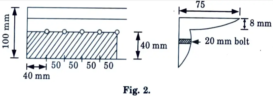
c. Design a suitable angle section to carry a factored tensile force of 210 kN assuming a single row of M20 bolts. The yield strength and ultimate strength of the material is 250 MPa and 410 MPa, respectively. The length of the member is 3 m.
Ans. Given : Factored tensile force, Pu = 210 kN, Bolt = M20, Yield strength 250 MPa, Ultimate strength = 410 MPa, Length of the member, L = 3 m.
To Find: Design angle section.
1. From the consideration of yield strength, grass area of the angle required = fy Ag/γm0
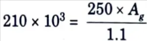
Ag = 924 mm2
2. Try ISA 100 x 75 x 8 mm which has grass area, Ag = 1336 mm2 Diameter of bolt hole = 20 + 2 = 22 mm
Assume thickness of gusset plate = 10 mm
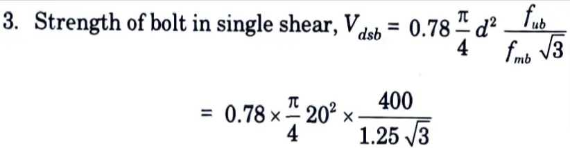
= 45272.43 N = 45.3 kN
4. The strength of bolt in bearing, Vdpb = 2.5kbdt fu/γmb
i. Edge distance, e = 1.7 x 22 = 37.4 mm
Assume edge distance is 40 mm
ii. Pitch of bolt, p = 2.5 d = 2.5 x 20 = 50 mm
iii. kb is smaller of e / 3dn, p / 3dn – 0.25, fub / fy and 1
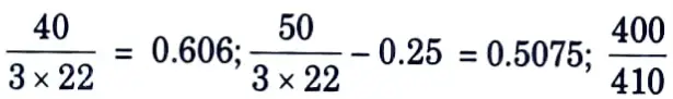
= 0.9756 and 1
Hence kb = 0.508
Vdpb = 2.5 x 0.508 x 20 x 8 x 410/ 1.25 = 66.65 kN
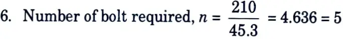
5. The strength of the bolt will be minimum of the strength in shear and bearing and is 45.3 kN
7. Checking for the Design :
i. Strength against gross section yielding,
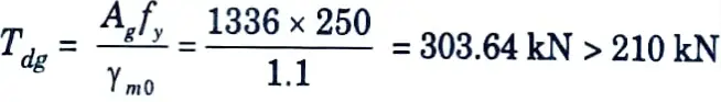
ii. Strength of Plate in Rupture :
a. Net area of the connected leg, Anc = (100 22 – 8/2) x 8 – 592 mm2
b. Gross area of outstanding leg, Ago = (75- 8/2) × 8 = 568 mm2
c. Design strength governed by tearing of net section is given by,
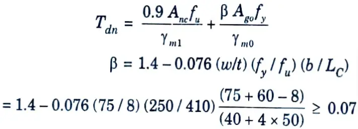
1.17 ≥ 0.07
= 325.794 kN > 210 kN
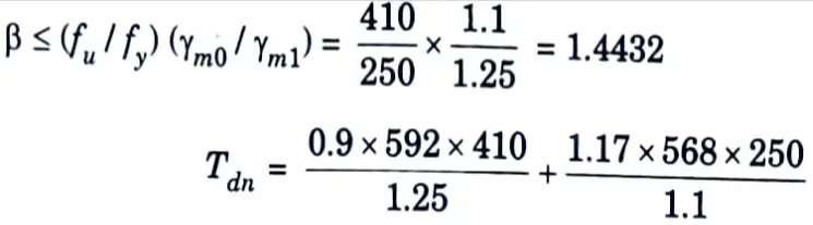
iii. Strength against block shear failure :
a. Avg = (40 + 4 x 50) x 8 = 1920 mm2
b. Avn = (40 + 4 x 50 4.5 x 22) x 8= 1128 mm²
c. Atg = 40 x 8 = 320 mm2
d. Atn = (40 22/2)8 = 232 mm2
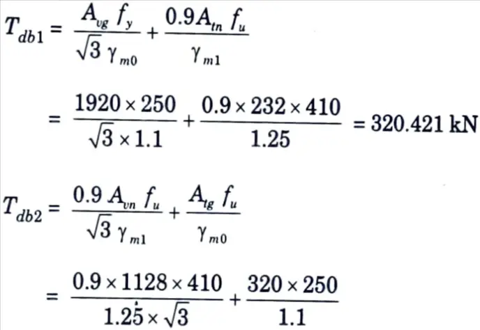
= 264976.6 N = 265 kN
The block shear strength is 265 kN > 210 kN
Hence design is safe.
d. Determine the design axial load on the column section ISMB @710.3 N/m, height of column is 4 m and is pin-ended. Assume that fy = 250 N/mm², E = 2 x 10⁵ N/mm².
Ans. Given: Column section = ISMB 450 @710.3 N/m, Length of column, L = 4m, E = 2 x 10⁵ N/mm2, fy = 250 N/mm2
To Find: Design axial load
Assume: Partial safety factor for material. γm0 = 1.1
1. The properties of ISMB 450 @ 710.3 N/m section are :
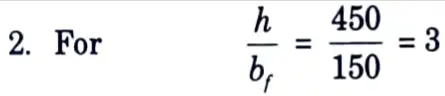
i. Height of section, h = 450 mm
ii. Width of flange, bf = 150 mm
iii. Thickness of flange, tf = 17.4 mm
iv. Thickness of web, tw = 9.4 mm
v. Effective area, Ae = 9227 mm2
vi. rz = 181.5 mm
vii. ry = 30.1 mm
and tf = 17.4 mm ≤ 40 mm
3. Design compressive stress about Y-Y axis :
i. Imperfection factor, α = 0.34 (for buckling curve b)
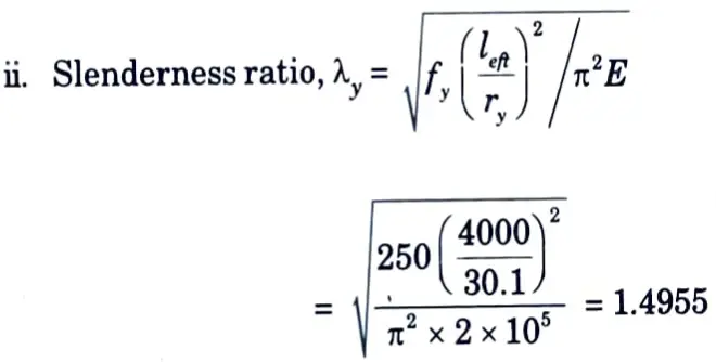
iii. ɸy = 0.5 x [1 + α(λy – 0.2) + λy2]
= 0.5[1 + 0.34 (1.4955 0.2) + 1.49552]= 1.8385
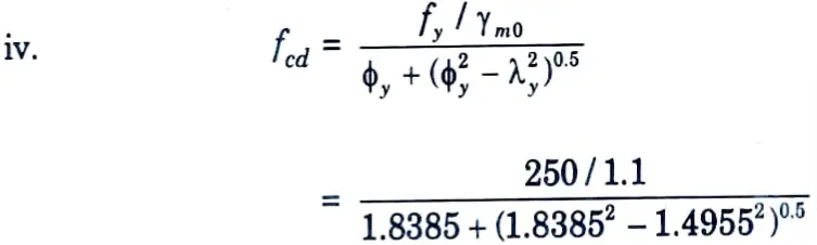
fcd = 78.158 Nmm²
v. Design compressive strength,
Pd = Acfcd = 9227 x 78.158 = 721163.866 N Pd = 721.164 kN
e. Write the design procedure of I-section purlins.
Ans. The design of a purlin is a trial and error procedure and is done as follows :
1. The gravity load P1 due to sheeting and live load, etc, and the load H1 due to wind are computed. These loads are multiplied with load factors γf to get the factored loads. Thus, P = γfP1,H = γfH1
2. The maximum bending moment Muu and Mvv are calculated as,
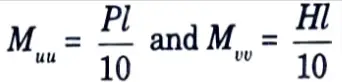
3. Purlins are subjected to biaxial bending, and require trial and error method for their design. A trial section is selected and the properties b and d are noted. The required value of section modulus may be determined from the following expression.
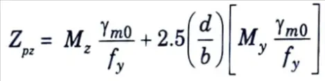
where, d = Depth of the trial section.
b = Width of trial section.
4. The design capacities of the section M, and M, are given by,
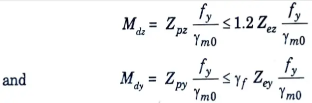
For safety, Mdz ≥ Mz and Mdy ≥ My
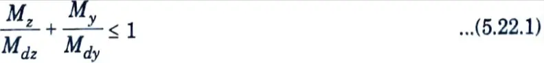
5. The local capacity of the section is checked using the following interaction equation.
6. The deflection of the purlin is calculated which should be less than l / 180.
7. Due to suction effect of wind, the design strength about ZZ-axis is calculated by,
Mdz = βb Zp fbd
8. The design capacity of the member is checked by Eg. (5.22.1), but with Mdz and Mdy as determined in steps 7 and 4, respectively.
Section 3: Btech Questions Design of Steel Structures
a. Explain cold formed light gauge sections and what are the problem associated with light gauge sections ?
Ans. A. Cold Formed Section :
- 1. The cold formed steel (CFS) segment refers to products created by rolling or pressing thin gauge steel sheets into articles.
- 2. CFS items are produced by manipulating thin steel sheets with stamping, rolling, or presses to deform the steel sheets into a useable product.
- 3. CFS products are manufactured at room temperature with the use of rolling/pressing. The buckling property is used to assess element strength. Construction procedures are similar to timber framing in that stud frames are assembled using screws.
- 4. CFS members’ applications include buildings, bridges, automobile bodies, storage tanks, highway items, railway coaches, gearbox towers, drainage facilities and so on.
- 5. The thicknesses of thin-walled steel members typically range from 0.4 mm to 7 mm. Steel plates and steel bars with a thickness of 25.4 mm can be cold moulded into structural shapes. Steel sheets used in the CFS construction process should have a yield strength of at least 280 MPa.
- 6. The mechanical properties of steel material change as it is manufactured via pressing due to the cold working material. The yield and ultimate strength of the steel section made from steel plates/sheets are increased.
- 7. The zinc or galvanising coating is applied to the cold-formed steel parts to protect them from corrosion in the environment. Coatings with a thickness of 0.04 mm are often used for internal environments. If moisture is present for an extended period of time, a thicker coat is applied for added protection.
- 8. In comparison to hot rolled sections, cold rolled sections have larger moment of inertia and section modulus in the x and y directions, resulting in greater load carrying ability and moment resisting capacity.
B. Problems Associated with Cold Formed Section :
- 1. One of the primary challenges with cold formed steel structures is cost. Cold rolled steel is twice as expensive as hot rolled steel.
- 2. Buckling is a major issue in cold formed steel elements. Cold-formed sections typically exhibit local buckling, global buckling, distortional buckling, and shear local buckling.
- 3. Web Crippling is a significant issue with cold formed steel sections. Web crippling can occur when there is a concentrated load in support. When stiffener cannot be provided in cold formed parts, this issue becomes apparent.
- 4. Cold formed steel sections have some ductility and plastic design limitations. Sectional buckling and the influence of cold forming by strain hardening degrade ductility and limit the plastic design options. Cold formed steel sections, as a result of their limited ductility, do not diffuse energy in seismic resistant constructions. Nonetheless, due to its high strength-to-weight ratio, it can be used in such structures, but only the elastic design is permitted.
- 5. Cold formed steel structures have issues with connection methods. Because of the extremely thin thickness, standard bolting and welding connection systems are not always appropriate. Cold-formed steel constructions are reinforced using blind rivets, self-drilling and tapping screws, fired pins, and cutting-edge technologies such as press joining, clinching, and rosette systems. As a result, the connection design is more complex and difficult for engineers.
- 6. Fire : Small section factor of cold formed steel sections makes it more fire susceptible.
- 7. Corrosion Protection : Corrosion resistance board, spray and other protection are applied to cold formed steel which can increase the cost and affect the architectural view.
b. A steel chimney 2.5 m diameter is situated in a region where the intensity of wind pressure is 1000 N/m². Assuming the wind pressure to be uniform, calculate the shear force due to wind load at a level 10 m below the top of chimney.
Ans. Given: Diameter of chimney, d = 2.5m, Wind pressure = 1000 N/m²
To Find: Shear force due to wind load at a level 10 m below the top of chimney.
Design wind load = kp1 A1 [∵ Shape factor, k = 0.7]
= 0.7x 1000 x 10 x 2.5
= 17500 N = 17.5 kN
Section 4: Civil Engineering Question Design of Steel Structures
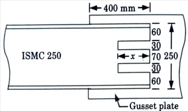
a. A tie member consists of 2 ISMC 250. The channels are connected on either side of a 12 mm thick gusset plate. Design the welded joint to develop the full strength of the tie. However, the overlap is to be limited 400 mm.
Ans. Given: Section = ISMC 250, Thickness of gusset plate = 12 mm, Overlap = 400 mm.
To Find: Design the welded joint.
1. Properties of ISMC 250, are given below:
i. Thickness of web, tw = 7.1 mm
ii. Thickness of flange, tf = 14.1 mm
iii. Sectional area, A = 3867 mm2
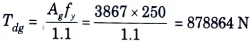
2. Tensile design strength of each channel,
3. Weld thickness :
i. Minimum thickness = 3 mm
ii. Maximum thickness = 7.1 – 1.5 = 5.6 mm
Provide s = 4 mm weld
4. Throat thickness, tt = 0.7 x 4 = 2.8 mm
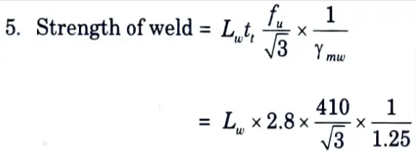
6. Equating the strength of weld to tensile strength of the channel,
we get
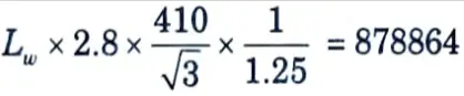
∴ Lw = 1658 mm
7. Since allowable length is limited to 400+ 400 = 800 mm it needs slot weld. The arrangement can be as shown in the Fig. 3 with two slots of length ‘x’ Then
400 + 400 + (250 – 2 x 30) + 4x = 1658
∴ x = 167 mm
(as 2s length of weld will be in effective at each term)
Provide x = 185 mm as shown in Fig. 3.
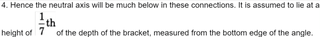
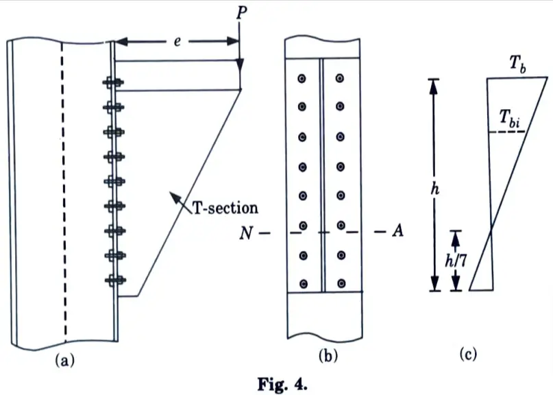
b. How you will be design of bearing bolts subjected to eccentric loading in the plane perpendicular to the groups of bolts.
Ans. 1. This type of connection is shown in Fig. 4. Let P be factored load at an eccentricity ‘e’. Then the section is subjected to a direct shear force P and moment M =P x e.
2. If there are ‘n’ numbers of bolts in the connection, direct design shear force on each bolt is given by,
Vsb = P / n
3. The moment causes tension in top side and compression in the bottom side. On tension side, only bolts resist load but on compression side entire contact zone between the columns and the connecting angle resist the load.
5. The variation of the force is as shown in Fig. 4(c).
The tensile force in a bolt Tbi is proportional to its distance yi from the line of rotation.
Tbi ∝ yi= kyi where k is constant.
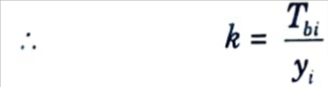
6. Total moment of resistance M provided by bolts in tension.
M’ = ∑Tbi yi = ∑k yi2
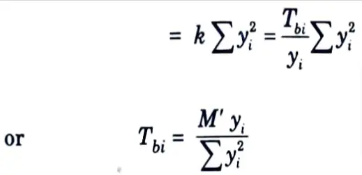
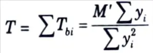
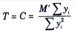
7. Total tensile force in bolts,
8. For equilibrium, total tensile force= total compressive force
9. Taking moment about neutral axis,
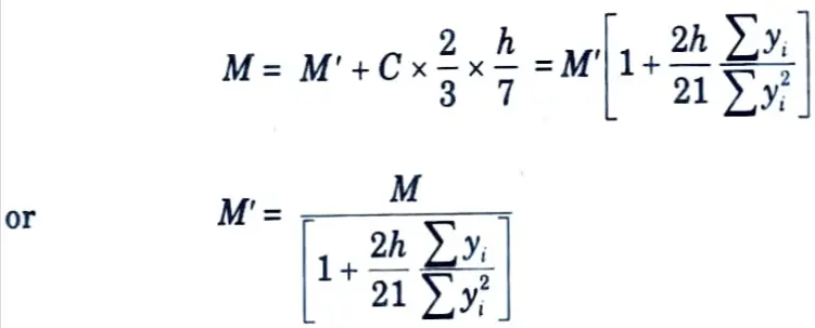
∴ Tensile force Tdb in extreme bolt can be found.
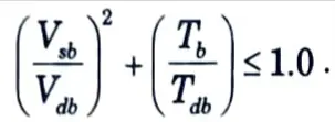
10. This equation gives the moment resisted by the bolts in tension from which the maximum tensile force in the extreme bolt Tb can be calculated. Then the design requirement is
Section 5: Solved Numerical Questions of Design of Steel Structures
a. Define lateral-torsional buckling with neat sketch and also write the assumptions.
Ans. A. Lateral Torsional Buckling :
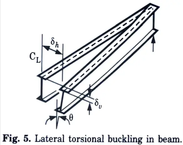
- 1. An unconstrained beam may experience lateral torsional buckling. When the compression flange of a beam is allowed to move laterally and rotate, it is said to be unrestrained.
- 2. Lateral torsional buckling occurs when an applied force causes both lateral displacement and twisting of a part.
- 3. Fig. 5 depicts the lateral displacement and twisting of a beam caused by lateral torsional buckling.
B. Assumption: Following are the assumptions made in lateral torsional buckling :
- 1. The beam is initially undistorted.
- 2. Its behaviour is elastic (no yielding).
- 3. It is loaded by equal and opposite end moments in the plane of the web.
- 4. The loads act in the plane of the web only (there are no externally applied lateral or torsional loads).
- 5. The beam does not have residual stresses.
- 6. Its ends are simply supported vertically and laterally.
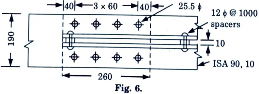
b. A double angle section back-to-back 2 ISA 90 x 90 x 10 is riveted with 24 mm rivets to a 20 mm gusset plate on one side. Determine the section capacity in tension and also the number of rivets required for develop the 85 % tension capacity.
Ans. Given: Member 2 ISA 90 x 90 x 10, Diameter of rivets, d = 24 mm, Thickness of gusset plate, tp = 20 mm.
To Find: Section capacity in tension, Numbers of rivets required to develop 85 % tension capacity.
1. Gross area of the section = 2A = 2 (1703) = 3406 mm²
2. Area of each leg = A1 = A2 = A/2 = 1703/2 = 851 mm²
3. Diameter of rivet hole, dh = 24 + 1.5 = 25.5 mm
4. Assuming a single row of rivets in each angle the net area of the connected leg is
A1n = A1 – dht = 851 – 25.5 (10) = 596 mm2
5. Effective outstand leg ratio for angle back-to-back is
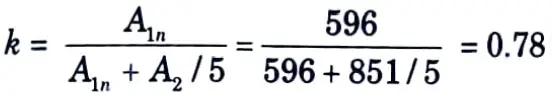
6. Effective area of cross section is
Ae = 2 [A1n + kA2] = 2 (596 + 0.78 x 851]
= 2519.56 mm2
7. Allowable stress in the material under tension is
σat = 150 N/mm² =0.15 kN/mm2
8. Allowable capacity in tension is
Pa = Ae σat = 2519.56 x 0.15 = 378 kN
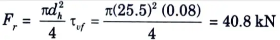
9. The rivets are in single shear and the capacity is controlled by the shear capacity of the hand driven rivet:
10. Number of rivets required
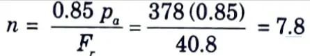
for 85 % capacity of plates.
11. Provide 4 rivets in each angle. The minimum pitch and edge distances for rolled edges are :
p = 2.5d = 60 mm; e =38 mm, say 40 mm
12. Let the gusset plate be flush with the edges, then the width of the plate with 10 mm spacing between angle is
B = 2 (90) + 10 = 190 mm
13. Minimum length of overlap of gusset is
Lp = e + 3p = 2 x 40 + 3 x 60 = 260 mm
14. Capacity of gusset plate with two 25.5 ɸ mm rivet holes is :
T = (B – 2dh) tp σat = (190 – 51) (20) (0.15) = 447 kN
15. Fig. 6 illustrates the joint.
Section 6: Important Numerical Design of Steel Structures
a. Design a built-up column consisting of two channels placed toe-to-toe. The column carries an axial factored load of 1500 kN. The effective height of the column is 10 m. Design the lacing also. Assume Fe 415 grade steel.
Ans. Given: Axial factored load, Pu = 1500 kN, Effective height of column, Le = 10 m, Grade of steel = Fe 415
To Find: Design of built up column, Lacing system.
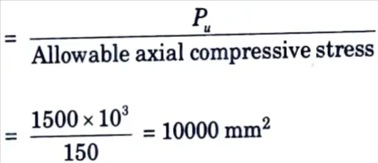
1. Let the design axial compressive stress for the column be 150 MPa Cross-sectional area required
2. Let us try ISMC 400 @ 484.6 N/m section, the relevant properties of ISMC 400@ 484.6 N/m :
i. Area of section = 6293 mm².
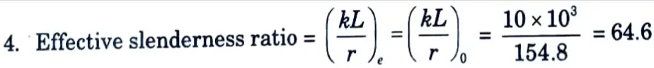
ii. Radius of gyration, rz = 154.8 mm, ry = 28.3 mm
iii. Cyy = 24.2 mm
iv. Moment of inertia, Iz = 15032.8 x 104 mm4, Iy = 504.8 x 104 mm4
3. Area provided = 2 x 6293 = 12586 mm²
6. Design compressive strength,
Pd = Acfcd = 175 x 12586 = 2202550 N
= 2202.55 kN > 1500 kN
Hence safe.
7. Let us provide the two channels toe-to-toe and connect them with lacing.
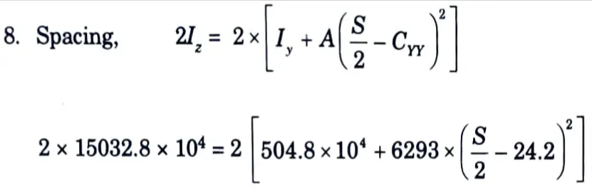
S = 352.3 mm
Let us place the channels at a spacing of 354 mm.
9. Connection System :
i. Provided a single lacing system. Assume the inclination of the lacing bar to 45°
a1 = 2 x (354 – 60 – 60) cot 45°
= 468 mm [∵ g = 60 mm]
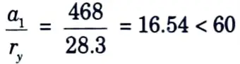
and should also be < 0.7x 64.6= 45.22 which it is
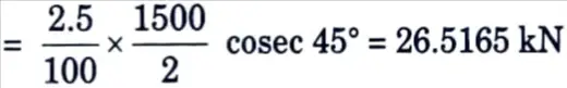
ii. Compressive force in lacing bar,
10. Lacing Flats :
i. Let us provide 16 mm diameter bolts of grade 4.6 for 16 mm diameter bolts.
ii. Minimum width of lacing flat as specified by IS code is 3 x 16 = 48 mm. Let us provide 50 mm wide flats.
iii. Minimum thickness of lacing flat,
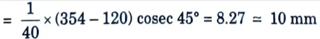
Provide 8 mm thick flat.

Which is safe.
Provide 50 ISF 10 mm flat section.

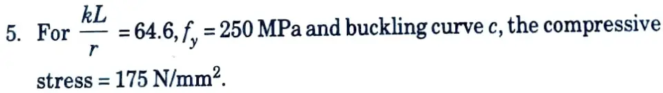
compressive stress, fcd = 83.7 N/mm2
vii. Design compressive strength of flat,
Pd = fcd x Ac
Which is safe.
vi. The tensile strength of lacing flat will be minimum of :
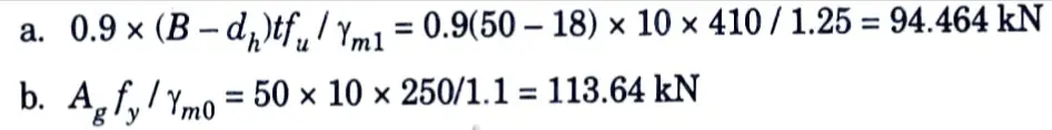
Hence, tensile strength of flat = 94.464 kN > 26.5165 kN
Which is safe.
11. Connection :
i. Strength of 16 mm diameter bolt in double shear = 58.0 kN
ii. Strength of 16 mm diameter bolt in bearing = 2.5 kbdt fu/γmb
= 2.5 x 1.0 x 16 x 10 x 410/ 1.25 = 131.2 kN
Hence, strength of bolt = 58.0 kN

Provide one 16 mm diameter bolt of grede 4.6 for the connection at each end of lacing flat.
12. Tie Plates :
i. Effective depth of tie plate = S – 2Cyy = 354 – 2 x 24.2 = 305.6 mm
ii. Diameter of bolt hole, dn = 16 + 2 = 18 mm
iii. Minimum edge distance = 1.5 x 18 = 27 ≃ 30 mm
iv. Length of tie plate = 354 mm
v. Overall depth of tie plate = 305.6 + 2 x 30 = 365.6 ≃ 370 mm

Provide a tie plate of 354 x 370 x 6 mm.
b. With neat sketches describe failure modes of an axially loaded column.
Ans. The possible failure modes of an axially loaded column are as follows :
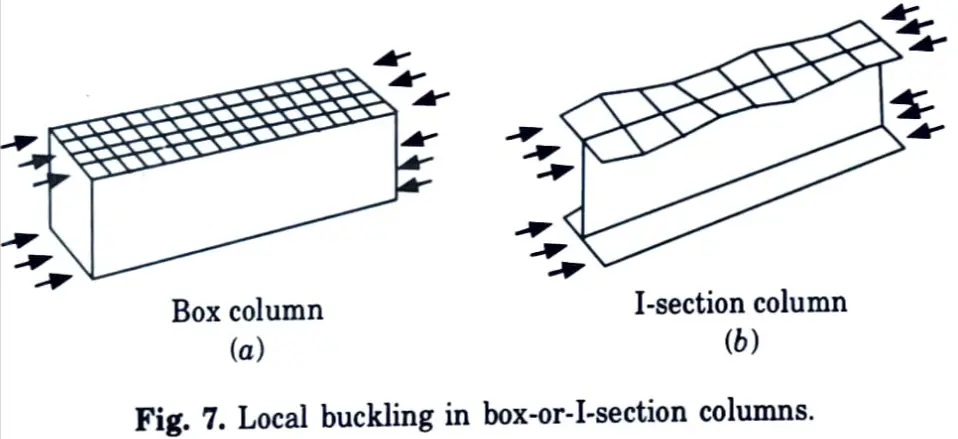
1. Local Buckling :
- i. Failure occurs as a result of buckling of one or more individual plate elements, such as a flange or web, with no overall deflection in the direction normal to the applied stress.
- ii. This failure mode can be avoided by selecting component plates with appropriate width-to-thickness ratios. Conversely, when using thin plates, the design strength may be lowered.
2. Squashing: When the column’s length is relatively short (stocky column) and its component plate parts are protected from local buckling, the column can reach its full strength or squash load’ (yield stress x area of cross section).
3. Overall Flexural Buckling :
- i. Most compression members are designed with this kind of failure in mind. In this mode, the member fails due to severe deflection in the plane of the weaker primary axis.
- ii. As the length of the column increases, the column resists gradually less weights.
4. Torsional and Flexural-Torsional Buckling :
- i. Torsional buckling failure occurs by twisting about the shear centre in the longitudinal axis
- ii. Flexural-torsional buckling, which is a mix of flexure and twisting, is also possible.
- iii. Torsional buckling is a probable failure mode for point symmetric sections.
- iv. Flexural Torsional buckling must be checked for open sections that are singularly symmetric or have no symmetry.
Section 7: Important Derivation Design of Steel Structures
a. Design a simply supported beam of span 3.5 m subjected to a factored bending moment of 300 kN-m and factored shear of 140 kN. The beam is laterally unsupported. Steel grade of Fe 410.
Ans. Given : Span of beam = 3.5 m, Factored bending moment = 300 kN-m, Factored shear force = 140 kN, Grade of speed = Fe 410
To Find: Design of simply supported beam.
Assume: Yield strength, fy = 250 MPa
Yield strength of weld, fyw = 250 MPa
Shear modulus, G = 76.923 x 10³ Nmm2, Partial safety factor for material, γm0 = 1.1
1. Effective span, LLT = kL = 3.5 m
Imperfection factor, λLT = 0.21 (For rolled section)
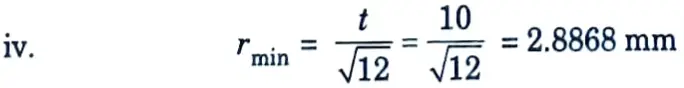
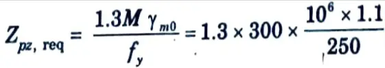
2. Plastic section modulus required,
3. Let us try ISHB 450 @ 855.43 N/m. The relevant properties of section are :
i. Depth of section, h = 450 mm
ii. Width of flange, bf = 250 mm
iii. Thickness of web, tw = 9.8 mm
iv. Thickness of flange, tf = 13.7 mm
v. Radius at root, R1 = 15 mm
vi. Depth of web, d = h – 2(tf + R1) = 450 – 2(13.7 + 15) = 392.6 mm
vii. Moment at inertia, Izz = 39210.8 x 104 mm4, Iyy = 2985.2 x 104 mm4
viii. Plastic section modulus, Zpz = 1955.03 x 103 mm3
ix. Elastic section modulus, Zez = 1743.7 x 103 mm2
4. Section Classification :
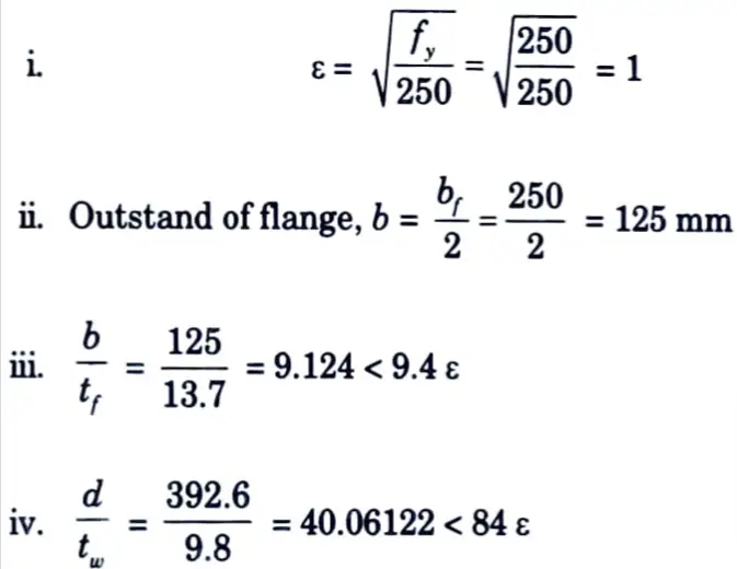
Hence, the section is plastic (βb = 1)
Since d/tw = 40.06122 < 67 ε, shear buckling check of web will not be required.
5. Check for Bending Moment :
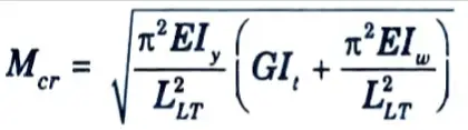
Lateral torsional buckling moment is given by,
i. E = 2 x 10⁵ N/mm2
ii. G = 76.923 x 10³ N-mm2
iii. LLT = kL = 3500 mm
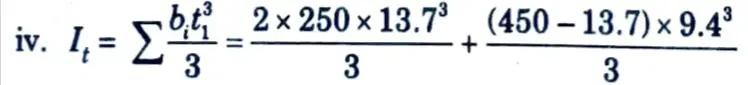
= 549353.433 mm4 =54.9353 x 104 mm4
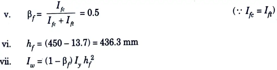
= (1 – 0.5) x 0.5 x 2985.2 x 104 x 436.32
= 1.42 x 1012 mm
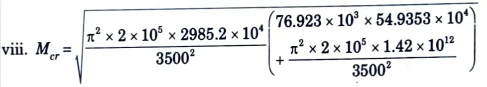
= 1141893302 N-mm = 1141.9 kN-m
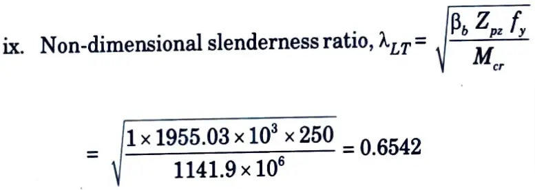
Since λLT is greater than 0.4 the effect of lateral torsional buckling has to be considered
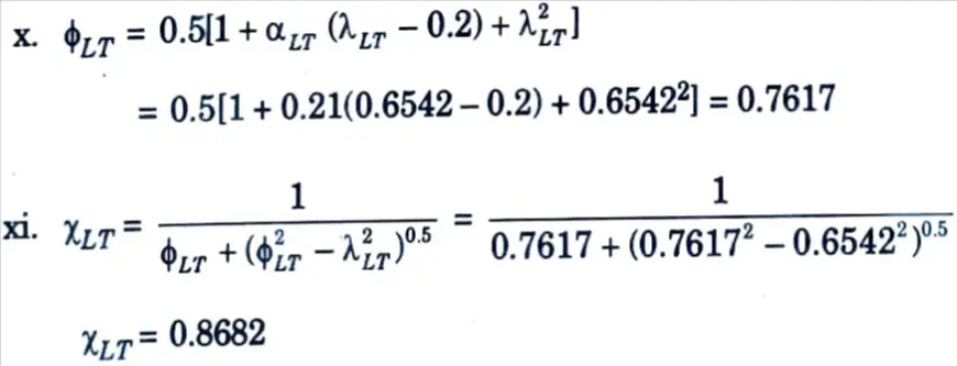
xii. Design bending compressive stress,
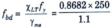
fbd = 197.32 N/mm2
xiii. Design bending capacity,
Md = βbZpzfbd = 1 x 1955.03 x 10 x 197.32
= 385766519.6 N-mm
= 385.766 kN-m > 300 kN-m
Which is all right
6. Check for Shear Capacity :
i. Design shear force, V = 140 kN
ii. Design shear strength of the section,
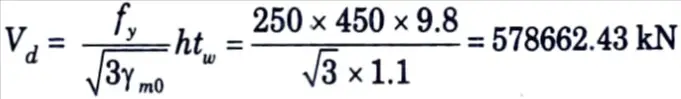
= 578.662 kN > 140 kN
Which is all right
7. Check for Web Bearing :
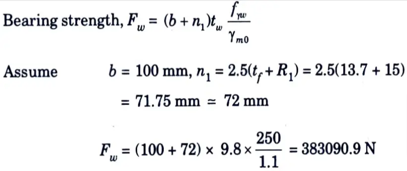
= 383.1 kN > 140 kN
Hence, the design is safe.
b. A simply supported beam of span 4.5 m consist of rolled steel section ISLB 450 @ 640 N/m. The compressive flange is laterally unsupported. Determine the design bending strength of the beam.
Ans. Given: Span of beam, L=4.5 m, Section = ISLB 450 @ 640 Nm
To Find: Design bending strength of the beam
Assume: Grade of steel = Fe410, fy = 250 N/mm2
1. The relevant properties of ISLB 450 @ 640 N/m are :
i. Depth of section, h = 450 mm
ii. Width of flange, bf = 170 mm
iii. Thickness of flange, tf = 13.4 mm
iv. Thickness of web, tw = 8.6 mm
v. Radius at root, R1 = 16 mm
vi. Depth of web, d = h – 2(tf + R1) = 450 – 2(13.4 + 16) = 391.2 mm
vii. Moment of inertia, Iz = 27526.1 x 104 mm4, Iy = 853 x 104 mm4
viii. Plastic section modulus, Zpz = 1401.35 x 103 mm3
ix. Elastic section modulus, Zez = 1223.8 x 103 mm3
x. Radius of gyration, gy = 32 mm
2. Section Classification :

ii. Outstand of flange, b = bf / 2 = 170/2 = 85 mm
iii. b/tf = 85 / 13.4 = 6.343 < 9.4 ε
iv. d/tw = 391.2 / 8.6 = 45.49 < 84 ε
Hence the section is plastic (βb = 1)
Since d/tw = 45.49 < 67 ε. Check for web buckling will not be required.
3. Design Moment Calculations :
i. Elastic modulus of steel, E = 2 x 10⁵ N/mm2

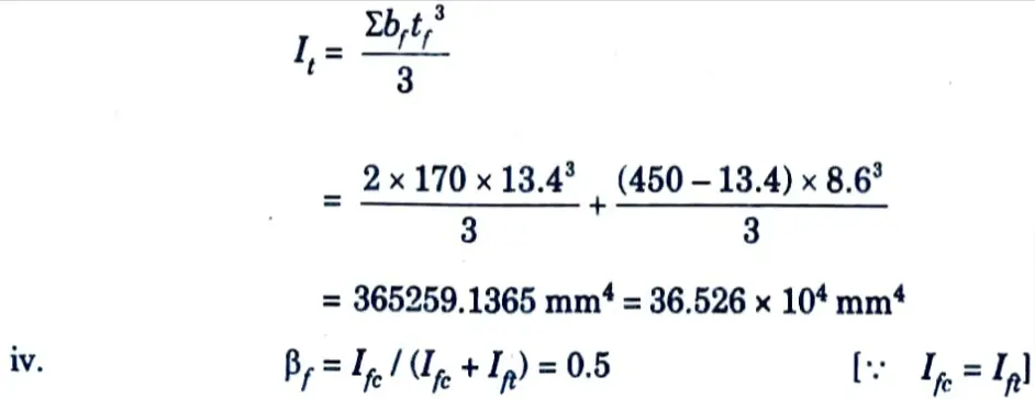
iii. St. Venant constant,
v. c/c distance between flanges,
hf = 450 – tf = 450 – 13.4 = 436.6 mm
vi. Warping constant,
Iw = (1 – βf)βfIyhf2
= 0.5 x 0.5 x 853 × 104 x 436.62 = 4.065 x 1011 mm6
vii. Lateral torsional buckling moment,
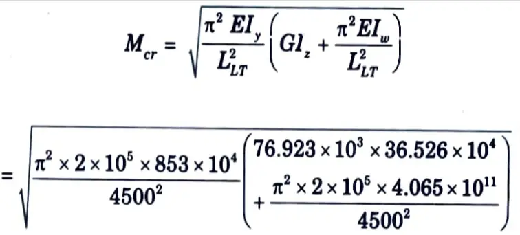
= 237295908.2 N-mm = 237.296 kN-m
viii. Non dimensional slenderness ratio,
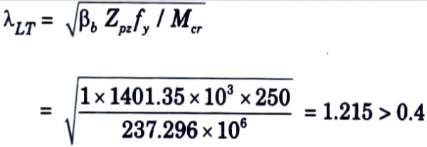
Since λLT > 0.4, the effect of lateral torsional buckling has to be considered.
ix. Imperfection factor, αLT = 0.21
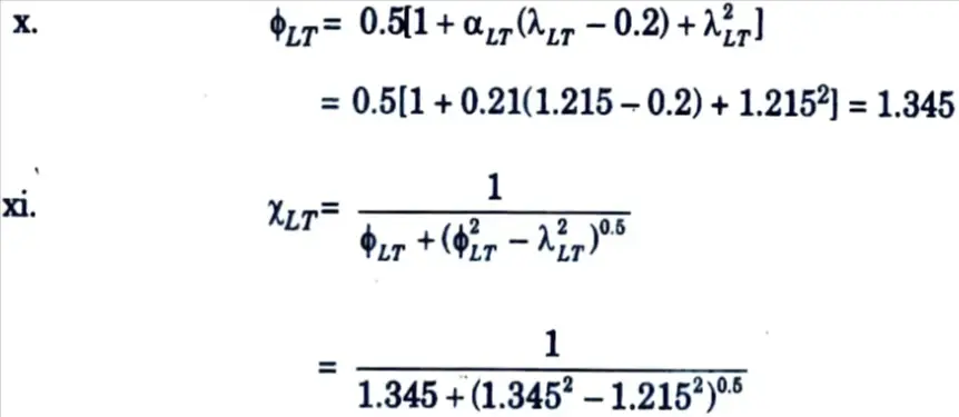
= 0.5203
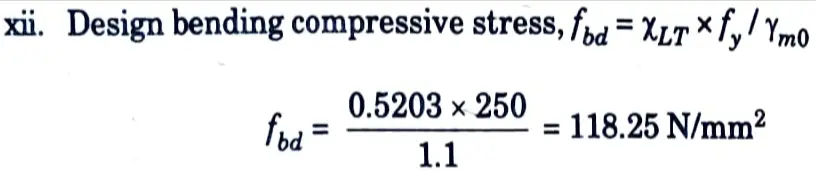
xiii. Design bending capacity,
Md = βbZpzfbd = 1 x 1401.35 x 103 x 118.25
= 165709637.5 N-mm
= 165.71 kN-m
2 thoughts on “Design of Steel Structures: AKTU Solved Question Paper”