
AKTU Solved Question Paper provides thorough resources for thorough test preparation in the area of electric drives. You can choose the appropriate topics for efficient exam preparation by using the offered answers to the questions to improve your understanding of ideas, practise problem-solving, and practise problem-solving.
Dudes 🤔.. You want more useful details regarding this subject. Please keep in mind this as well.

Important Questions For Electric Drives:
*Quantum          *B.tech-Syllabus
*Circulars           *B.tech AKTU RESULT
* Btech 4th Year
Section A: Short Question Electric Drives
a. What are the disadvantages of DC drives ?
Ans.
- 1. The commutator adds bulk, cost, and weight to the motor. Sparking at the brushes renders it environmentally inappropriate in some areas.
- 2. The line conditions are very poor, i.e., poor power factor.
b. Why electric drive is preferred over mechanical drive ?
Ans. Electric drives are favoured over mechanical drives because they have the advantages of quick start, strong torques, and relatively trouble-free operation.
c. What is meant by classes of duty of motor ?
Ans. Electric drives are used to control the electric motors. However, not all motors have the same operational time. Some motors operate continuously, while others run for a shorter period of time than the rest interval. Based on this, the notion of motor duty class is introduced, and motor duty cycles can be classified into eight groups.
Different classes of motor :
- 1. Continuous duty.
- 2. Short time duty.
- 3. Intermittent periodic duty.
- 4. Intermittent periodic duty with starting.
- 5. Intermittent periodic duty with starting and braking.
- 6. Continuous duty with intermittent periodic loading.
- 7. Continuous duty with starting and braking.
- 8. Continuous duty with periodic speed changes.
d. What are the problems faced in case a motor of wrong rating is chosen ?
Ans. If a motor of wrong rating is chosen, the problems faced are:
- i. It fails to drive the load at its usual productive level or reduces productivity and reliability due to frequent damage and shutdowns caused by motor and power modulator overloading.
- ii. The additional initial cost and energy loss from operating at less than rated power make the choice uneconomical.
e. What do you mean by acceleration time of three phase induction motor ?
Ans. It is the time required for the motor to accelerate the stipulated load inertia at the specified voltage.
f. What is the most economical method of electric braking ?
Ans. The most economical method of electric braking is regenerative braking.
g. Why the thyristor control is preferred over Ward Leonard system of speed control ?
Ans. Thyristor control entails of the following advantages over Ward Leonard system of speed control :
- i. Highly reliable.
- ii. Easy maintenance.
- iii. Cost of installation is low.
- iv. Floor space requirement is low.
- v. Operation accuracy is higher.
h. How you can change speed of separately excited DC motor.
Ans. Speed of a separately excited DC motor can be changed in the following ways :
- 1. Adjusting the field resistance, Rf.
- 2. Adjusting the terminal voltage applied to the armature.
- 3. Inserting a resistor in series with armature circuit.
i. What are the disadvantages of DC drives due to which the three phase induction motor is replacing it ?
Ans.
- 1. The commutator makes the motor bulky, costly and heavy. Sparking at the brushes makes it environmentally unsuitable in certain locations.
- 2. The highest speed and design rating are limited due to commutation.
- 3. The commutator requires frequent maintenance.
- 4. The converter technology is well established. The power converter is simple and inexpensive.
j. What do you understand by the steady state stability ?
Ans. Steady-state stability: It is assumed that speed and torque deviations follow the steady-state speed-torque curves of the motor and load. Because the changes are so slow, the energy storage elements have little effect on the variation as it moves from one state of equilibrium to the next. When a motor is slowly or progressively loaded, it can be loaded to its maximum torque or power capacity.
Section B: Long Question of Electric Drives
a. In which type of applications four quadrant operation is employed in industries ? Explain in detail the working of such an electric drive.
Ans.
- 1. A motor operates in two modes-motoring and braking.
- 2. In motoring, it converts electrical energy to mechanical energy, which support its motion.
- 3. In braking it works as a generator converting mechanical energy to electrical energy, and thus opposes the motion.
- 4. Motor can provide motoring and braking operations for both forward and reverse directions.
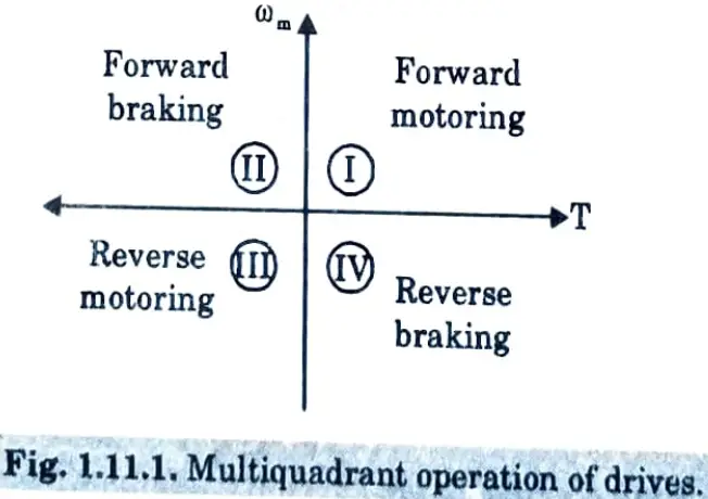
- 5. Fig. 1.11.1 shows the torque and speed coordinates for both forward and reverse motions.
- 6. The product of speed and torque gives the power developed by a motor.
- 7. The developed power in quadrant I is positive. As a result, the machine functions as a motor, supplying mechanical energy. Forward motoring refers to operation in quadrant I.
- 8. Power is negative in quadrant II. As a result, the machine functions by braking against the momentum. As a result, operation in quadrant II is referred to as forward braking.
- 9. Similarly, operations in quadrants Il and IV are reverse motoring and braking, respectively.
In hoist type load, four quadrant operation is employed.
b. Discuss the dynamics of motor load system and also derive the relations for motor- load torque system.
Ans. 1. A motor generally drives a load through some transmission system. As the motor rotates, the load may rotate or may undergo a translational motion.
2. It is convenient to represent the motor-load system by an equivalent rotational system.
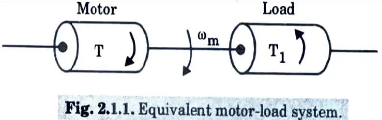
3. Various notations used are :
J = polar moment of inertia of motor-load system referred to the motor shaft, kg-m2.
ωm = instantaneous angular velocity of motor shaft, rad/sec.
T = instantaneous value of developed motor torque, N-m.
Tr = instantaneous value of load (resisting) torque, referred to motor shaft, N-m.
4. Load torque includes friction and windage torque of motor.
Motor-load system of Fig. 2.1.1 can be described by the following fundamental torque equation :
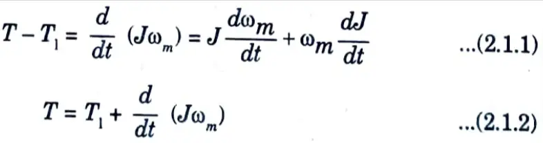
Eq. (2.1.2) shows that torque developed by motor is counter balanced by a load torque T1 and a

5. Drive accelerates or decelerates depending on whether T is greater or less than T1. During acceleration motor should supply not only the load torque but an additional torque component
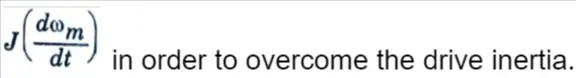

assists the motor developed torque T and maintains drive motion by extracting energy from stored kinetic energy.
c. A 220 V, 800 rpm, 60A DC separately excited motor has an armature resistance of 0.09 Ω. It is broken by plugging from an initial speed of 1500 rpm. Calculate (i) Resistance to be placed in armature circuit to limit braking current to twice the full load value (ii) Braking torque (iii) Torque when the speed has fallen to zero.
Ans. i. Resistance, RB = 5.09 Ω
ii. Braking torque,
T = 307.38 N-m
iii. Torque when speed has fallen to zero
T = 108.78 N-m
d. Explain chopper controlled DC motor drive in detail.
Ans. 1. A transistor chopper controlled separately excited motor drive is shown in Fig. 4.18.1(a).
2. Transistor Tr is operated periodically with period T and remains ON for a duration tON.
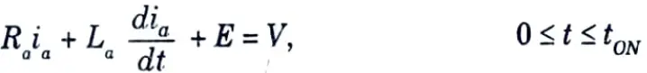
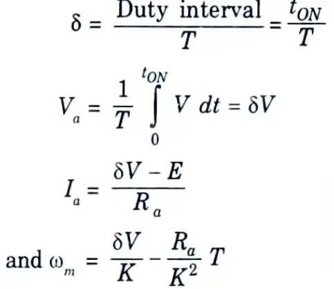
3. Waveforms of motor terminal voltage va and armature current ia for continuous conduction are shown in Fig. 4.18.1(b). During ON period of the transistor, 0 ≤ t ≤ tON the motor terminal voltage is V. The operation is described by
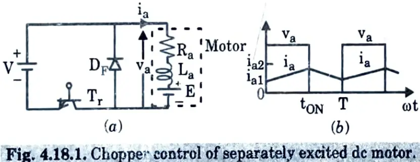
4. In this interval, armature current increases from ia1 to ia2. Since, motor is connected to the source during this interval, it is called duty interval.
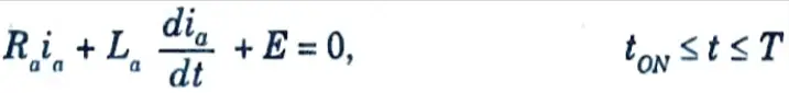
5. At t = tON Tr is turned off. Motor current freewheels through diode DF and motor terminal voltage is zero during interval tON ≤ t ≤ T.
Motor operation during this interval, known as freewheeling interval is described by
Motor current decreases from ia2 to ia1 during this interval.
Ratio of duty interval tON to chopper period T is called duty ratio or duty cycle (δ). Thus,
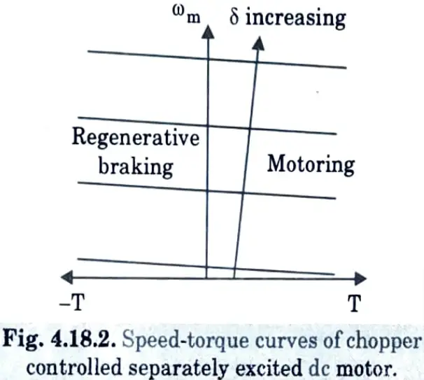
The nature of speed-torque characteristic is shown in Fig. 4.18.2.
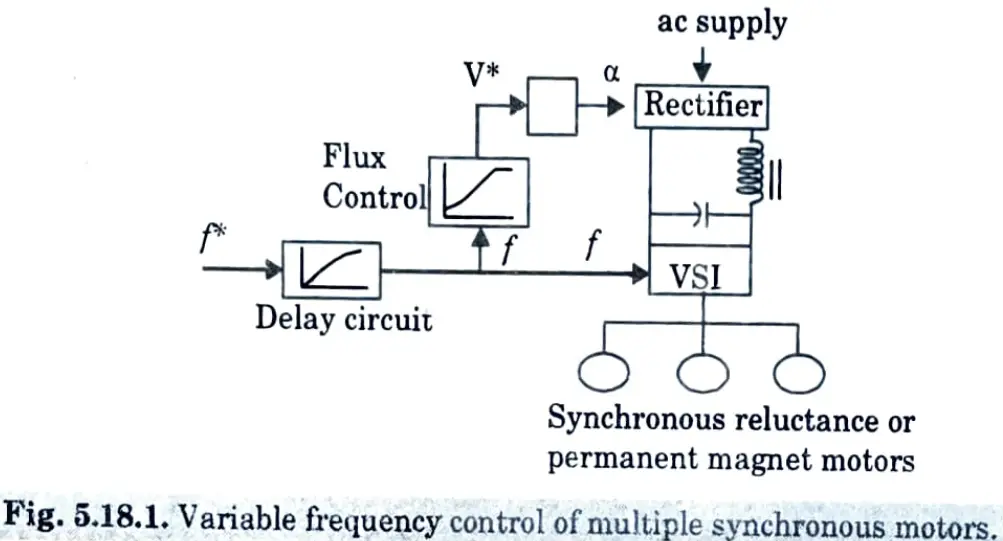
e. What is the basic difference between true synchronous mode and self control mode for variable frequency control of synchronous motor ?
Ans. Variable frequency control :
- 1. Synchronous speed is directly proportional to frequency.
- 2. Motor speed can be controlled by varying the frequency.
- 3. Constant flux operation below base speed is achieved, as with an induction motor, by operating the motor with a constant (V/f) ratio, which is increased at low speeds to compensate for stator resistance loss.
- 4. For higher speeds, the machine is run at a rated terminal voltage and variable frequency, with the pull-out torque decreasing as the frequency increases.
- 5. Variable frequency control may employ any of the two modes :
- i. True synchronous mode
- ii. Self-controlled mode, also known as self-synchronous mode.
- 6. The stator supply frequency is controlled by a separate oscillator in full synchronous mode. The frequency is gradually increased from its beginning value to the desired value, ensuring that the discrepancy between synchronous speed and rotor speed is always modest. This enables the rotor speed to track variations in the synchronous speed.
- 7. After hunting oscillations, the rotor pulls into step when the necessary synchronous speed (or frequency) is obtained. Variable frequency control can be used for more than just speed control; it can also be used for smooth starting and regenerative braking, as long as the frequency changes are gradual enough for the rotor to detect changes in synchronous speed. For pull-in to synchronism, a motor with damper winding is utilised.
- 8. In self-control mode, the stator supply frequency is adjusted so that the synchronous speed equals the rotor speed. This ensures that the rotor runs at the same speed at all operational positions. As a result, the rotor is unable to pull-out for step, and hunting oscillations are removed. A damper winding may not be required for such applications.
- 9. In self-control mode, the stator supply frequency is varied in proportion to the rotor speed, ensuring that the stator’s rotating field always rotates at the same speed as the rotor (or rotor field).
- 10. Because the voltage induced in the stator phase has a frequency proportionate to the rotor speed, self-control can be achieved by adjusting the stator supply frequency to follow the frequency of the induced voltage.
Section 3: Questions With Diagram in Electric Drives
a. Draw the block diagram of an electric drive. Explain the function of power modulator in detail.
Ans. A. Block diagram of an electric drive :
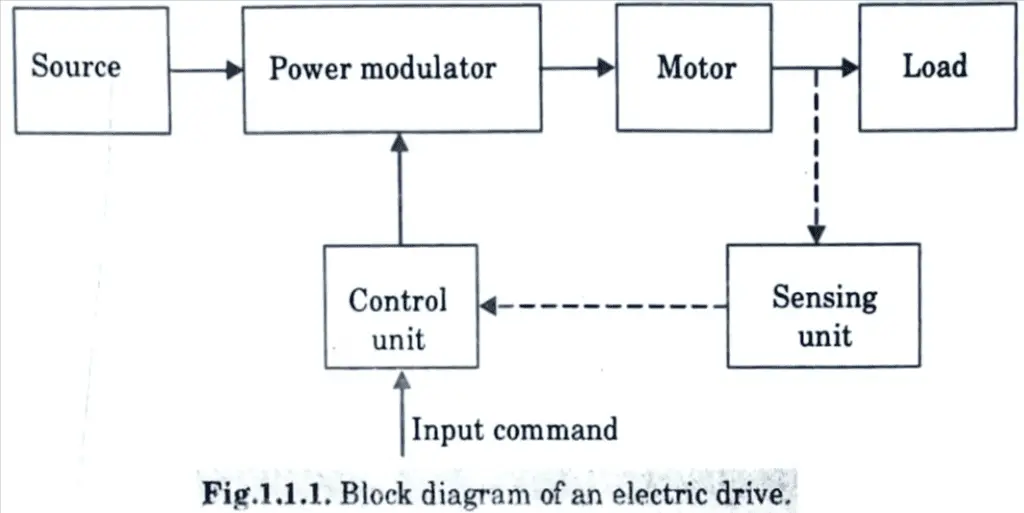
B. Function of power modulator :
- 1. It limits source and motor current during transient operation, such as starting, braking, and speed reversal; excessive current drawn from the source may overload it or produce a voltage dip.
- 2. Modulates power flow from the source to the motor such that the motor receives the speed-torque characteristics required by the load.
- 3. Converts electrical energy from the source into a form suitable for motor operation; for example, if the source is dc and an induction motor is to be used, the power modulator must convert dc to variable frequency ac.
- 4. Selects the mode of operation of the motor.
b. Give the advantages of electric drives over mechanical drive; explain each advantage with respect to industrial application.
Ans. Advantages of electric drives are :
- 1. They have adaptable control properties. Electrical drives’ steady-state and dynamic characteristics can be adjusted to meet load requirements. Speed can be adjusted in a variety of ways. Electronic braking is an option. Control gear for speed control, starting, and braking is often basic and straightforward to use.
- 2. They have a wide range of torque, speed, and power.
- 3. Electric motors are highly efficient, have low no-load losses, and can handle significant short-term overloading. They can be built in a variety of designs to be load suitable. They have a longer life, lower noise, less maintenance requirements, and a cleaner operation when compared to other prime movers.
- 4. They may be used in practically any operational environment, including explosive and radioactive environments submerged in liquids, vertical mountings, and so on.
- 5. Avoid polluting the environment.
- 6. Capable of operating in all four quadrants of the speed-torque plane.
- 7. Unlike other prime movers, the motor does not need to be refuelled or warmed up. They can be started instantaneously and fully loaded immediately.
They are propelled by electricity. It can be produced and transported to the desired location in a cheap and effective manner. Electrical energy can be converted to mechanical energy and vice versa, as well as electrical energy from one form to another, in an efficient and cost-effective manner.
Section 4: Briefly Discussed Questions in Electric Drives
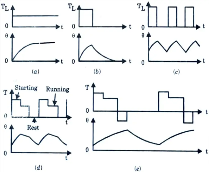
a. Explain the loading of an electric motor and its duty cycle with a simple diagram.
Ans. Different classes of motor duty are :
1. Continuous duty (Fig.(a)):
- 1. It describes the operating of a motor at a constant load torque for a long enough period of time for the motor temperature to reach a steady-state value.
- 2. This duty is distinguished by persistent motor loss.
- 3. Examples of continuous duty are paper mill motors, compressors, conveyers, centrifugal pumps, and fans.
2. Short time duty (Fig.(b)) :
- 1. The time of drive operation is significantly less than the heating time constant in this case, and the machine is permitted to cool to room temperature before the motor is required to function again.
- 2. During this process, the machine can be overloaded until the temperature at the end of the loading reaches the allowable limit.
- 3. Examples are crane drives, drives for household appliances, turning bridges, sluice-gate drives, etc.
3. Intermittent periodic duty (Fig.(c)) :
- 1. It is made up of periodic duty cycles, each of which comprises of a time of constant load operation followed by a period of rest.
- 2. Neither the running period nor the rest period are long enough to elevate the temperature to a steady-state value and allow the machine to cool to ambient temperature.
- 3. The heating of the machine during starting and braking activities is negligible in this case. Drives for pressing, cutting, and drilling machines are examples.
4. Intermittent periodic duty with starting (Fig.(d)) :
- 1. Heat losses during starting must not be overlooked.
- 2. It consists of a starting phase, a time of operation at a constant load, and a rest period, with the operating and rest periods being too short to achieve the corresponding steady-state temperatures.
- 3. When mechanical brakes are employed for stopping or the engine is allowed to stop owing to its own friction, heating of the machine while braking is regarded minimal.
- 4. Examples are metal cutting and drilling tool drives, drives for fork lift trucks, etc.
5. Intermittent periodic duty with starting and braking (Fig.(e)):
- 1. Here, heat losses during starting and braking cannot be ignored.
- 2. It comprises of a starting phase, a constant load operation period, an electrical braking time, and a rest period, with the operating and rest periods being too short to achieve the corresponding steady-state temperature.
- 3. Examples are billet mill drive, manipulator drive, ingot buggy drive, etc.
6. Continuous duty with intermittent periodic loading :
- 1. It consists of periodic duty cycles, each consisting of a period of constant load operation and a period of no load operation with normal voltage across the excitation winding.
- 2. This duty differs from intermittent periodic duty in that a time of running at a constant load is followed by a period of running at no load rather than rest.
- 3. Examples are pressing, cutting, shearing and drilling machine drives.
7. Continuous duty with starting and braking :
- 1. It is made up of periodic duty cycles, each including a starting period, a running period at a constant load, and an electrical braking time. Example is drive of a blooming mill.
8. Continuous duty with periodic speed changes: It is made up of periodic duty cycles, each of which has a period of running at one load and speed and another period of running at a different load and speed. Also, there is no downtime.
b. What is heating time constant ? Explain how the rating of motor is affected by the temperature rise of electric motor.
Ans. Heating time constant :
1. Let the machine, which is assumed to be homogenous body, and the cooling medium has following parameters at time t.
p1 = heat developed, joules/sec or watts.
p2 = heat dissipated to the cooling medium, joules/sec or watts.
W = weight of the active parts of machine, kg.
h = specific heat, joules per kg per °C.
A = cooling surface, m2.
d = coefficient of heat transfer or specific heat dissipation, joules/sec/m2/°C.
𝜃 = mean temperature rise, °C.
2. During a time increment dt, let the machine temperature rise be d𝜃.
Since,
Heat absorbed (or stored) in the machine = (Heat developed inside the machine -Heat dissipated to the surrounding cooling medium)
or Wh d𝜃 = p1dt – p2dt ….(2.11.1)
∵ p2 = 𝜃dA ….(2.11.2)
Substituting in eg. (2.11.1) and rearranging the terms
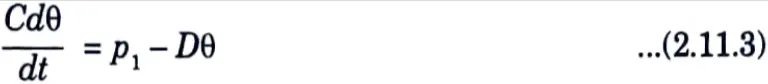
where, C = Wh …(2.11.4)
and D = dA …(2.11.5)
where, C = thermal capacity of machine, watts/°C.
D = heat dissipation constant, watts/°C.
3. The first order differential eq. (2.11.3) has solution
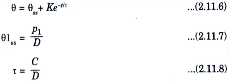
Constant of integration K is obtained by substituting the temperature rise at t =0 in eq. (2.11.6). When the initial temperature rise is 𝜃, eq. (2.11.6) has the solution of
𝜃 = 𝜃SS (1 – e-t/τ) + 𝜃1e-t/τ …(2.11.9)
𝛕, which has the dimension of time is called heating (or thermal) time constant of the machine.
1. Let us consider a simple intermittent load, where the motor is alternatively subjected to a fixed magnitude load Pr‘ of duration tr and standstill condition of duration tS (Fig. 2.23.1).
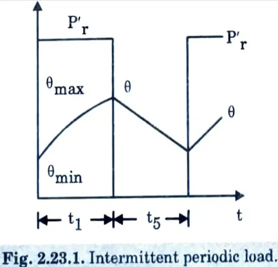
2. As the motor is subjected to a periodic load, after the thermal steady-state is reached the temperature rise will fluctuate between maximum value 𝜃max and minimum value 𝜃min.
3. For this load the motor rating should be selected such that 𝜃max ≤ 𝜃per, where 𝜃per is the maximum permissible temperature rise of the motor.
4. Temperature at the end of working interval is given by
𝜃max = 𝜃SS (1 – e-tr/τr) + 𝜃mine-tr/τr …(2.23.1)
and fall in temperature rise at the end of standstill interval ts will be
𝜃min = 𝜃max e-ts/τs …(2.23.2)
where, 𝛕r and 𝛕s are the thermal time constants of motor for working and standstill intervals. Combining eq. (2.23.1) and (2.23.2)
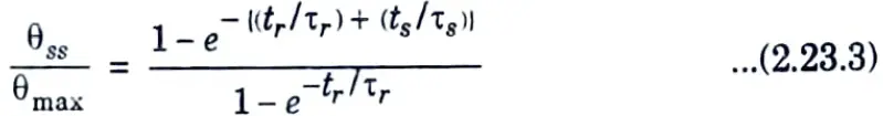
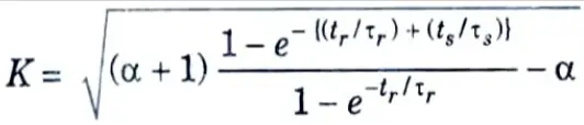
5. For full utilisation of motor, 𝜃max = 𝜃per.
Further if the losses for load values Pr and Pr‘ be denoted by p1r and p1s, then
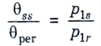
6. ∴ The overloading factor K = (Pr’/Pr) is given by
Section 5: Numerical Questions in Electric Drives
a. Explain reverse voltage braking of a three phase induction motor drive; also give the speed-torque curve for it.
Ans. Plugging or Reverse Voltage braking :
1. When the supply phase sequence of a motor running at a speed is reversed by switching the connections of any two phases of the stator with regard to the supply terminals, the operation moves from motoring to plugging, as shown in Fig.
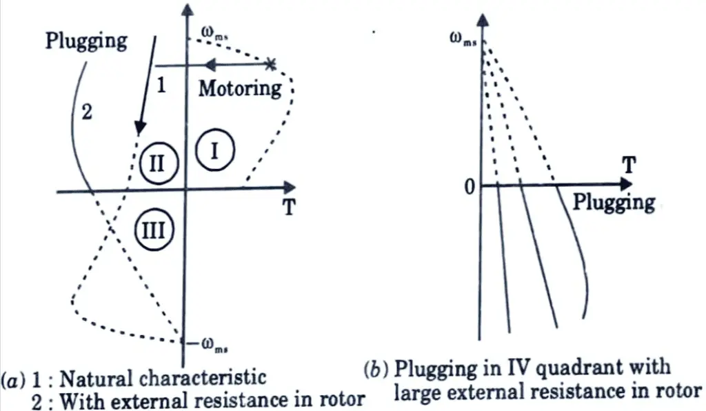
2. Plugging characteristics are actually extension of sequence reverses the negative phase sequence from quadrant III to II. Reversal of phase sequence reverses the direction of rotating field.
3. If the slip for plugging is denoted by sn, then.
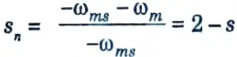
4. Motor performance can be calculated when s is replaced by sn or (2 – s). Since at the instant of switchover to plugging, slip can be upto 2, the rotor induced voltage can be twice of its value at zero speed. Consequently, motor current is large, although braking torque is low. 5. In case of wound-rotor, to limit braking current to starting value.
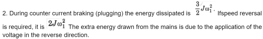
6. This method involves converting mechanical energy into electrical energy and wasting it in the rotor resistance. Mechanical energy is provided to the rotor in this method either by an active load or through kinetic energy stored in the inertia of the motor and load. Rotor resistance consumes additional energy from the source.
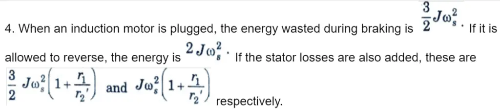
b. Derive the expression to calculate the energy loss during starting of induction motor and also state the various methods used to reduce the energy loss during starting.
Ans. Energy loss during starting: To carry out the design of the brake equipment satisfactorily in conventional ways of braking, such as rheostatic braking and plugging, it is required to determine the energy spent.
1. When a shunt motor is braked dynamically using a resistance the energy dissipated in the resistance is equal to the KE of the motor.
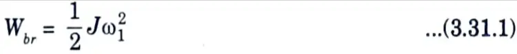
where, J is the moment of inertia. ω1 is the speed at which the braking is initiated.
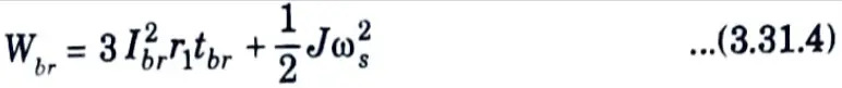
3. For a 3-ɸ induction motor which is braked by dc in the stator
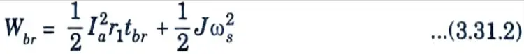
where, tbr is the braking time, which can be estimated from the dynamics of the motor during braking as
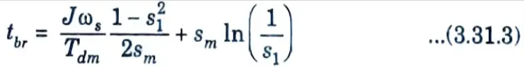
where, s1 is the slip at the instant of braking.
Knowing the various torques occurring in the motor during dynamic braking, the dynamic behaviour of the motor can be established.
The following methods are commonly used to reduce the loss in energy during starting of motors :
- 1. Reducing the moment of inertia of the rotor.
- 2. Starting of dc shunt motors by smooth adjustment of applied voltage.
- 3. Starting of multispeed induction motors in discrete steps of speed.
- 4. Starting of induction motors by smooth variation of supply frequency (V/f control).
1. Reducing the Moment of Inertia of Rotor :
- 1. Reducing the moment of inertia of the drive system reduces overall energy loss in motors during transient operation.
- 2. To achieve this decrease, a single motor with a specific power rating can be replaced by two motors with half the rating.
- 3. As a result of this adjustment, motors with smaller diameters and hence lower moments of inertia will be used.
- 4. Another approach is to employ specifically built motors with a long axial length. These motors will have a smaller diameter than general purpose motors for the same power rating and rotational speed.
2. Starting of de Shunt Motors by Smooth Variation of Applied Voltage :
- 1. This method necessitates the presence of a variable direct voltage source.
- 2. Smooth adjustment of applied voltage is equivalent to applying the voltage in a large number of small voltage steps.
- 3. Let us assume, for easiness sake, that the motor is on no load and develops a constant torque so as to ensure uniform acceleration of the rotor. Starting in steps assumes the presence of a number of discrete steps in speed like ω01, ω02, ω03,… and the starting process to take place from 0 to from 0 to ω01 from ω01 to ω02, from ω03 to ω02 and so on upto the no load speed of the motor ω0. Since the speed of dc shunt motor is approximately directly proportional to applied voltage, the steps in speed will be of equal magnitude, if the voltage is varied in equal steps. Therefore, the loss in energy during starting with m equal steps of voltage can be expressed as
From above equation it is obvious that larger the steps in voltage less will be the energy loss during starting.
3. Starting of Multispeed Induction Motors in Discrete Steps :
Pole-changing motors with two or more speed ratios can be started in separate speed steps. Because the expression for energy loss during starting of an induction motor does not differ from that of a dc shunt motor, it is simply reasoned that this way of starting a multispeed induction motor will also require only reduced energy loss at starting.
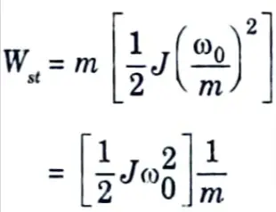
4. Starting of Induction Motors by Smooth Variation of Supply Frequency :
This method will involve changes in speed in a very large number of steps. If the speed steps are equal in magnitude and a large number of steps in frequency are affected, the loss in energy during starting will be given by the expression
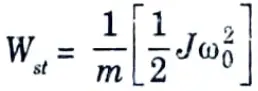
where, ω0 is the final speed achieved by the motor.
Section 6: Repeated Questions in Electric Drives
a. Draw the necessary circuit diagram and waveforms and explain the working of 3-phase converter fed DC motor drive with continuous conduction only. Derive the average O/P voltage with motor load.
Ans. 1. The figure shown below is of a 6-pulse rectifier fed separately excited de motor drive Fig. 4.8.1.
2. Thyristors are fired in the sequence of their numbers with a phase difference of 60° by gate pulses of 120° duration.
3. Each thyristor conducts for 120° and two thyristors conduct at a time one from upper group and other from lower group applying respective line voltage to the motor.
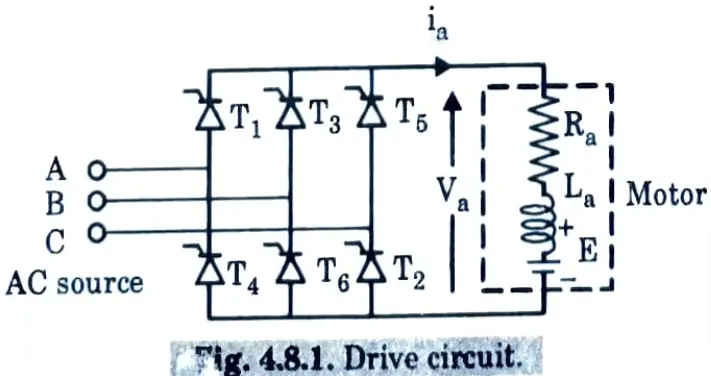
When the relevant line voltage is of such polarity that it not only forward biases the incoming thyristor, but also leads to the reverse biassing of the outgoing when the incoming switches ON, current can be transferred from an outgoing to an incoming thyristor.
4. Thus, firing angle for a thyristor is measured from the instant when the respective line voltage is zero and increasing. For example, the transfer of current from thyristor T5 to thyristor T1 can occur as long as the line voltage vAC is positive. Hence, for thyristor T1, firing angle 𝛼 is measured from the instant vAC = 0 and increases as shown in Fig. 4.8.2 and 4.8.3
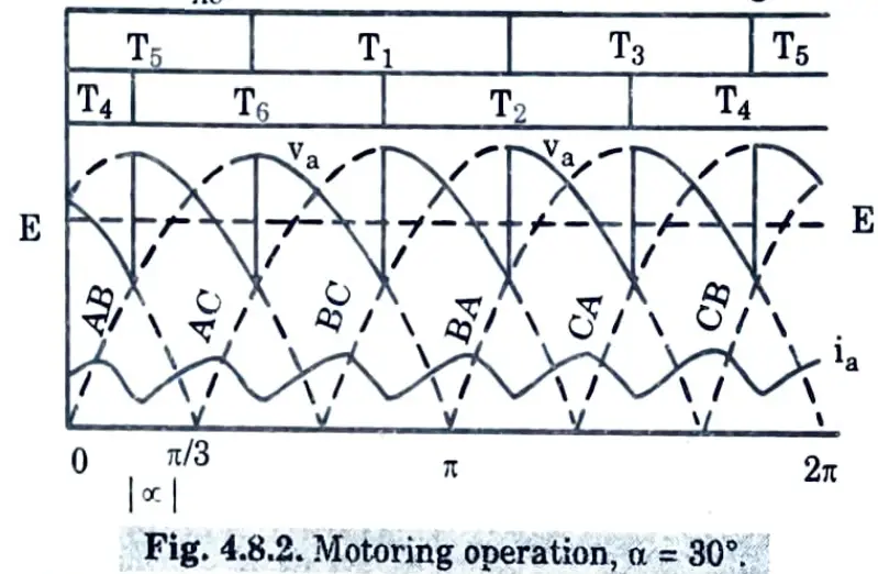
If the line voltage vAB is taken as the reference voltage, then
vAB = Vm sin ωt
𝛼 = ωt – 𝛑/3
where, Vm is the peak of line voltage.
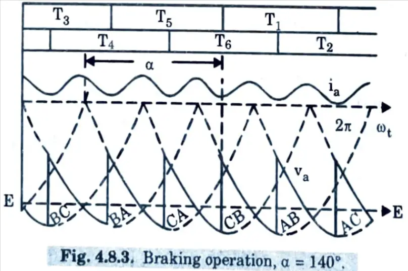
5. Motor terminal voltage and current waveforms are shown in Fig. 4.8.2 and Fig. 4.8.3 for motoring and braking operation respectively.
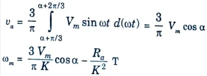
For the motor terminal voltage cycle from (𝛼 + 𝛑/3) to (𝛼 + 2𝛑/3).
b. A 230 volts, 1400 rpm, 20 amps separately excited DC motor has an armature resistance of 15 Ω. It is fed from a single phase fully controlled bridge rectifier with an AC source voltage of 220 volts, at 50 Hz. Assuming continuous load current, compute:
i. The motor speed at firing angle of 40 degrees and torque of 6 N-m.
ii. Developed torque at the firing angle of 40 degrees and speed of 1400 rpm.
Ans. 1. The voltage equation of separately excited DC motor,
Vt = Ea + Ia Ra
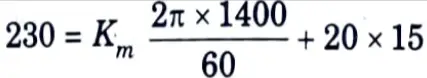
Motor constant,
Km = -0.477 N-m/A
2. For a torque of 6 N-m, motor armature current,
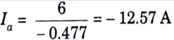
3. The equation giving the operation of converter-motor is
V0 = Vt = Ea + Ia Ra
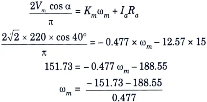
ωm = – 713.37 rad/sec
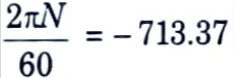
N = – 6808.64 rpm
4. For 𝛼 = 40°
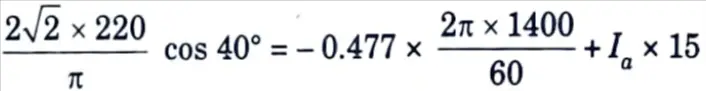
151.73 = – 69.93 + Ia x 15
Ia = 14.77 A
Te = Km x Ia
= – 0.477 x 14.77
= – 7.04 N-m
Section 7: Electrical Engineering Questions of Electric Drives
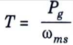
a. Explain how the static scherbius drive is used in slip power recovery scheme.
Ans. 1. This drive provides speed control of wound rotor motor below synchronous speed.
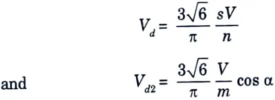
2. A portion of rotor ac power is converted into de by a diode bridge. The controlled rectifier working as an inverter converts it back to the ac source. Power fed back (i.e., Pv) can be controlled by controlling inverter counter emf Vd2, which in turn is controlled by controlling the inverter firing angle.
3. The dc link inductor is provided to reduce ripple in dc link current Id. Since, slip power is fed back to the source, drive has high efficiency.
4. Drive input power is the difference between motor input power and the power fed back. Reactive input power is the sum of motor and inverter reactive powers. Therefore, drive has a poor power factor throughout the range of its operation. From Fig. 5.13.1(a)
where, 𝛼 is the inverter firing angle.
5. n and m are the stator to rotor ratio turns of motor and source side to converter side turns ratio of the transformer respectively. Neglecting drop across inductor
Vd1 + Vd2 = 0
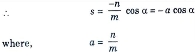
Maximum value of 𝛼 is restricted to 165° for safe commutation of inverter thyristors. Slip can be controlled from 0 to 0.966a when 𝛼 is changed from 90° to 165°. By appropriate choice of a, required speed range can be obtained.
6. Transformer is used to match the voltages Vd1 and Vd2. At the lowest speed required from the drive, Vd1 will have the maximum value Vd1m given by
Vd1m = Vsmax/n
where, smax is the value of slip at the lowest speed. If 𝛼 is restricted to 165°, m is chosen such that the inverter voltage has value Vd1m when 𝛼 is 165°, i.e.,
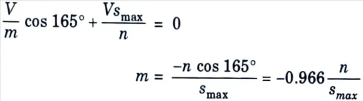
7. Such a choice of m ensures inverter operation at highest firing angle at the lowest motor speed, giving highest power factor and lowest reactive power at the lowest speed. This improves the drive power factor and reduces reactive power at all speeds in the speed range of the drive.
8. The speed-torque curve is shown in Fig. 5.13.1(b).
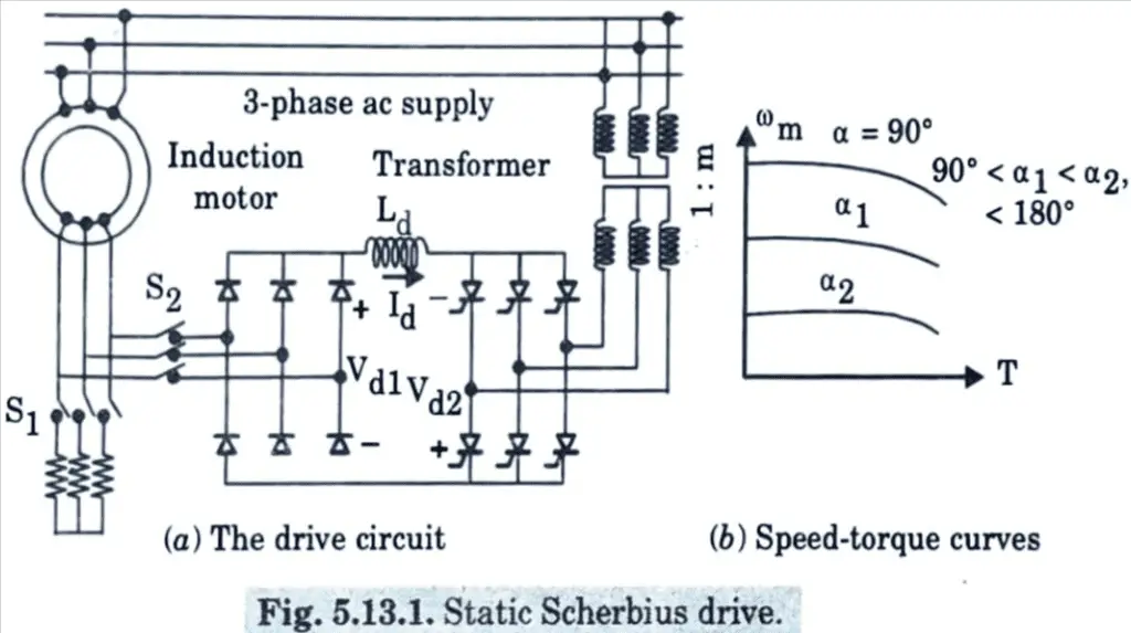
b. Elucidate the operation of brushless DC motor drive in detail.
Ans. 1. A brushless dc motor employing a VSI and trapezoidal PMAC motor is shown in Fig. 5.22.1(a). The stator windings are star connected.
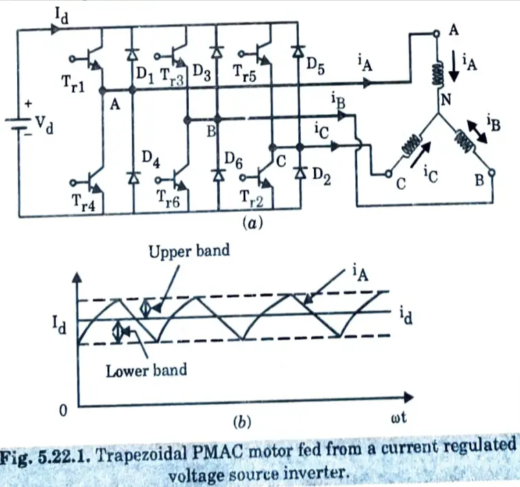
2. The phase voltage waveforms for a trapezoidal PMAC motors are shown in Fig. 5.22.2(a). Let the stator windings be fed with current pulses as shown in Fig. 5.22.2(b). The current pulses are each of 120° duration and are located in the region where induced voltage is constant.
4. The polarity of current pulses is the same as that of induced voltage. Since, the airgap flux is constant, the voltage induced is proportional to speed of rotor.
E = Ke ωm …(5.22.1)
During each 60° interval in Fig. 5.22.2, current enters one phase and comes out of another phase, therefore, power supplied to the motor in each such interval
P = EId + (-E) (-Id) = 2EId = 2Ke ωmId
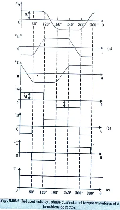
5. Torque developed by motor
The waveform of torque is shown in Fig. 5.22.2(c).
6. According to eq. (5.22.2), torque is proportional to current Id. With current polarity shown in Fig. 5.22.2, the drive gives regenerative braking operation and when current direction is reversed motoring operation is obtained.
2 thoughts on “Electric Drives: AKTU Solved Question Paper”