Quantum Notes can help you to improve your knowledge of Electrical Machines-II. Take advantage of important, often asked questions to ace your Aktu Btech examinations. Join us today and advance! Unit-3 Three Phase Induction Machine-I
Dudes 🤔.. You want more useful details regarding this subject. Please keep in mind this as well.

Important Questions For Electrical Machines-II:
* Aktu Quantum          * B.tech-Syllabus
* Circulars                     * B.tech AKTU RESULT
* Btech 3rd Year          * Aktu Solved Question Paper
Q1. Give the constructional details about three phase induction motor. Which types of rotor are used in 3ɸ induction motor?
Ans. Construction of 3ɸ induction motor: There are two main parts of induction motor:
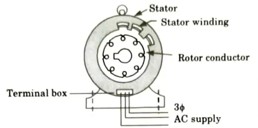
A. Stator:
- 1. It is a stationary part of the motor. This part is made of silicon steel stampings (i.e., thin sheets). The stampings are slotted.
- 2. When complete stator is assembled, the slots are formed on the inner side of the stator.
- 3. The slots may be open type, semi-open type or closed type. In these slots, a 3ɸ winding is accommodated. This winding may be star or delta connected.
- 4. The three ends of this winding are brought out into the terminal box where 3ɸ AC supply can be connected.
- 5. The stator windings, stator and the AC supply connected to the stator winding is shown in Fig.


B. Rotor: There are two types of induction motors depending upon the construction of the rotor:
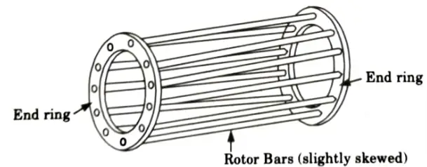
- a. Squirrel cage type rotor:
- 1. This is the most basic and durable construction. The rotor is made up of a cylindrical laminated core and rotor slots that are skewed.
- 2. Rotor conductors, which are thick copper bars, are brazed or welded to end rings in these slots. As a result, the rotor conductors are perpetually short-circuited. As a result, no external resistance can be added to the rotor circuit.
- 3. The rotor body is constructed from silicon steel stampings. The architecture of the rotor resembles a “squirrel cage,” hence the name “squirrel cage type motor.”


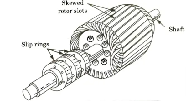
- b. Wound type rotor with slip rings:
- 1. In this type of induction motor, the rotor is wound for the same number of poles as that on the stator.
- 2. The rotor is made up of laminations with slots on the outer periphery in which a 3ɸ rotor winding is placed.
- 3. The three phases are internally highlighted, and the remaining three terminals are brought out and attached to the shaft’s slip rings.
- 4. The slip-rings are composed of copper or phosphor bronze and are supported by three brushes. The brushes are used to make external connections to extra resistances.
- 5. Under normal operating conditions, the slip-rings are short-circuited by a metal collar pushed along the shaft, and the brushes are removed off the slip-rings to prevent frictional losses and wear.
- 6. As a regular 3ɸ winding is used for rotor, this type is called as “phase wound rotor type”. It is also called as “slip-ring type” because slip-rings are used.


Q2. Explain the principle of operation of a 3-phase induction motor.
Ans.
- 1. Let us consider that the rotor is stationary and one conductor is on the rotor as shown in Fig.
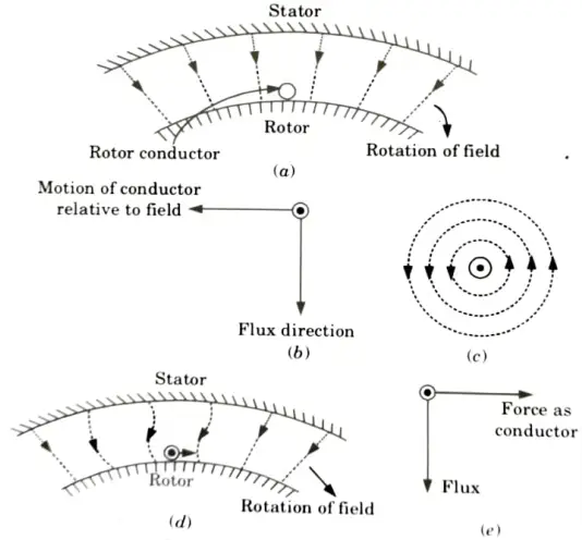


- 2. Let the rotation of the magnetic field be clockwise.
- 3. In a fixed field, a magnetic field travelling clockwise has the same effect as a conductor going anti-clockwise.
- 4. A voltage will be induced in the conductor due to Faraday’s law of electromagnetic induction. A current begins to flow in the rotor conductor as a result of the induced voltage.
- 5. The direction of induced current is downward according to the right-hand rule, as shown in Fig (b).
- 6. The current in the rotor conductor now generates its own magnetic field, as indicated in Fig.(c), resulting in a force on the rotor conductor.
- 7. The direction of force can be calculated using the left-hand rule.
- 8. It can be seen that the force exerted on the conductor is directed in the same direction as the spinning magnetic field.
- 9. Because the rotor conductor is in a slot on the rotor, the force operates in a tangential direction to the rotor, producing torque. The torque produced on all conductors in the same direction is same.
- 10. Since the rotor is free to move, it starts rotating in the same direction. Thus it is noted that a 3ɸ induction motor is a self-starting motor.
Q3. A 3-phase, 4-pole, 60 Hz induction motor has a slip of 5 at no-load, and 7% at full load. Determine the following:
i. The relative speed between stator surface and rotor field.
ii. The relative speed between stator field and rotor field.
iii. The relative speed between stator surface and rotor surface.
Ans. Given: P = 4, f = 60 Hz, slip at no-load = 0.05, slip at full load = 0.07
To Find: i. Relative speed between stator surface and rotor field.
ii. Relative speed between stator field and rotor field.
iii. Relative speed between stator surface and rotor surface.
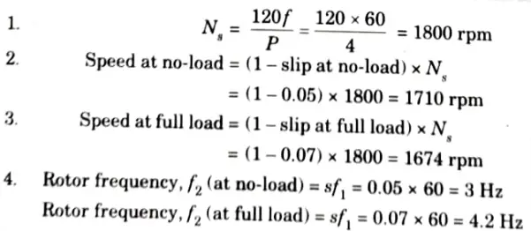


5. Relative speed between stator surface and rotor field
= (Mechanical speed of rotor) + (Speed of rotor field with respect to rotor structure)
Speed of rotor field with respect to rotor structure (at no-load)


Speed of rotor field with respect to rotor structure (at full load)


6. Since both the stator and rotor fields are rotating at synchronous speed of 1800 rpm, speed of rotor field with respect to stator field is zero.
7. Relative speed between stator surface and rotor surface at no-load = 1710 rpm. At full load relative speed is 1674 rpm.
Q4. Explain efficiency characteristic for 3ɸ induction motor ?
Ans.
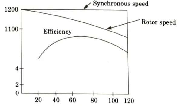
- 1. In 3ɸ IM, there are certain fixed losses (such as core loss, friction and windage loss) in addition to variable losses that include stator and rotor copper losses varying nearly as the square of the load.
- 2. At light loads, the efficiency is quite low because the fixed losses are a relatively large part of the input, with the increase in load.
- 3. The efficiency at first increases rapidly and attains a maximum value. The fixed and variable losses being equal at this point.
- 4. Beyond this point the copper losses (I2R losses) become relatively large, causing the efficiency to decrease.
- 5. The maximum efficiency occurs at about 80 to 95% of rated output. The higher values being applicable to large motors.


Q5. Explain the voltage build-up of an isolated induction generator.
Ans.
- 1. If the bank of delta connected capacitors is operated in parallel with induction generator then the reactive power requirement of induction generator is met by capacitors. This arrangement is shown in Fig.
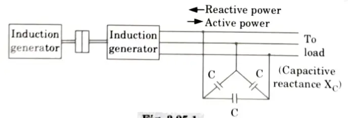


- 2. In this scenario, the induction generator is considered to be an isolated induction generator serving a load. In this instance, an external voltage source is not necessary.
- 3. Unlike synchronous generators, induction generators do not rotate at a constant speed at a constant frequency.
- 4. The speed changes with load because slip is proportional to load. The induction generator has the same frequency as the line to which it is connected.
- 5. In the case of self-excited induction generators, a bank of delta-connected capacitors supplies the magnetising current required to excite the generator.
- 6. The operating frequency of the stator fluctuates as the generator is loaded. It depends on rotor speed and is affected by the load.
- 7. The voltage is primarily decided by the capacitive reactance at that operating frequency.
- 8. The equivalent circuit on per phase basis is as shown in the Fig.
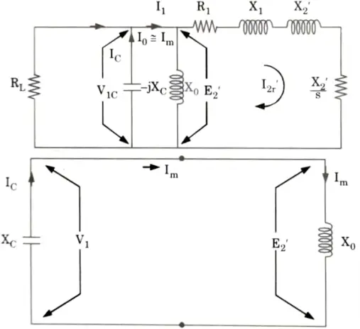


- 9. Initially the induction generator is running at synchronous speed. Im is the magnetizing current in motoring mode.
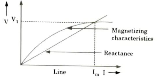
- 10. If voltage drop in R1 and X1 is neglected then V1 ≈ E2. But Im is the magnetising current supplied by capacitors, so it flows through the capacitors.


- 11. The magnetization characteristics is shown in the Fig.


Q6. A squirrel-cage Induction Motor is rated 25 kW, 440 V, 34 50 Hz. On full-load it draws 28.7 kW with line current 50 A and runs at 720 rpm. Calculate:
i. The slip (s)
ii. The power factor, and
iii. The efficiency (𝛈).
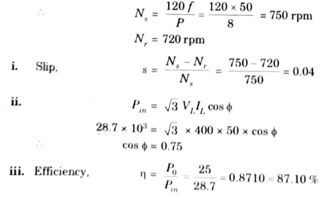
Ans. Given: Pin = 28.7 kW. P = 25 kW, IL = 50 A, f = 50 Hz, Nr = 720 rpm
To Find: i Slip,s.
ii. Power factor, cos ɸ.
ii. Efficiency, 𝛈.
Let us assume P = 8


Important Question with solutions | AKTU Quantums | Syllabus | Short Questions
Electrical Machines-II Btech Quantum PDF, Syllabus, Important Questions
| Label | Link |
|---|---|
| Subject Syllabus | Syllabus |
| Short Questions | Short-question |
| Question paper – 2021-22 | 2021-22 |
Electrical Machines-II Quantum PDF | AKTU Quantum PDF:
| Quantum Series | Links |
| Quantum -2022-23 | 2022-23 |
AKTU Important Links | Btech Syllabus
| Link Name | Links |
|---|---|
| Btech AKTU Circulars | Links |
| Btech AKTU Syllabus | Links |
| Btech AKTU Student Dashboard | Student Dashboard |
| AKTU RESULT (One VIew) | Student Result |
