
Mobile and Wireless Communication: AKTU Solved Question Paper offers comprehensive tools for test preparation. It covers cellular networks, wireless protocols, mobile computing, and network security. For the best exam preparation, these answers to the questions help with conceptual comprehension, problem-solving exercise, and topic selection.
Dudes 🤔.. You want more useful details regarding this subject. Please keep in mind this as well.

Important Questions For Wireless and Mobile Communication:
*Quantum          *B.tech-Syllabus
*Circulars           *B.tech AKTU RESULT
* Btech 4th Year
Section A: Short Question Wireless and Mobile Communication
a. Explain the tradeoffs between the system capacity and co-channel interference.
Ans. In a cellular system of equal cell size, the co-channel interference is a function of a dimensionless parameter known as co-channel reuse ratio Q. This is a ratio of the co-channel distance D and the cell radius R. Now, an increase in Q increases the co-channel distance and thus minimizes the co-channel interference. On the other hand, decrease in Q decreases the cluster size N and hence maximises the system capacity. Thus, the selection of Q is a trade-off between the two parameters, namely, the system capacity and co-channel interferences.
b. Write the name of channel assignment strategies in mobile radio propagation.
Ans. Channel assignment means assigning channels or spectrum bands to radio interfaces for communication.
c. Define the term multiple access.
Ans. Multiple access systems enable multiple users to share the same available channel bandwidth or radio spectrum at the same time.
d. Write down the types of space diversity techniques.
Ans. Space diversity reception or combining methods can be classified into four categories :
- 1. Selection combining
- 2. Feedback or scanning or threshold combining
- 3. Maximum ratio combining
- 4. Equal gain combining
e. Illustrate various persistent methods in CSMA.
Ans. There are several variations of the CSMA strategy.
- i. l-persistent CSMA: The terminal monitors the channel and waits for transmission until it detects that it is idle. The terminal transmits its message with probability one as soon as the channel is idle.
- ii. Non-persistent CSMA :
- 1. With this form of CSMA method, after receiving a negative acknowledgement, the terminal waits a random amount of time before retransmitting the packet.
- 2. This is common in wireless LAN applications where the packet transmission interval is substantially higher than the propagation delay to the farthest user.
- iii. p-persistent CSMA: To slotted channels, P-persistent CSMA is used. When a channel is discovered to be idle, the packet is broadcast with probability p in the first available slot or with probability 1 – p in the following slot.
- iv. CSMA/CD :
- 1. A user analyses its transmission for collisions in CSMA with collision detection (CD).
- 2. If two or more terminals initiate a transmission at the same time, a collision occurs, and the transmission is aborted in midstream.
- 3. This is handled by a user who possesses both a transmitter and a receiver capable of supporting listen-while-talk operation.
- 4. For a single radio channel, this is accomplished by stopping transmission to sense the channel.
- v. CSMA/CA: An attempt is made to increase the performance of CSMA with collision avoidance (CSMA/CA). By default, CSMA/CA employs the carrier sensing technique with exponential back-off.
f. Define the term equalization.
Ans. Equalization is a technique for compensating for intersymbol interference (ISI) caused by multipath in time-division multiplexed channels.
g. Discuss the uplink and downlink frequency band of GSM.
Ans. Uplink frequency band of GSM: For GSM-900, 890-915 MHz is used to transmit formation data from the mobile station to the Base Transceiver Station (BTS). This is known as the uplink frequency band.
Downlink frequency band: For GSM-900 uses 935-960 MHz to send information from Base Transceiver Station (BTS) to mobile station. This frequency band is known as down link frequency band.
h. Define specifications of LEO, MEU and GEO.
Ans. Specification of LEO :
- 1. A low Earth orbit (LEO) is a near-Earth orbit with an orbital period of 128 minutes or less (doing at least 11.25 orbits per day) and an eccentricity of less than 0.25.
- 2. LEO satellites orbit the Earth at altitudes ranging from 160 km to 1,600 km (100 to 1,000 miles).
Specification of MEO :
- 1. MEO is about 20, 200 kilometers above the surface. A satellite at this height takes 12 hours to complete an orbit.
- 2. MEO satellites operate from 10,000 to 20,000 km (6,300 to 12,500 miles) from Earth.
Specification of GEO :
- 1. A geostationary equatorial orbit (GEO) is a circular geosynchronous orbit with a radius of roughly 42,164 km (26,199 miles) in the plane of the Earth’s equator (measured from the centre of the Earth).
- 2. Geostationary satellites orbit at roughly 36,000 km altitude.
i. Discuss the advantages of NGN networks.
Ans. Advantages of NGN:
- 1. Transmission costs are lower.
- 2. Greater power saving.
- 3. Less space requirement and less O and M costs.
j. Compare Wi-Fi and WiMax.
Ans.
| Feature | Wi-Fi | WiMax |
| Standard | 802.11 a/b/g/n | 802.16d/e |
| Data rate (Max) | 300 Mbps | 70 Mbps |
| Operating frequency | 2.4 GHz and 5GHz | 2-11GHz |
| Channel Bandwidth | 20 to 25 MHz | Ranging from 1.25 to 20 MHz |
Section B: Questions Related to Wireless and Mobile Communication
a. Illustrate the MAHO technique and Queuing concept in handoff. Also explain the different types of handoff in mobile communication.
Ans. MAHO :
- 1. In mobile assisted handoff (MAHO), each mobile station measures the received power from nearby base stations and communicates the results of these signal measurements to the serving base station on a continuous basis.
- 2. A handoff occurs when the power received from a neighbouring cell’s base station begins to exceed the power received from the present base station by a specific amount or for a certain period of time.
- 3. The MAHO approach allows the call to be transferred significantly faster than in first-generation analogue systems.
Queuing concept :
- 1. Queuing handoff requests is a means of reducing the likelihood of a call being forced to terminate owing to a lack of accessible channels.
- 2. Handoffs can be queued since there is a finite time interval between when the received signal level goes below the handoff threshold and when the call is terminated owing to inadequate signal level.
- 3. The delay time and queue size are governed by the traffic pattern of the specific service.
- 4. Queuing does not ensure a zero probability of forced termination because long delays allow the received signal level to fall below the minimum tolerable level, resulting in forced termination.
Types of hand off :
- i. Forced handoff :
- 1. When there is a decline in the reported signal level owing to temporary fading rather than the mobile actually moving away from the base station, the handoff of a call is referred to as forced handoff.
- ii. MAHO :
- 1. In mobile assisted handoff (MAHO), each mobile station measures the received power from nearby base stations and communicates the results of these signal measurements to the serving base station on a continuous basis.
- 2. A handoff occurs when the power received from a neighbouring cell’s base station begins to exceed the power received from the present base station by a specific amount or for a certain period of time.
- 3. The MAHO approach allows the call to be transferred significantly faster than in first-generation analogue systems.
- iii. Soft handoff :
- 1. The CDMA system employs soft handoff. All cells in CDMA systems can share the same radio carrier. As a result, the frequency reuse factor K is approaching one.
- 2. Because all cells’ working radio carriers are the identical, there is no need to switch from one frequency to another, only from one code to another. As a result, there is no hard handoff. This is referred to as a soft handoff.
b. Explain p-n sequence generation process with the help of 3 bit linear feedback shift register.
Ans.
- 1. In the case of FH or TH, the PN sequence is used to generate the hopping frequency or the hopping time slots.
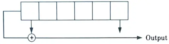
2. A PN code is periodic. A digital shift register circuit with output feedback can generate a sequence with long period and low susceptibility to structural identification by an outsider.
3. The bit rate of a PN code is called the chip rate (1/tchip), the smallest time increment in the sequences of certain period or duration is tchip known as a time chip. The total period consists of NC time chips.
c. Compare the throughput efficiencies and vulnerable time of pure ALOHA and Slotted ALOHA with the help of proper formulation.
Ans. i. Pure ALOHA :
- 1. The pure ALOHA protocol is a data transfer protocol that uses random access. When a message is ready to be transmitted, a user connects to a channel.
- 2. Following a transmission, the user waits for an acknowledgement on the same or a distinct feedback channel.
- 3. In the event of a collision (i.e., when a NACK 0 is received), the terminal pauses for a random amount of time before retransmitting the message.
- 4. When the number of users increases, the likelihood of a collision increases, causing a longer delay.
- 5. For the ALOHA protocol, the vulnerable period is double the packet duration.
- 6. Thus, the probability of no collision during the interval of 2r is found by evaluating Pr (n) given as
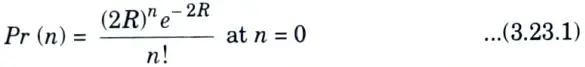
- 7. The probability of no collision is Pr (0) = e-2R, The throughput of the ALOHA protocol is given as
- T = Re-2R …(2)
- 8. The maximum through put achieved by using the ALOHA protocol is given by
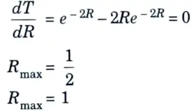
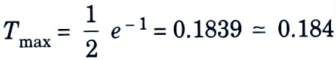
- 9. Substituting Rmax in eg. (2)
ii. Slotted ALOHA :
- 1. In slotted ALOHA, time is divided into equal time slots of length greater than the packet duration τ.
- 2. Each subscriber has synchronised clocks and transmits a message only at the start of a new time slot, resulting in a discrete packet distribution.
- 3. This prevents partial collisions, which occur when a portion of one packet collides with a portion of another.
- 4. As the number of users grows, there will be more delays owing to complete collisions and the ensuing repeated broadcasts of those packets that were originally lost.
- 5. The number of slots a transmitter waits before retransmitting defines the traffic’s delay characteristics.
- 6. While partial collisions are avoided through synchronisation, the susceptible period for slotted ALOHA is only one packet duration.
- 7. The probability that no other packets will be generated during the vulnerable period is e-R, The throughput for the case of slotted ALOHA is thus given by
- T = Re-R …(3)
- 8. The maximum throughput achieved by using the slotted ALOHA protocol is given by
- 9. Substituting Rmax eq. (3)Tmax = e-1 = 0.3679 ≃ 0.368
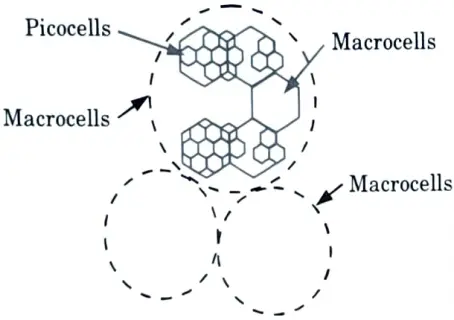
d. Explain the network architecture of UMTS. Also give brief view of IMT2000.
Ans. Network architecture of UMTS :
- 1. The universal mobile telecommunications system (UMTS) is a system capable of offering a wide range of worldwide mobile communication standards with a variety of mobile services.
- 2. One of the architecture ideas being investigated is a mixed cell layout (shown in Fig.) that would consist of macrocells overlaid atop micro and picocells to accommodate a mixed range of traffic.
- 3. This network distributes traffic by having local traffic operate on micro and pico cells and highly mobile traffic operate on macrocells, minimising the amount of handoffs required for fast moving traffic.
- 4. Macrocells will be able to avoid the failures of overlapped cells as well. However, the overlay architecture has a significant disadvantage in terms of spectrum efficiency.
- 5. The UMTS design will offer radio coverage through a network of base stations that are linked to one another and to a fixed network exchange.
IMT2000 :
- 1. IMT-2000 is the global standard for 3G wireless communications, as established by a set of interdependent international telecommunications union (ITU) proposals.
- 2. IMT-2000 establishes a foundation for global access by connecting disparate systems of terrestrial and/or satellite networks.
- 3. In IMT-2000, the year 2000 represents both the year it was introduced and the spectrum used (around 2000 MHz).
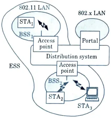
e. Explain Wi-Fi and WiMax Standards.
Ans. Wi-Fi: There are two types of system architectures :
a. Infrastructure based IEEE 802.11: The architecture of infrastructure based IEEE 802.1l network is shown in Fig.
b. Adhoc based IEEE 802.11 :
- 1. The architecture of an adhoc network is shown in Fig.
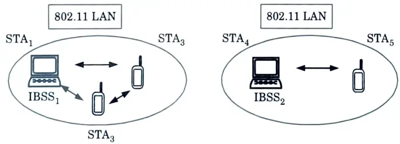
- 2. This type of network provides direct communication within a limited range.
- 3. Here STA1 can communicate with STA2 and STA3 but not with STA4 and STA5 since these are in different IBSS.
WiMax :
- 1. WiMAX is a new broadband wireless data communications technology or mobile internet based on the IEEE 802.16 standard that delivers high-speed data communications (70 Mbps) across a wide region.
- 2. It is a P2MP wireless networking technique.
- 3. WiMAX is a WMAN standard created by IEEE 802 working group number 16, which specialises in broadband wireless access. It is appropriate for rural applications.
Section 3: Overview of Wireless and Mobile Communication
a. If a signal to interference ration of 15 dB is required for satisfactory forward channel performance of a cellular system, calculate the frequency reuse factor and cluster size that should be used for maximum capacity if the path loss exponent is (a) n = 4, (b) n = 3 ? Assume that there are 6 co-channel cells in first tier, and all of them are at the same distance from the mobile. Use suitable approximations.
Ans. a. For the case with n = 4 :
1. First, let us consider a 7 cell reuse pattern.
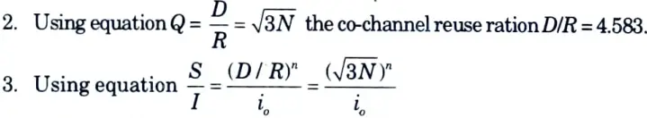
where i0 is the number of co-channel interfering cells.
4. Hence, the signal to noise interference ratio is given by
S/I = [(4.5834)] / 6 = 75.3 = 18.06 dB
5. Since, this is greater than the minimum required S/I, N = 7 can be used.
b. For the case with n = 3 :
2. Hence, signal to noise interference ratio is given by,
S/l = [(4.583)3] / 6 = 16.04 = 12.05 dB
3. Since this is less than minimum required S/I, we need to use a larger N.
4. Using N = i2 + ij + j2, the next possible of N is 12, (i = j = 2).
5. The corresponding co-channel ratio is given by Q = D/R
6. Then the signal to interference ratio is given by
S/F= 1/6 x 62 = 36 = 15.56 dB
7. Since this is greater than the minimum required S/I, N = 12 can be used.
b. Explain frequency reuse concept with the help of proper cellular diagram. Also draw a cellular system with 19-cell reuse and locate the co-channel cells for this system.
Ans.
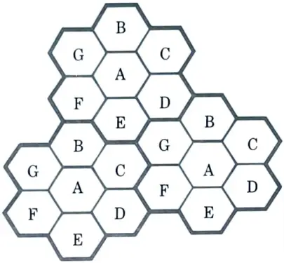
- 1. Frequency reuse or frequency planning refers to the process of identifying and allocating channel groups for all cellular base stations in a system.
- 2. Fig. depicts the notion of cellular frequency reuse. The same set of frequencies is used by cells with the same letter. A cell cluster is shown in bold and repeated across the service region.
- 3. In this example, the cluster size N is seven, and the frequency reuse ratio is one-seventh, because each cell comprises one-seventh of the total number of accessible channels.
- 4. To understand the frequency reuse concept, consider system which has a total of S duplex channels available for use.
- 5. If each cell is allocated a group of K channels (such that K < S), and if the S channels are divided among N cells into unique and disjoint channel groups which each have the same number of channels, the total number of available radio channels can be represented as
S = KN
- 6. The N cells which collectively use the complete set of available frequencies is called as a cluster. Ifcluster is replicated M times within the system, the total number of duplex channels, C can be used as a measure of capacity and is given by
C = M K N = MS
- 7. So the capacity of a cellular system is directly proportional to the number of times a cluster is replicated in a fixed service area. The factor N is called the cluster size and is typically equal to 4, 7 or 12.
- 8. The frequency reuse factor of a cellular system is given 1/N, since each cell within cluster is only assigned 1/N of the total available channels in the system.
∴ 1/N = K/S
Section 4: Btech Solved Questions of Wireless and Mobile Communication
a. Classify and explain different types of vocoders. Also give properties of speech signal.
Ans. Types of vocoders :
- i. Channel vocoder :
- 1. The first system to analyse speech was the channel vocoder.
- 2. Channel vocoders are frequency domain vocoders that determine the envelope of the speech signal for a number of frequency bands before sampling, encoding, and multiplexing the encoded outputs of the other filters.
- 3. Samples are taken every 10 to 30 milliseconds.
- 4. In addition to the energy information for each band, the voiced/unvoiced decision and the pitch frequency for voiced speech are sent.
- ii. Formant vocoder :
- 1. The formant vocoder employs fewer control signals than the channel vocoder, allowing it to operate at lower bit rates.
- 2. The formant vocoder seeks to convey the positions of the peaks (or formants) of the spectral envelope rather than sending samples of the power spectrum envelope.
- 3. The formant vocoder must be able to recognise at least three formants in order to represent speech sounds, and it must also be able to regulate the formant intensities.
- 4. Speech can be reproduced using formant vocoders at bit rates lower than 1200 bits/s.
- 5. Since it is difficult for formant vocoders to determine the precise location of formants and formant transitions in human speech, they have not proven very successful.
- iii. Cepstrum vocoder :
- 1. The Cepstrum vocoder uses inverse Fourier transformation to separate the excitation and voice tract spectrums. This separation produces the cepstrum signal.
- 2. The cepstrum’s low frequency coefficients correspond to the spectral envelope of the vocal tract, while the high frequency excitation coefficients create a periodic pulse train at multiples of the sampling time.
- 3. Linear filtering is used to separate the cepstral coefficients of the vocal tract from the excitation coefficients.
- 4. The vocal tract cepstral coefficients are Fourier converted in the receiver to produce the vocal tract impulse response. The original voice is reconstructed by convolving this impulse response with a synthetic excitation signal.
- iv. Voice excited vocoder :
- 1. Voice-excited vocoders do away with the necessity for pitch extraction and voicing detection.
- 2. This method employs a blend of PCM transmission for the low frequency band of speech and channel vocoding for higher frequency bands.
- 3. The synthesiser generates a pitch signal by rectifying, bandpass filtering, and clipping the baseband signal.
- 4. Voice excited vocoders have been constructed to operate at bit rates ranging from 7200 to 9600 bits per second, and their quality is often superior to that obtained by pitch excited vocoders.
Properties of speech signal :
- 1. Short time zero crossing
- 2. Short time energy
- 3. Auto correlation
b. Illustrate the different types of frequency hopped multiple Access with the help of proper hop timing diagram.
Ans. 1. The transmitter in frequency hopping systems changes the carrier frequency according to a specific hopping pattern, which means that the frequency is constant in each time chip but varies from chip to chip.
2. There are two types of frequency hopping :
- i. Slow frequency hopping (SFH) :
- 1. In SFH, one or more data bits are transferred in a single hop: the hoping rate is lower than the message bit rate.
- 2. One advantage is the ability to recognise coherent data.
- 3. Slow hopping systems frequently use (burst) error-control coding to repair loss of (many) bits in one hope.
- 4. SFH is a prominent wireless local area network method (LANs).
- ii. Fast frequency hopping (FFH) :
- 1. The FH rate is higher than the message bit rate because one data bit is split over numerous hops in FFH.
- 2. Coherent signal detection is challenging in fast hopping and is rarely used.
- 3. FFH is adopted in bluetooth.
FHSS generator :
1. Consider a fast hop system in which there are k frequency hops in every message bit duration tm. Thus, the chip duration is
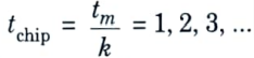
2. The number of frequencies is in a power of two because it is generated by a PN sequence generator control, and PN sequences are related to powers of two. The ML sequence that is, c chips, will produce M = 2c frequencies for each distinct combination of these digits.
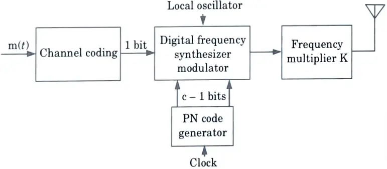
3. As shown in Fig., one bit comes from the message and c-1 bit come from the PN code generator. The c – 1 bit from the PN code generator then hop this FSK signal over the range of possible frequencies.
4. There is a frequency multiplier K at the output of the system. It is to increase the bandwidth and thereby increase the processing gain.
5. Considering again the fast hopping case, if M frequencies are separated by f1 = 1/tchip = k/tm, then the signal bandwidth is given by
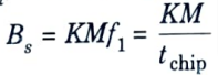
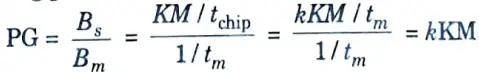
6. Hence, the processing gain is calculated as
Section 5: Sem 7 Questions of Wireless and Mobile Communication
a. Illustrate various Equalization techniques with the help of proper block diagram.
Ans.
- 1. The two broad categories of equalisation techniques are linear equalisation and non-linear equalisation.
- 2. These classifications are based on how an adaptive equalizer’s output is applied to its subsequent control (feedback).
- 3. Typically, the decision-making component in the receiver processes the analogue signal d(t).
- 4. To determine the value of d, the decision-maker applies a thresholding operation to the digital data bit that is being received (t).
- 5. The equalisation is linear if d(t) is not employed in the feedback path to adapt the equaliser. The equalisation is non-linear, however, if d(t) is feedback to alter the equalizer’s future outputs.
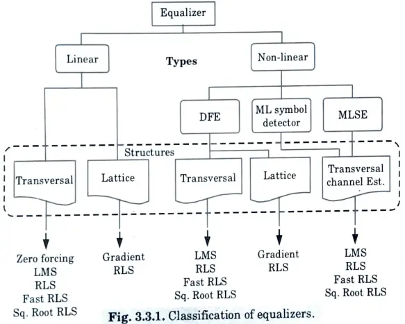
- 6. In order to build linear and non-linear equalisers, numerous filter architectures are required. Also, there are different algorithms utilised to customise the equalisation for each structure.
b. Explain FDMA and TDMA in detail with suitable diagram.
Ans. FDMA :
- 1. Frequency division multiple access deals with radio frequency (RF) carriers.
- 2. It is a technique whereby the spectrum is equally divided into frequencies and then assigned to different users, as shown in Fig.
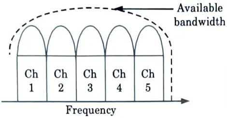
- 3. As a result, the available bandwidth is split up into several channels with narrower band widths.
- 4. With FDMA, a channel can only have one subscriber assigned to it at any given moment. As a result, the channel is now off-limits to other conversations.
- 5. FDMA transmission needs two one-way channels-one for transmitting and the other for receiving-in order to prevent interference.
- 6. From first-generation analogue systems, full-duplex or frequency division duplex (FDMA) has been used.
- 7. A distinct frequency band is allotted to each user for use in both transmission and reception. The same frequency band may not be used by anyone else.
- 8. As each channel only needs to support a single user and the accompanying baseband, most FDMA systems typically use modest channel bandwidth.
TDMA :
- 1. Time division multiple access improves spectrum capacity by splitting the spectrum’s use into time slots.
- 2. It gives each user brief access to the entire RF channel. At certain times, other users share the same frequency channel.
- 3. As a result, TDMA assigns each user (or channel) a time slot in which they can transmit or receive, dividing the available spectrum into several time slots as depicted in Fig.
- 4. The Fig. illustrates how time slots are distributed to users in a round-robin fashion, creating time frames, with one time slot assigned to each user each frame.
- 5. The base station swaps users on the channel continuously. Similar to TDM, TDMA can be either asynchronous or synchronous. It rules the second-generation mobile cellular network as the predominant technology.
- 6. Time division multiple access systems transmit data in a buffer and hence this is a bursty communication method. Thus, the transmission of each channel is not-continuous.
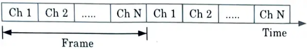
- 7. During the channel’s allotted time slot, the input data to be transferred is burst delivered at a greater rate after being buffered over the preceding frame.
- 8. TDMA is used to transport digital data because analogue signals cannot be sent directly over it due to buffering requirements.
Section 6: Answer with Diagram of Wireless and Mobile Communication
a. Explain GSM with the help of proper network architecture block diagram. Also give brief view of various interface standards in GSM.
Ans. 1. Fig. shows the block diagram of the GSM system architecture. The mobile stations (MSs) communicate with the base station subsystem (BSS) over the radio air interface.
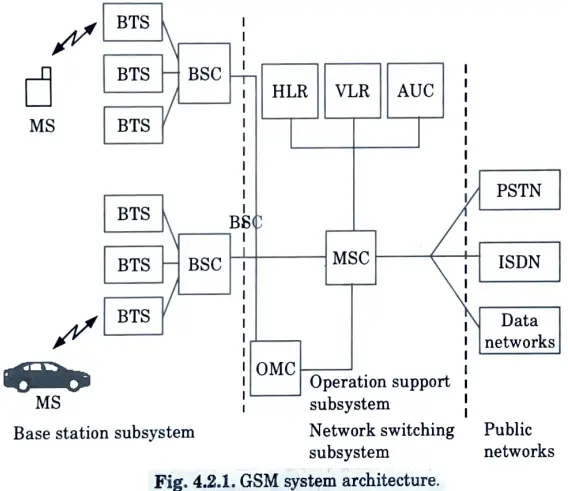
2. The GSM system architecture consists of three major interconnected subsystems :
a. Base station subsystem (BSS) :
- 1. The BSS, also referred to as the radio subsystem, establishes and controls radio transmission routes between mobile stations and the mobile switching centre (MSC).
- 2. The BSS is also responsible for overseeing the radio interface that connects mobile stations to all other GSM subsystems.
- 3. Through the MSCs, each BSS connects the MS to the NSS. Each BSS is made up of numerous base station controllers (BSCs).
- 4. Each BSC in the BSS normally controls up to several hundred base transceiver stations, and all of the BSCs are connected to a single MSC (BTSs).
- 5. The BSC, not the MSC, handles mobile handoffs between two BTSs under the same BSC’s command. This significantly lessens the MSC’s switching workload.
b. Network and switching subsystem (NSS) :
- 1. The NSS oversees the system’s switching capabilities and enables MSCs to communicate with other networks such as the PSTN and ISDN.
- 2. The NSS is in charge of switching GSM calls between external networks and the radio subsystem’s BSCs, as well as administering and providing external access to many client databases.
- 3. In the NSS, there are three different databases :
- i. HLR (Home Location Register) :
- 1. The HLR is a database which contains subscriber information and location information for each user who resides in the same city as the MSC.
- ii. VLR (Visitor Location Register) :
- 1. The VLR is a database that briefly holds the IMSI and customer information for each roaming subscriber who visits a specific MSC’s coverage region.
- 2. After a roaming mobile is registered in the VLR, the MSC provides the relevant information to the visiting subscriber’s HLR, allowing calls to the roaming mobile to be routed appropriately via the PSTN by the roaming user’s HLR.
- iii. AUC :
- 1. The authentication centre (AUC) is a secure database that manages the authentication and encryption keys for each and every subscriber in the HLR and VLR.
c. Operation support subsystem (OSS) :
- 1. The OSS facilitates GSM operation and maintenance, allowing system engineers to monitor, diagnose, and troubleshoot all parts of the GSM system.
- 2. The OSS provides support for one or more Operation Maintenance Centers (OMC), which are used to monitor and maintain the performance of each MS, BS, BSC, and MSC in a GSM system.
- 3. The OSS has three main functions, which are :
- i. To maintain all telecommunications hardware and network operations with a particular market.
- ii. Manage all charging and billing procedures, and
- iii. Manage all mobile equipment in the system.
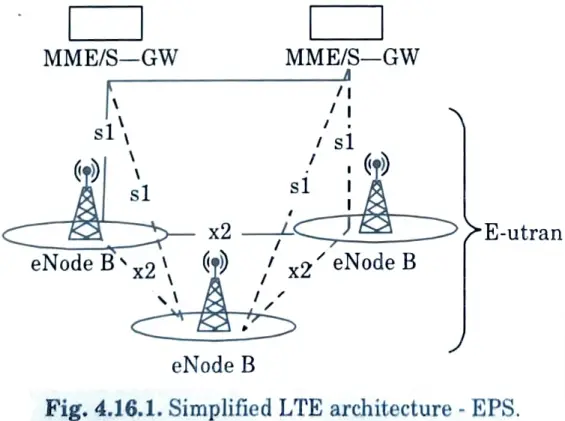
b. Explain long term evolution (LTE) architecture in detail with diagram. Also give brief view of mobile satellite communication.
Ans. Long term evolution :
- 1. Long-term evolution to an all-IP flat architecture system from the existing UMTS circuit and packet switching hybrid network. The simplicity of the LTE architecture is depicted in Fig.
- 2. The network side of the evolved UMTS terrestrial radio access network (E-UTRAN) is made up of just evolved Node Bs (eNode Bs or eNBs), resulting in a reduced design.
- 3. LTE enables cell sizes ranging from tens of metres to 100 kilometres.
- 4. The E-UTRAN and the evolved packet core are new blocks particular to evolved UMTS evolution, LTE, also known as the evolved packet system (EPS) (EPC). The EPS is entirely based on intellectual property.
- 5. The LTE access network E-UTRAN is simply a network of BSs and eNBs, generating a flat architecture. There is no centralized intelligent controller and the eNBs are normally interconnected by the X2 interface and towards the CN by the S1 interface.
Mobile satellite communication :
- 1. In mobile satellite communication, the satellite and mobile systems are combined.
- 2. Frequency reuse can be accomplished using antenna spot beams. The areas of beam projection are represented as cells.
- 3. Miniature satellite earth stations are used to send and receive satellite communications. These signals can then be forwarded to the MSC, which will handle the rest of the signal routing.
- 4. The system provides communication services to mobile users within a specified service region. Users communicate with other mobile devices or fixed users via one of the visible satellites.
- 5. Fixed network users are accessed by big permanent stations known as gateways, which transport a vast amount of traffic, whereas mobiles are small portable equipment that can only support a few channels.
- 6. There could be one or more space segments, each consisting of a single satellite or a group of interconnected satellites. The space segments can be used depending on the service area and application.
- 7. Telemetry and control ground stations, which are needed to monitor and control satellites, are included in the space segment.
Section 7: Aktu University Questions of Wireless and Mobile Communication
a. Write short note on: (i) Mobile Adhoc Network (MANET) (ii) Bluetooth
Ans. i. Mobile adhoc network :
- 1. MANETs are groupings of mobile nodes that dynamically construct short-lived networks in the absence of fixed infrastructure.
- 2. Each mobile node has a wireless transmitter as well as a receiver with an appropriate antenna.
- 3. These mobile nodes are linked by wireless links and serve as routers for the rest of the network’s mobile nodes.
- 4. Mobile adhoc network nodes are free to move and organise themselves in any way they see fit.
- 5. These characteristics make MANETs particularly practical and easy to deploy in regions where existing infrastructure is insufficient to support communication, such as disaster zones or difficult-to-deploy sites.
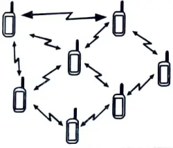
- 6. MANETs are short-term, spontaneously wireless networks of mobile nodes talking with one another that do not require any fixed infrastructure or central control.
- 7. It is a self-contained network of mobile nodes, mobile terminals, or mobile stations that act as routers and are linked together via wireless networks.
- 8. Wireless connectivity exists among participating mobile nodes at any given time, depending on their locations, antenna coverage pattern, transmit power levels, and co-channel interference levels, either in the form of random multihop broadcasts or an adhoc network.
- 9. Network communication and management functions are frequently distributed.
- 10. MANET topology may change from time to time when nodes move or adjust their transmission and reception characteristics.
ii. Bluetooth :
- 1. Bluetooth is an open wireless technology standard for transmitting data over short distances between fixed and mobile devices, resulting in highly secure personal area networks (PANs).
- 2. Bluetooth is a low-cost radio-based wireless technology on a single chip. Bluetooth technology is aimed at adhoc piconets with very low coverage (up to 100 m) and no infrastructure required.
b. Write short note on (i) Light fidelity (ii) Introduction to 4G and 5G.
Ans. i. Light fidelity :
- 1. Light Fidelity (Li-Fi) is a wireless communication system that is bidirectional, high-speed, and completely networked, similar to Wi-Fi.
- 2. Li-Fi is a type of visible light communication and a subset of optical wireless communications (OWC), and it could be used to supplement or even replace RF communication (Wi-Fi or cellular networks) in data broadcasting scenarios.
- 3. It is wire and UV visible-light communication, or infrared and near ultraviolet communication, rather than radio-frequency spectrum, that carries significantly more information and has been offered as a remedy to RF-bandwidth limits.
- 4. Both Wi-Fi and Li-Fi use the electromagnetic spectrum to transport data, however Wi-Fi uses radio waves and Li-Fi uses visible light.
- 5. Li-Fi is predicted to be ten times less expensive than Wi-Fi. The potential drawbacks include limited range, inadequate dependability, and hefty installation costs.
- 6. Li-Fi, like Wi-Fi, is wireless and use similar 802.11 protocols; however, it employs visible light communication (instead of radio frequency waves).
- 7. Standard defines three PHY layers with different rates :
- i. The PHY I was established for outdoor application and works from 11.67 kbit/s to 267.6 kbit/s.
- ii. The PHY II layer permits reaching data rates from 1.25 Mbit/s to 96 Mbit/s.
- iii. The PHY III is used for many emissions sources with a particular modulation method called colour shift keying (CSK). PHY III can deliver rates from 12 Mbit/s to 96 Mbit/s.
- 8. On-off keying (OOK) and variable pulse position modulation are the modulation formats supported by PHY I and PHY II (VPPM).
- 9. The clock is included in the transmitted data using Manchester coding for the PHY I and PHY II layers by encoding a logic O with an OOK symbol “001” and a logic 1 with an OOK symbol “10,” all with a DC component. In the event of an extended run of logic 0’s, the DC component prevents light extinction.
ii. Introduction to 4G :
- 1. 4G stands for the fourth generation of cellular wireless standards. It is a successor to 3G and 2G families of standards.
- 2. The max download speed for 4G service is set at 100 Mbit/s for high mobility devices (such as telephones) and 1 Gbit/s for low mobility devices (such as stand-alone wireless modems).
- 3. A 4G system is planned to deliver a comprehensive and secure all IP-based solution to users, including ultra-broadband internet access, IP telephony, gaming applications, and streamed multimedia.
- 4. The wireless telecommunications industry has largely used the term 4G as a shorthand way to designate sophisticated wireless technologies that, among other things, are based on or employ wide channel OFDM technology and all IP-based architecture.
- 5. In 4G, the user has the freedom and flexibility to choose any desired service with reasonable QOS and an affordable price, at any time and from any location.
Introduction to 5G :
- 1. Fifth-generation wireless (5G) is the most recent iteration of cellular technology designed to improve wireless network speed and responsiveness.
- 2. With 5G, data carried through wireless broadband connections can move at multigigabit speeds, with some estimates claiming peak speeds of up to 20 gigabits per second (Gbps).
- 3. Because of higher accessible bandwidth and superior antenna technology, 5G will enhance the amount of data transmitted across wireless systems.
2 thoughts on “Wireless and Mobile Communication: AKTU Solved Question Paper”