
AKTU question paper with answers supplies B.Tech students with significant practise material for Advanced Concrete Design exams by providing a comprehensive set of exam-oriented questions and in-depth explanations.
Dudes 🤔.. You want more useful details regarding this subject. Please keep in mind this as well.

Important Questions For Wireless and Advanced Concrete Design:
*Quantum          *B.tech-Syllabus
*Circulars           *B.tech AKTU RESULT
* Btech 4th Year
Section A: Short Question Advanced Concrete Design
a. Define liquid retaining structures.
Ans. Liquid Retaining Structures: It is a structure designed to hold a liquid (usually water) and be used for a variety of purposes later on. Dam, high-level water tank, underground tank, surface reservoir, and so on.
b. What is approximate method for design of tank ?
Ans. “Approximate Method of Analysis” for water tanks :
- 1. In this method it is assumed that in case of circular tanks, bottom 1/3rd or 1 m (whichever is greater) and for rectangular tanks, bottom 1/4th or 1 m(whichever is greater) is predominantly under cantilever action.
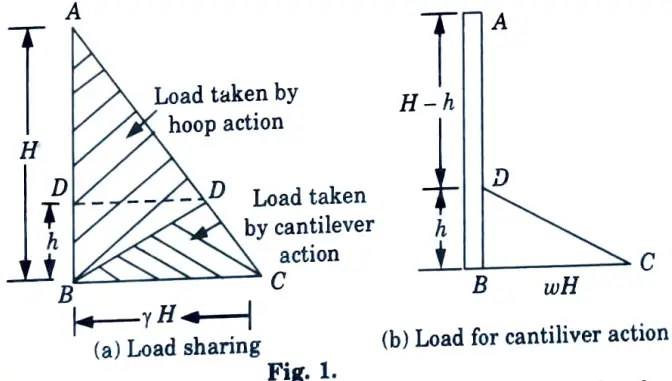
- 2. Rest of the wall is resisting the water pressure by forces developed in horizontal direction.
- 3. In this method, the bottom height of wall BD is designed as cantilever fixed at B and subjected to triangular load given by area DBC of pressure triangle.
- 4. Load at B = wH, reinforcement for cantilever action is provided up to height ‘h’ from inner face of wall.
c. Define intze tanks.
Ans. In the case of large diameter tanks, a cost-effective alternative would be to reduce the diameter at the bottom with a conical dome. This type of tank is known as an Intze tank and is widely used.
d. Define top dome for overhead tanks.
Ans. It is the intze water tank’s top cover. Its members are typically domical in shape. A dome is a type of shall formed by rotating a regular axis. A parabola, circular, or elliptical curve about one of its axis.
e. What is prestressing ?
Ans.
- 1. Prestressing is defined as applying a predetermined force or moment to a structural member in such a way that the combined internal stresses in the member caused by this force or moment and any anticipated condition of external loading are confined within specific limits.
- 2. In general, prestressing entails the imposition of stresses in the opposite sign to those caused by the subsequent application of working roads.
f. Define degree of prestressing.
Ans. The magnitude of the prestressing force in relation to the resultant stress in the structural member of working load.
g. What are ultimate tensile strength ?
Ans. It is the maximum stress that a material can withstand while being stretched or pulled.
h. Define kern distance.
Ans. It is the distance in which compressive point load is applied without producing any tensile stress in the cross-section.
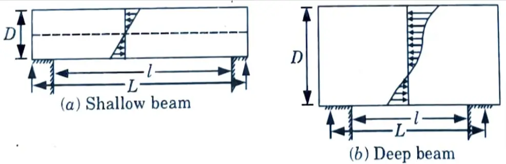
i. Define deep beams.
Ans. As when per IS 456: 2000, a beam shall be deemed to be a deep beam LID the ratio of the effective span (l) to the overall depth (D), i.e., ratio is less than
- i. 2.0 for simply supported beams.
- ii. 2.5 for a continuous beam.
j. Where corbel are used ?Ans. A corbel or a nib is a short cantilever deep beam. Corbels are used to support heavy loads, such as crane or gantry loads, in industrial buildings. Corbels use strut-tie action to transfer loads to the supports.
Section B: Long Question of Advanced Concrete Design
a. Find out the earth pressure on tank when wall with moist back fill when the tank is empty and underground.
Ans. Tank is Empty and Active Earth Pressure is Present :
1. Active earth pressure on wall for dry and cohesion less soil.
2. Active earth pressure on wall for the submerged saturated soil.
i. In the case (1), the active earth pressure due to soil acts on the tank walls with maximum value at the base equal to kaγsH.
where, ka = Coefficient of active earth pressure.
γs = Density of soil.
H = Height or depth of water.
ii. The coefficient of active earth pressure can be obtained by,

where, ɸ = Angle of repose or angle of internal friction of soil.
iii. If there are chances of rise of water table then the active earth pressure due to submerged saturated soil is to be taken into account as shown in Fig. 1.13.1(b).

iv. The active earth pressure at the base of the wall, in the case of submerged soil is given as,
Pa = KaγssH + γwH
where, γss = Density of the saturated soil.
γw = Density of water.
Pa = Active earth pressure.
H = Height of tank.
Tank is Full and there is no Earthfill: Tables for moments, shear, and direct tension developed in rectangular tank walls for various types of joints and load conditions are provided in IS code 3370 (Part-IV). These values can be directly used to design the water tanks.
b. Analyze the overhead tanks for wind forces.
Ans.
- i. Wind load must be calculated in accordance with IS 875. (Part 3). Load combinations must account for both tank empty and tank full conditions. While calculating the force action and stresses, the worst combination of the load due to the aforementioned factors must be considered.
- ii. Wind and seismic loads shall not be assumed to act together.
c. Write the advantages of prestressed concrete over reinforced concrete.
Ans. Advantages of Prestressed Concrete :
- 1. Because high strength concrete and steel are used in PSC, it is thinner and lighter than RCC sections.
- 2. In PSC, the entire concrete area is effective in resisting loads, whereas in RCC, concrete below the neutral axis is ignored.
- 3. Thinner PSC sections result in less self weight and thus overall economy.
- 4. Because of its lighter weight and thinner section, PSC is used for long span bridges and flyovers. As a result, PSC is used in heavily loaded structures.
- 5. Prestressed concrete members show less deflection.
- 6. Since PSC concrete does not crack, rusting of steel is minimised.
- 7. Prestressed concrete is used in structures that develop tension or are subjected to vibrations, impact, and shock, such as girders, bridges, railway sleepers, electric poles, gravity dams, and so on.
- 8. Precast members such as electric poles and railway sleepers can be easily manufactured in factories using simple prestressing methods.
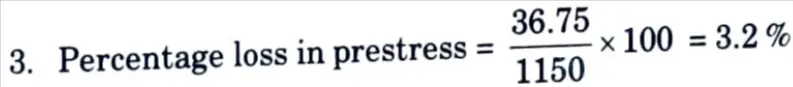
d. In a post tensioned beam the cable is subjected to 1150 N/mm2. If the slip at the jacking end is found to be 3.50 mm. Find the percentage loss of stress due to this case if the beam is 20 m long.
Ans. Given : Stress = 1150 N/mm2, Slip at jacking = 3.5 mm, Length of beam = 20 m
To Find: Percentage loss of stress due to anchorage slip. Assume modulus of elasticity, E = 2.1 x 10⁵ N/mm2
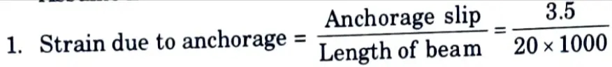
= 1.75 x 10⁻⁴
2. Loss of stress = Strain x modulus of elasticity
= 1.75 x 10-4 x 2,1 x 105 = 36.75 MPa
e. What situation when deep beams are used? And write empirical expressions for lever arm (z).
Ans. Situation for Deep Beam: Deep beams are encountered in the following situations.
- i. Foundation Beams: They transferring concentrated column loads to the supporting soil.
- ii. Transfer Girders or Wall Beams :
- a. The transfer girders or wall beams at a building’s intermediate floor level where some columns must be stopped.
- b. A beam of the same depth as a storey height transfers the load of the stopped columns to the adjacent columns.
- iii. Bunker Walls or Tank Walls: Bunker or tank walls function as deep beams supported by columns at corners or intermediate points.
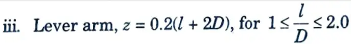
Expression for Lever Arm: The lever arm z of the deep beam shall be determined as follows :
i. For simply supported beams,
Z = 0.2(l + 2D), for 1 ≤ l/D ≤ 2.0
= 0.61, for l/D < 1.0.
ii. For continuous beams,
z = 0.2(l + 1.5 D), for 1 ≤ l/D ≤ 2.5
= 0.51, for l/D < 1.0.
Section 3: Repeated Questions of Advanced Concrete Design
a. A clarifier tank of diameter 35 m has walls 5.25 m tall above its base slab. Using M25 concrete and Fe 415 steel design the tank.
Ans. Given: Diameter of tank, D = 35 m, Depth of tank, d = 5.25 m, M25 and Fe415
To Find: Design of tank.
1. Maximum Hoop Tension (T):
= 900.375 kN per m height of the wall
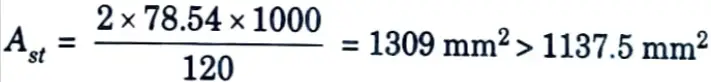
2. Area of Steel, Ast :
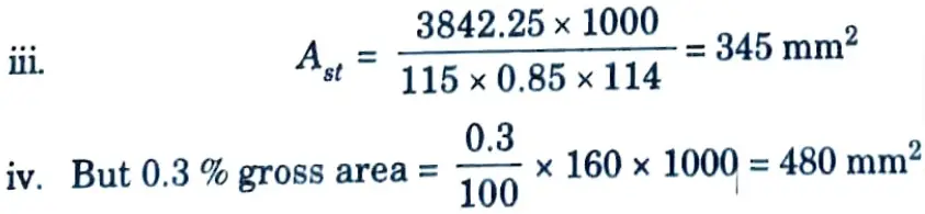
i. Area of steel is given by,
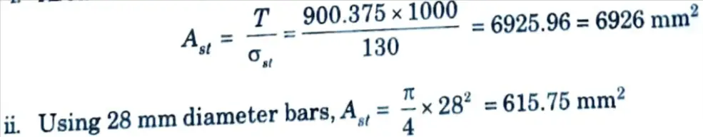
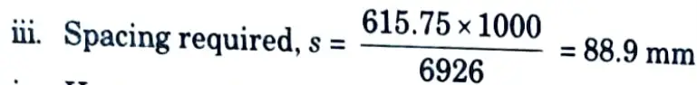
iv. Hence, provide 28 mm diameter bars @85 mm c/c
v. At a distance 2.625 m from top, T = 450.188 kN per m and Ast, req 3463 mm², hence spacing can be doubled.
3. Thickness of Tank Wall :
i. The thickness of the wall should be such that the tensile stress in concrete should not exceed the permissible value, σct.
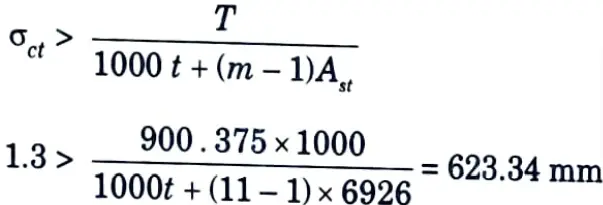
Hence, providing a thickness of 650 mm for tank wall.
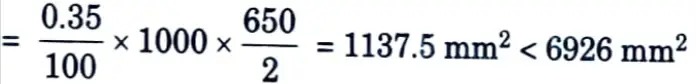
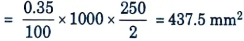
ii. Ast, min = 0.35 % of cross-section area
The spacing of hoops ≯ 300 mm or the thickness of section.
Hence, providing 28 mm diameter hoops @88 mm c/c along the wall the spacing is increased to 196 mm c/c at a distance 2.225 m from top.
4. Distribution Reinforcement :
i. Distribution reinforcement is provided @ 0.35 % = 1137.5 mm2
ii. Providing 8 mm diameter bars @ 120 mm cdc as vertical steel.
5. Design of Base/Floor Slab :
i. Since the tank floor is resting on the ground the load gets directly transferred to the soil. Hence, providing a minimum thickness of 250 mm and 0.35 % minimum steel in each direction.
ii. Hence, provide 8 mm diameter bar @110 mm c/c in both direction at top and bottom face of the floor slab.
b. Find the active earth pressure for the tank if back fill is saturated sandy soil.
Ans. 1. Active earth pressure on wall for dry and cohesion less soil.
2. Active earth pressure on wall for the submerged saturated soil.
i. In the case (1), the active earth pressure due to soil acts on the tank walls with maximum value at the base equal to kaγsH.
where, ka = Coefficient of active earth pressure.
γs = Density of soil.
H = Height or depth of water.
ii. The coefficient of active earth pressure can be obtained by,
where, ɸ = Angle of repose or angle of internal friction of soil.
iii. If there are chances of rise of water table then the active earth pressure due to submerged saturated soil is to be taken into account as shown in Fig. 1.13.1(b).
iv. The active earth pressure at the base of the wall, in the case of submerged soil is given as,
Pa = KaγssH + γwH
where, γss = Density of the saturated soil.
γw = Density of water.
Pa = Active earth pressure.
H = Height of tank.
Section 4: Btech AKTU Questions of Advanced Concrete Design
a. Find the bending moment for the base slab of tank situated above ground level.
Ans. Bending Moment for The Base Slab :
1. The bending moments are to be computed at the end and at mid span.
2. At ends the bending moment will be a hogging moment caused by water pressure on the
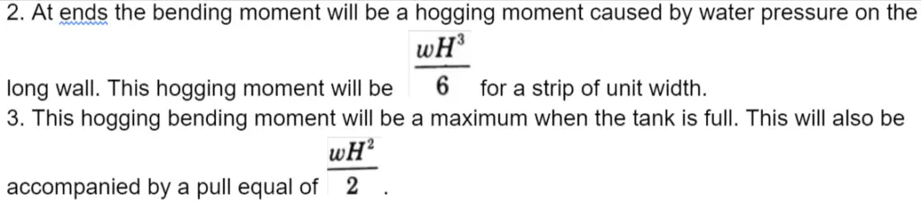
4. The bending moment at mid span will consist of the sagging moment due to weight of water and weight of base slab and a hogging moment due to water pressure on the side walls.
5. The net sagging bending moment per metre width when the depth of water is h is given by
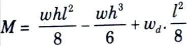
where wd = Weight of the slab per metre2
For M to be a maximum,
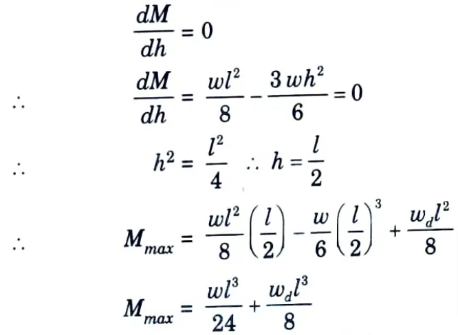
6. The pull corresponding to this condition
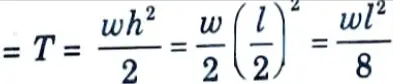
is full, there may be a hogging bending moment at mid span. In such a case, the mid span section should also be designed for this hogging bending moment accompanied by the pull corresponding to the full tank condition.
b. A reinforced concrete water tank is 6 m x 3 m with a maximum depth of 2.5 m, 150 mm x 150 mm splays are provided at the junction of walls and base slab. The tank is supported on brick masonry walls all round. Design the tank use M20 concrete and mild steel reinforcement.
Ans. Given: Size of tank = 6 x 3 m, Depth of tank = 2.5 m, Size of splays = 150 x 150 mm, M20 concrete.
To Find: Design the tank.
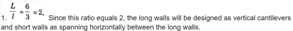
2. Design of Long Wall :
i. These are designed as vertical cantilevers. Since splays are provided it is enough if the cantilevering effect is considered above the top of the splay, i.e., the effective height of the cantilevering long wall will be
2.50 – 0.15 = 2.35 metre
ii. Maximum bending moment per metre width of the long wall
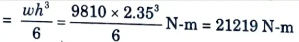
This bending moment produces tension near the water face.
iii. Adopting c =7 N/mm², t = 100 N/mm² and m= 13.33 and equating the moment of resistance to the bending moment, we have
1.333 bd2 = 1.333 x 1000d2 = 21219 x 1000
∴ d = 127mm
iv. With a clear cover of 25 mm and providing 16 mm ¢ bars the overall depth required
= 127 + 8 + 25 = 160 mm
Provide a thickness of 160 mm
v. Actual effective depth = 16033 = 127 mm
3. Pull on the Long Wall :
i. The tension created by the water pressure on the short wall will be transferred to the long wall. Because the short wall will cantilever from the base slab for the first metre of its height, the pull transferred to the long wall must also be calculated one metre above the haunch.
ii. Pull in the long wall per metre height at the above level
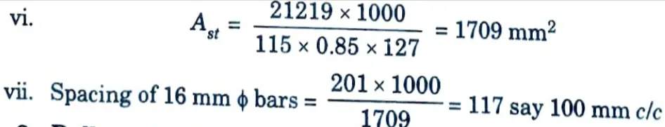
Since this steel is provided near both the faces, the spacing of the 10 mm ፨ɸ bars will be 320 mm c/c near each face.
4. Design of Short Walls :
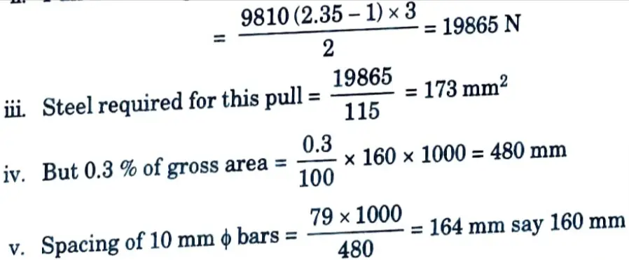
i. Consider a level one metre above the top of the haunch. The pressure intensity at this level
= 9810 (2.35 – 1) N/m2 = 13243.5 N/m²
ii. Effective span of the horizontally spanning slab
= 3 + 0.16 = 3.16 m
iii. Bending moment at corner section (i.e., ends)
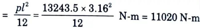
iv. Water pressure per metre height at this level, for one metre length of the long wall will be transferred to the short wall.
v. Tension transferred per metre height of short wall
= 13243.5 x 1 = 13243.5 N
vi. Resultant bending moment = M – Tx = 11020 x 1000 – 13243.5 (127 – 80) N-mm
= 10397560 N-mm
This bending moment produces tension near the water face.
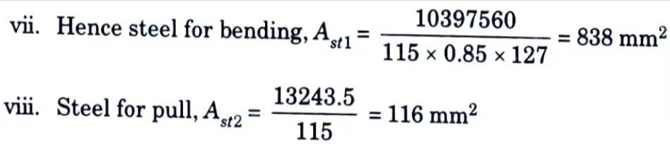
x. Total steel required, Ast = 838 + 116 = 954 mm2
Provide 16 mm ɸ bars @ 200 mm c/c.
5. Mid Span Tension :
i. Bending moment at mid span
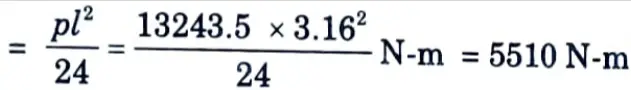
ii. Pull = 13243.5 N
iii. Resultant bending moment = M – Tx
= 5510 x 1000 – 13243.5 (127 – 80) N-mm
= 4887555.5 N-mm
This bending moment produces tension away from the water face.
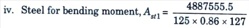
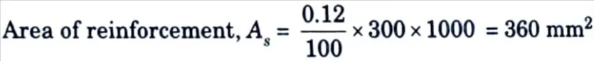
= 357.997 = 360 mm2
vi. Total steel required = Ast1 +Ast2 = 360 + 110 = 470 mm2
vii. Spacing of 16 mm bars
It is convenient to provide 16 mm ɸ bars @ 400 mm c/c which is just double the spacing of the bars provided near the corners.
6. Design of the Bottom one Metre Cantilevering Part of the Short Wall :
i. Maximum bending moment for cantilevering effect
i. Effective depth to the centre of 10 mm ɸ vertical bars
= 160 – 25 – 16 – 5 = 114 mm

vi. If the steel be provided near both the faces, the spacing will be at 320 mm c/c. But the requirement for cantilevering effect itself is 409 mm2.
vii. We will provide a spacing of 320 mm c/c away from the water face and a spacing of 160 mm clc near the water face.
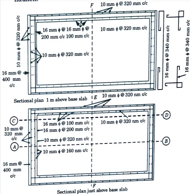
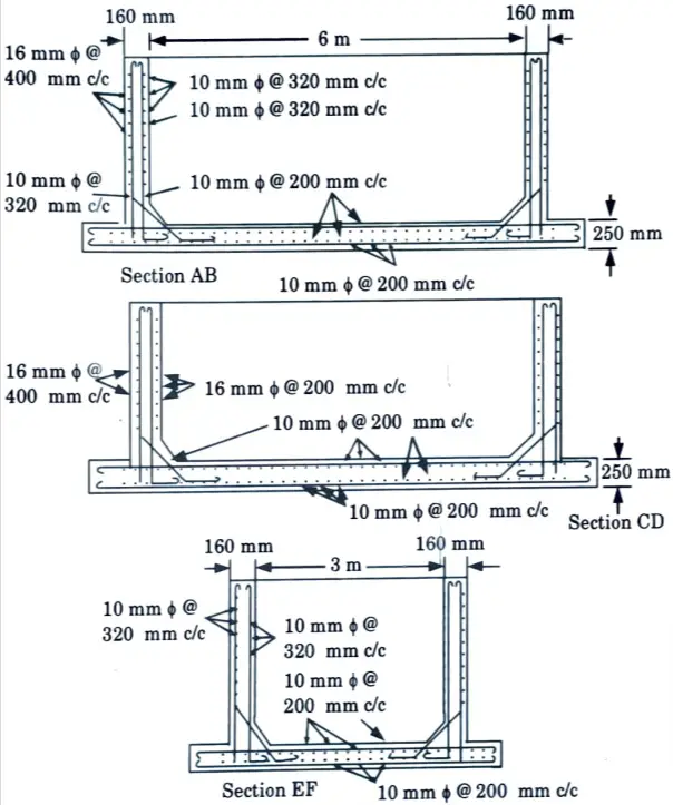
vii. Of these vertical bars near the water face alternate bars will be curtailed at a height of one metre above the haunch. Fig. 2 and Fig. 3 show the details of reinforcement.
7. Base Slab: The base slab may be made 250 mm thick with a top mesh and a bottom mesh of reinforcement with 10 mm ɸ bars @ 200 mm c/c.
Section 5: Aktu Sem 7 Questions of Advanced Concrete Design
a. Write the basic concepts of prestressed concrete.
Ans. Prestressing :
- 1. Prestressing is defined as applying a predetermined force or moment to a structural member in such a way that the combined internal stresses in the member caused by this force or moment and any anticipated condition of external loading are confined within specific limits.
- 2. In general, prestressing involves the imposition of stresses that are polar opposite to those caused by the subsequent application of working loads.
Concept of Prestressing :
- 1. In reinforced concrete, prestress is commonly introduced by tensioning the reinforcement.
- 2. So, compression is induced in the zones where external loads would normally cause tensile stresses.
- 3. Fig.(a) shows a prestressed concrete beam of rectangular section subjected to a prestressing force P, at the centroidal axis.
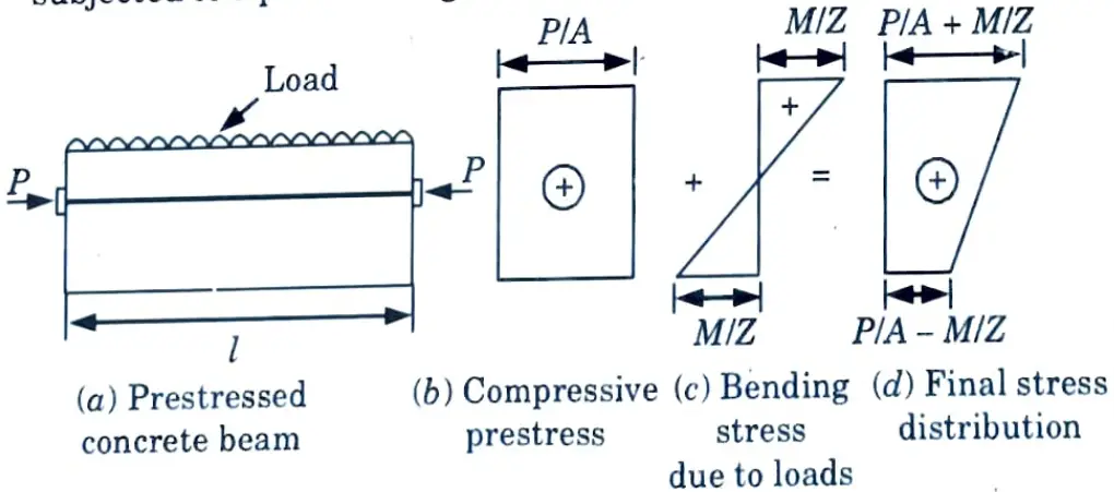
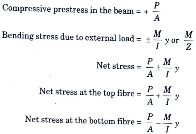
4. Due to this force, a uniform compressive stress P/A will be induced in concrete as shown in Fig.(b).
5. Under the action of loads, the stress at any point will be My/I and the stress diagram for the external loads is shown in Fig.(c).
6. The final stress diagram (d) shows that final stresses in the section are compressive only.
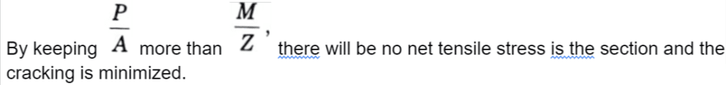
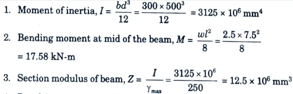
b. A rectangular concrete beam 300 mm x 500 mm with a span of 7.5 m is prestressed by a straight cable carrying an effective prestressing force of 400 kN, located at an eccentricity of 50 mm. If the beam supports a live load of 2.5 kN/m, calculate the resultant stresses at the central cross – section of the beam.
Ans. Given: Span of beam, L=7.5 m, Width of beam, b=300 mm, Depth of beam, d = 500 mm, Prestress force, P = 400 kN, Eccentricity, e = 50 mm, Live load = 2.5 kN/m
To Find: Resultant stress at the central cross-section.
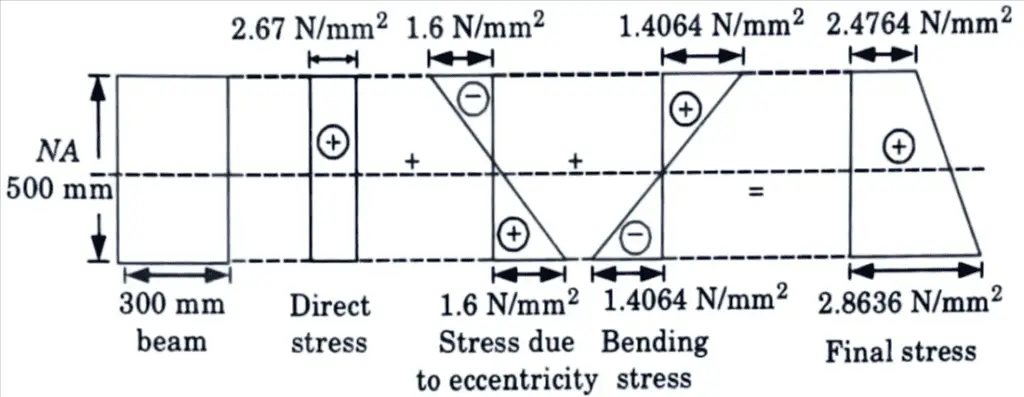
4. Resulting stress at top/bottom of mid section of beam is given by,
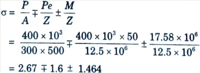
5. Stress at top fibre, σt = 2.67 – 1.6 + 1.464 = 2.4764N/mm2
6. Stress at bottom fibre, σ2 = 2.67 + 1.6 – 1.4064 = 2.8636 N/mm2
Section 6: Civil Questions of Advanced Concrete Design
a. Write the short notes on following :
i. Loss due to shrinkage of concrete.
ii. Loss due to friction for curvature effect.
Ans. i. Loss due to shrinkage of concrete :
i. Concrete shrinks because of drying and chemical changes. The shrinkage in concrete depends upon the quantity of water, aggregate, atmospheric conditions and time.
ii. The loss of prestress due to shrinkage is calculated as follows :
Loss of prestress due to shrinkage of concrete = Es x εsh
where, Es = Modulus of elasticity of steel.
εsh = Shrinkage strain.
t = Age of concrete in days. For pre-tensioning, εsh = 0.0003
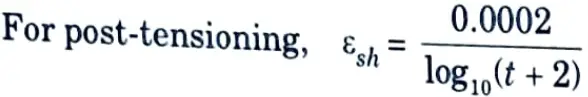
iii. For pre-tensioned member this loss is about 5 % and for post-tensioned member it is about 3 to 4 %.
ii. Loss due to friction for curvature effect :
i. Friction loss occurs in post-tensioned members only, due to friction in jacks, between the tendons and ducts or spaces etc.
ii. This loss can be reduced by lubricating the cables, applying prestress from both ends and avoiding large curvatures etc.
iii. This type of loss is due to :
a. The end curvature of the prestressed tendons which causes friction between the concrete and tendons.
b. The wave effect which is caused mainly due to misalignment of ducts.
iv. This loss can be calculated as follows :
Due to the curvature effect, if P0 is the prestressing force at jack end, then it reduces toPx at a distance x.
Px = P0e-μx
Similarly due to wave effect ;
Px = P0e-kx
Combining the effect of curvature and wave on the prestress;
Px = P0e-(μx + kx)
where, Px = Prestressing force at a distance x from the jack end in the direction of tangent to the curve.
P0 = Prestressing force at the jack end in the direction of tangent to the curve.
μ = Coefficient of friction (given in code IS 1343:1980).
∝ = Angle of curvature in radians of the cable (given in code IS 1343:1980).
K = Coefficient for wave effect as given in code IS 1343:1980.
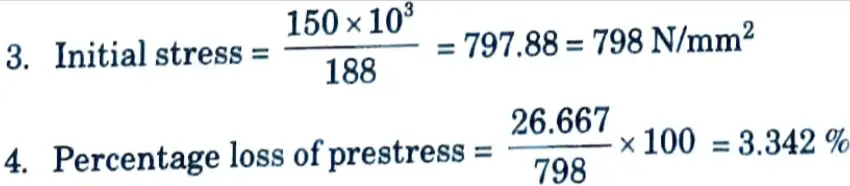
b. A pretensioned concrete beam , 150 mm wide and 300 mm deep, is prestressed by straight wires carrying a initial force of 150 kN at an eccentricity of 50 mm. The values Es and Ec are 210 kN/m² and 35 kN/m² respectively. Estimate the percentage loss of stress in steel due to elastic deformation of concrete if the area of steel wires is 188 mm².
Ans. Given: Width of beam = 150 mm, Depth of beam = 300mm, Initial force = 150 kN, Eccentricity, e = 50 mm, Es = 210 kN/m², Ec = 35 kN/m², Area of steel wire = 188 mm².
To Find: Percentage loss of stress in steel due to elastic deformation.
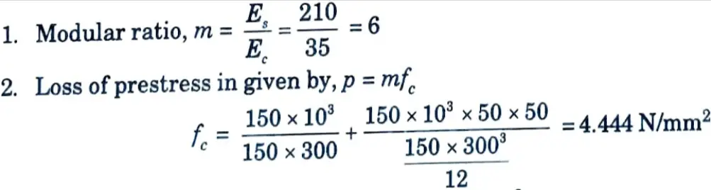
Loss of prestress,p = 6 x 4.444 = 26.667 N/mm2
Section 7: Important Notes, Question of Advanced Concrete Design
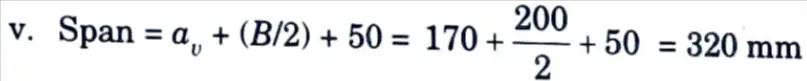
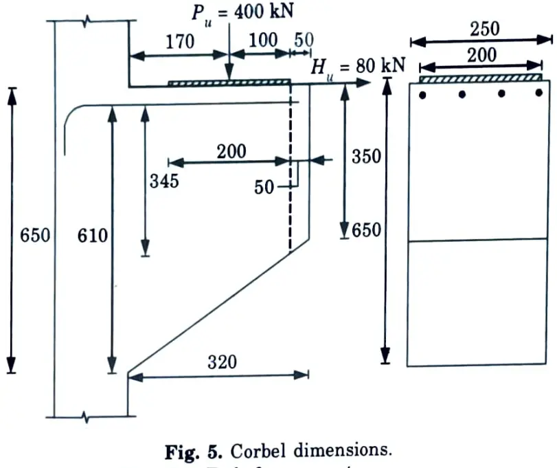
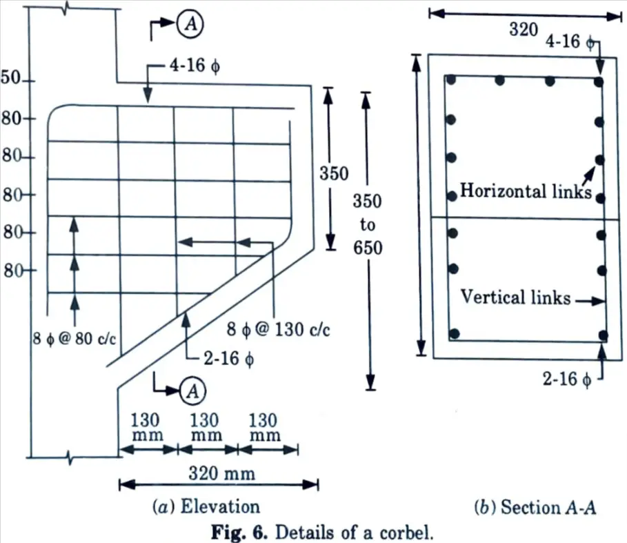
a. A corbel attached to a 250 mm x 250 mm RCC column, carries a factored load of 400 kN at a distance of 170 mm from the face of column. Design the corbel using M25 concrete.
Ans. Given: Factored load, Pu = 400 kN, Distance, av = 170 mm, Size of column = 250 mm x 250 mm and M25 concrete
To Find: Design of corbel.
1. Dimension of Base Plate :
i. Length of base plate = Width of column = 250 mm
ii. Bearing strength = 0.8 fck = 0.8 x 25 = 20 N/mm2

iv. The width of the plate also depends on geometric requirements keeping 50 mm projection on both sides. The width shall be
B = 100 + 50 + 50 = 200 mm
Provide 200 mm wide base plate with 50 mm edge cover.
vi. Use 16 mm thick base plate.
2. Depth (d) at Root of Carbel :
i. Maximum shear strength of concrete,

ii. Depth (d) at root of carbel is given by,
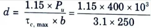
d = 593.55 ≃ 600 mm

iv. Let D = 650 mm, d = 650 – 30 – 10 = 610 mm
3. Depth (d1) Under Outer Face of Bearing Plate :

ii. Provide 350 mm depth at edge.
iii. Depth under outer face of base plate
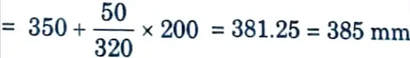
d1 = 385- 30 10 = 345 mm
4. Primary Tension Reinforcement :
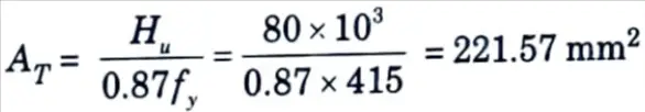
i. Horizontal force, Hu = 0.2 Pu = 0.2 x 400 = 80 kN
ii. Reinforcement for tension,
iii. Reinforcement for shear friction,

v. Equivalent moment on the section,
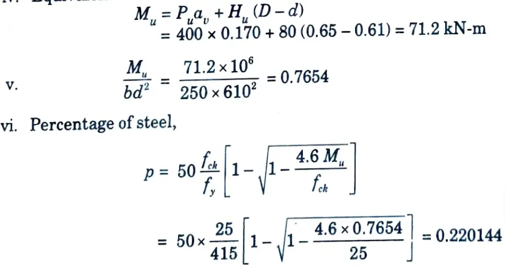
vii. Reinforcement for moment,
viii. Primary tension reinforcement is greater of
and AT + AM = 221.57 + 335.72 = 557.3 mm2
Hence Ast = 749.13 mm²
Provide 4- 16 ɸ same (Ast = 804.243 mm²)
Use 2-16 ɸ side and bottom bars to carry links.
5. Shear Reinforcement :
i. Horizontal Links :
a. Area of reinforcement, As = 0.5 Ast = 0.5 x 750 = 375 mm2
b. Use 8 mm ɸ 2 legged closed links, Asv = 100 mm²
c. Number of links = 375 / 100 = 3.75
Provide 4 closed links at 80 mm centres as shown in Fig. 6.
ii. Vertical Stirrups :
Use 8 mm ɸ 2 legged stirrups

b. Shear stress, τc = 0.51 N/mm²
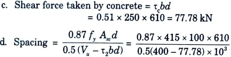
= 136.7 mm
Provide 8 mm ɸ 2-legged @ 130 mm c/c
b. Design a deep beam 300 mm wide and 4 m deep, simply supported over a span of 6 m. The beam carries a live load of 160 kN/m at the service state and is supported on walls of 600 mm thick on each end. Use M20 concrete and Fe415 steel having permissible tensile stress of 230 N/mm2.
Ans. Given: Width of beam, b = 300 mm, Depth of beam = 4000 mm Span of beam, l = 6 m, Service live load, wL = 160 kN/m, width of supporting wall = 600 mm, M20, Fe415.
To Find: Design a simply supported deep beam.
1. Effective Span :
i. Centre-to-centre distance between supports = 6000 + 600 = 6600 mm
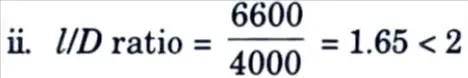
Hence it is deep beam.
iii. Effective span, l = 1.15 lc or c/c distance between supports, whichever is smaller.
l = 1.15 x 6000 = 6900 mm or 6600 mm
Effective span, l = 6600 mm
2. Positive Moment Reinforcement :
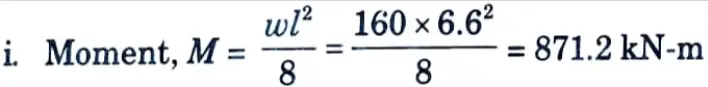
ii. Factored moment, Mu = 1.5 x 871.2 = 1306.8 kN-m
= 0.2(6600 + 2 x 4000) = 2920 mm
iv. Area of reinforcement,
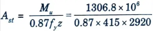
= 1239.5 = 1240 mm2
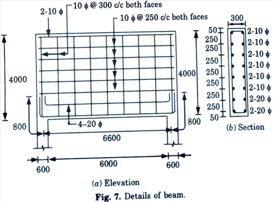
Provide 4 – 20 ɸ bars, (Ast = 1256 mm²)
v. The anchorage L0 beyond the centre of the supports is given by,
L0 = 0.8 Ld = 0.8 x 47.3 ɸ = 0.8 x 47.3 ɸ = 37.84 ɸ
= 37.84 x 20 = 756.8 mm
Provide 800 mm anchorage for 20 ɸ bars as indicated in Fig. 7.
Anchorage for upper layer is also satisfied.
vi. The positive reinforcement shall be placed within a zone
= 0.25 D – 0.05 l = 0.25 x 4000-0.05 x 6600 = 670 mm
Provide 2-20 ɸ in first layer at 50 mm and 2 -20 ɸ at 670 mm from tension face.
3. Side Face Reinforcement :
Since b > 200 mm provide side face reinforcement on both faces.
i. Vertical Reinforcement :
Provide 10 mm ɸ @300 c/c, both faces, As = 2 x 261.8 = 523.6 mm2
ii. Horizontal Reinforcement :

Provide 10 mm ɸ @ 250 mm c/c, both faces, As = 2 x 314.6 = 628 mm2
ii. At extreme compression side use 2-10 ɸ bars.
4. Reinforcement Details: The beam elevation and section are shown in Fig. 7.
1 thought on “Advanced Concrete Design: AKTU Solved Question Paper”