Use Quantum Notes to advance your structural analysis study. Learn important, often asked questions to prepare for your Aktu Btech examinations. With our assistance, succeed in your academic endeavours! Unit-2 Analysis of Trusses
Dudes 🤔.. You want more useful details regarding this subject. Please keep in mind this as well.

Important Questions For Structural Analysis:
* Aktu Quantum          * B.tech-Syllabus
* Circulars                     * B.tech AKTU RESULT
* Btech 3rd Year           * Aktu Solved Question Paper
Q1. Enumerate the different types of pinned jointed determinate truss with suitable example and sketches.
Ans. The following five criteria are the basis for the classification of trusses:
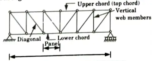
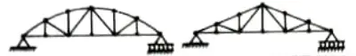
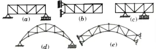
- 1. According to the Shape of the Upper and Lower Chords: The trusses can be divided into polygonal and triangular trusses, trusses with parallel chords as shown in Fig., or trusses with inclined chords as shown in Fig.
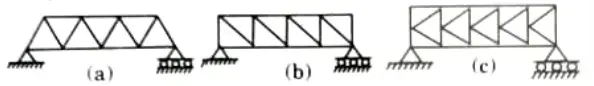
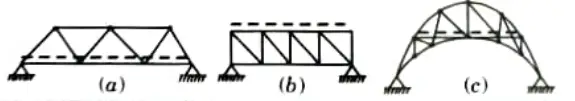
- 2. According to the Type of the Web: It allows for the division of trusses into those with triangle-shaped patterns, as shown in Fig. (a), those with quadrangular patterns, as shown in Fig. (b), produced by vertical and diagonal lines, and those whose web members form the letter K, as shown in Fig (c).
- 3. According to the Conditions of the Support: It enables the distinction between cantilever trusses, as shown in Fig. (b), trusses cantilevering over one or both supports, as shown in Fig. (c), and crescent or arched trusses, as shown in Fig. (d) and Fig (e).
- 4. According to their Purpose: The trusses may be classified as roof trusses, bridge trusses, those used in crane construction.
- 5. According to the Level of the Road:
- i. The trusses can be constructed so that the road is carried by the bottom chord joints as shown Fig.(a), or the upper chord joints as shown in Fig.(b).
- ii. Sometimes the road (lane) is carried at some intermediate level as shown in Fig.(c).
Q2. What are the methods available for the analysis of trusses ? Explain.
Ans. Different Methods of Analysis of Trusses: To analyze a statically determinate truss we have following two methods:
- 1. Method of joints.
- 2. Method of sections.
1. Method of Joints:
- i. If a truss is in equilibrium, then each of its joints must also be in equilibrium according to the method of joints.
- ii. Joint analysis should begin at a joint where there are no more than two unknown forces and at least one known force.
- iii. The member will be in compression if a force is pulling on the pin, and vice versa.
- iv. Always assume that the unknown member force operating on the joint’s free body diagram is in tension while solving a truss.
- v. If our presumption is accurate, the outcome will be favourable for member vi. Use the proper force’s size and direction on the joint’s subsequent free body diagram.
Procedure to Analyze:
- i. First, create a free body diagram of the complete truss and compute the external support responses.
- ii. Create a free body diagram of a joint that has no more than two unknown forces and at least one known force.
- iii. Pretend the unidentified member force is tensile in character, tugging on the joint.
- iv. The X and Y axes must now be positioned so that forces acting on the free body diagram can be simply broken down into their x and y components.
- v. Apply two force equilibrium equations 𝚺Fx = 0 and 𝚺Fx = 0. Solve these two equations to get unknown member force and then verify their correct directional sense.
- vi. Continue to analyze each of the other joints, where again it is necessary to choose a joint having atleast one known force and atmost two unknown forces.
2. Method of Sections:
- i. If the forces in only a few truss members need to be determined, the method of sections is typically utilised to do so.
- ii. The section approach divides the truss into two halves by passing a fictitious section through it.
- iii. The two components must both be in a balance.
- iv. Attempt to choose a section of the truss that is isolated and has no more than three unidentified force members.
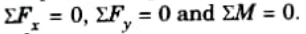
- v. Since only three independent equilibrium equations are present as:
Procedure to Analyze:
- i. To start, cut or choose the truss section where the forces are to be calculated.
- ii. Prior to choosing the section, it could be required to ascertain how the truss would respond from the outside.
- iii. Create free body diagrams for the chosen or sectioned truss with the fewest forces acting on it.
- Iv. Pulling on the member-joint pin with a tensile member force is acceptable.
- v. Calculate the moment’s sum at a place where the lines of action of two unidentified forces converge.
- vi. As two of the unknown forces are parallel, the third unknown force can be found by adding forces perpendicular to the direction of the parallel unknown forces.
Q3. Explain the concept of Zero-Force Members in a truss.
Ans. Concept of Zero-Force Member:
- 1. The member that supports no loading are termed as zero-force members.
- 2. Zero force members are used to simplify the truss analysis using the method of joints.
- 3. Zero force members are necessary for the stability of the truss during construction.
- 4. Zero force members are used to provide support if the applied loading is changed.
- 5. Zero force members occur in following two cases:
- i. If no external load is acting at a joint and the members joined at this joint are at any angle 𝜃 then force in both of the members must be zero in order to maintain equilibrium.
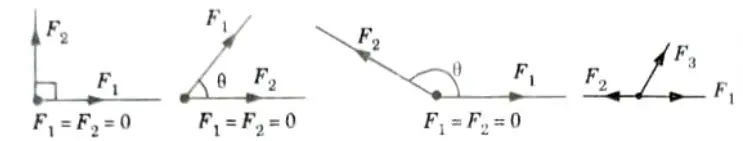
- ii. If no external force is acting on a joint having three members for which two of the members are collinear, the third member is a zero force member.
Here F3 = 0, as no force is acting in y-direction to balance it.
Q4. Analyze the truss shown in Fig.
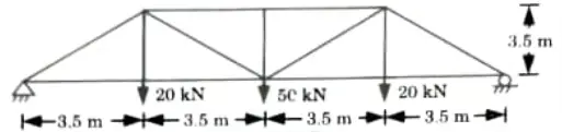
Ans.
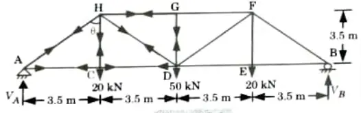
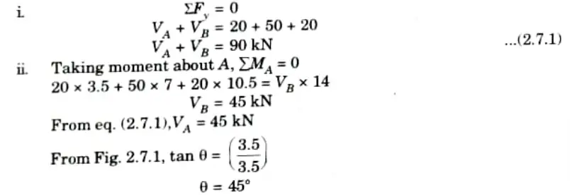
1. Reaction at Supports:
2. Joint A:
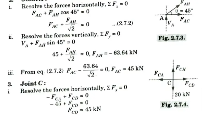
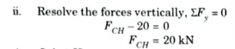
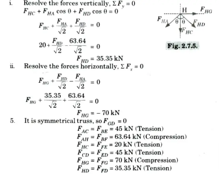
4. Joint H:
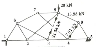
Q5. Determine the forces produced by the applied loads in members 49, 39, and 89 of the complex truss shown in Fig.
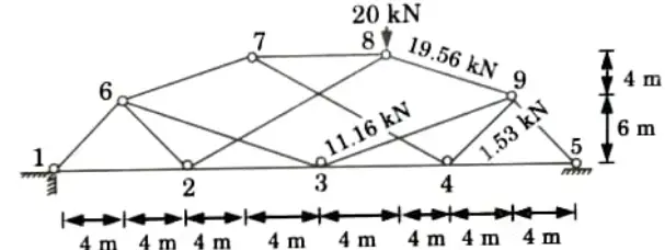
Ans.
- 1. The modified truss shown in Fig. is created by removing member 3-9, adding the substitute member 3-8, and applying the 20 kN load.
- 2. The member forces in the modified truss may now be determined; the values obtained are:
- 3. The 20 kN load is removed from the modified truss, and unit virtual loads are applied at nodes 3 and 9 in the direction of the line of action of the force in member 3-9.
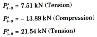
- 4. The member forces for this loading condition may now be determined; the values obtained are:
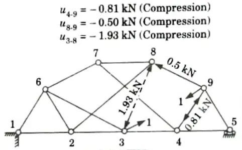
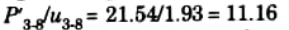
- 5. The multiplying ratio is given by:
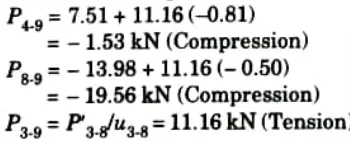
- 6. The final member forces in the original truss are:
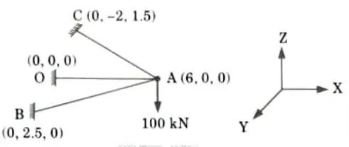
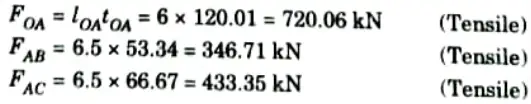
Q6. Determine the forces in the member OA, AB, AC shown in Fig. using tension coefficient method.
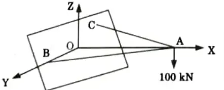
The co-ordinates of point A, B and C are (6,0,0) (0,2.5, 0) and (0,-2, 1.5) respectively.
Ans.
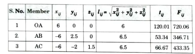
1. Step 1:To fix up bar parameter, the co-ordinates of the nodal joints are indicated. The bar parameters are tabulated in table.
2. Step 2: Writing of equilibrium equation, ‘
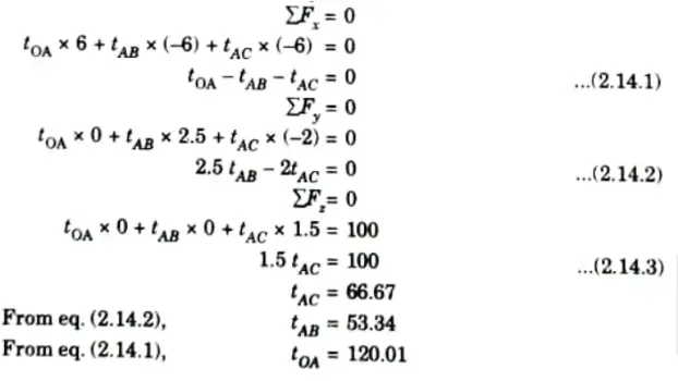
3. Force in member OA, AB and AC:

Structural Analysis Btech Quantum PDF, Syllabus, Important Questions
| Label | Link |
|---|---|
| Subject Syllabus | Syllabus |
| Short Questions | Short-question |
| Question paper – 2021-22 | 2021-22 |
Structural Analysis Quantum PDF | AKTU Quantum PDF:
| Quantum Series | Links |
| Quantum -2022-23 | 2022-23 |
AKTU Important Links | Btech Syllabus
| Link Name | Links |
|---|---|
| Btech AKTU Circulars | Links |
| Btech AKTU Syllabus | Links |
| Btech AKTU Student Dashboard | Student Dashboard |
| AKTU RESULT (One VIew) | Student Result |