
Structural Analysis Most Important Aktu Pdf Solved Question Paper , Notes, Quantum Pdf, Previously Repeated Solved Questions Important Topics 2022-23
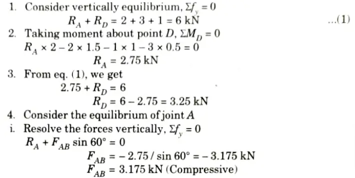
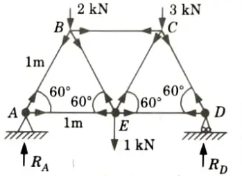
Dudes 🤔.. You want more useful details regarding this subject. Please keep in mind this as well.

Important Questions For Structural Analysis:
* Aktu Quantum          * B.tech-Syllabus
* Circulars                     * B.tech AKTU RESULT
* Btech 3rd Year
Section A: Structural Analysis Aktu Short Notes Pdf
a. Differentiate between determinate and indeterminate structures with example.
Ans.
| S. No. | Determinate Structures | Indeterminate Structures |
| 1. | The equilibrium conditions are sufficient for a thorough analysis of the structure. | Equilibrium conditions are insufficient for a thorough analysis of the structure. |
| 2. | No stresses are caused due to temperature changes. | Stresses are generally caused due to temperature variations. |
| 3. | No stresses are caused due to lack of fit. | Stresses are caused due to lack of fit. |
b. Determine the degree of kinematic indeterminacy for plane truss structure as shown in the Fig.
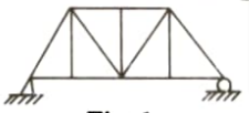
Ans. Given: Fig.
To Find: Degree of kinematic indeterminacy.

1. Number of joint, j = 8
2. Number of member, m = 13
3. Number of equilibrium equation, re = 3
4. Kinematic indeterminacy is given by, Dk = 2j – re.
Dk = 2 x 8 – 3 = 13
Dk = 13
Hence, it is a kinematic indeterminate structure.
c. With figure illustrate the classification of plane truss.
Ans.
- i. On the basis of utility of trusses:
- a Roof truss, and
- b. Bridge truss.
- ii. On the basis of the geometrical configuration:
- a. Simple truss,
- b. Compound truss, and
- c. Complex truss.
d. State the differences between a perfect truss and an imperfect truss.
Ans.
| S. No. | Perfect Truss | Imperfect Truss |
| 1. | Perfect trusses always retain their shape. | Imperfect trusses cannot retain their shape when loaded and get distorted. |
| 2. | Number of members in perfect truss are equals to (2j-3), where j is number of joints. | Numbers of members are either more or less than (2j -3). |
e. State the Betti’s law with proper expression.
Ans.
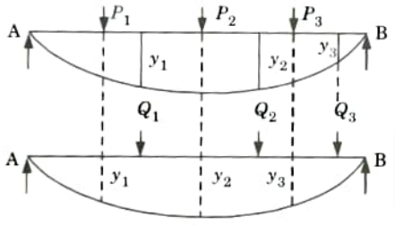
It is the generalized form of Maxwell’s law. For a structure whose material is elastic and follows Hooke’s law and in which the supports are unyielding and the temperature is constant, the virtual work done by a system of force P1,P2,P3 …… during the distortion caused by a system of forces Q1,Q2,Q3……. is equal to the virtual work done by the system of forces Q1,Q2,Q3……. during the distortion caused by the system of torches P1,P2,P3 ……
f. What is the importance of influence line diagram ?
Ans. Following are the uses of influence lines:
- i. Influence lines are used to depict how shear force and bending moment vary within a part that is being loaded or moved.
- ii. Influence lines provide guidance on where to place a moving load on a structure to maximise its influence at a given moment.
- iii. The related reaction, shear, moment, or deflection at the site can be determined using the ordinates of influence line diagram.
- iv. The structures on which the loads move over the span are designed using influence lines. The design of bridges, industrial crane rails, and conveyors, among other types of structures, are prevalent.
g. Define Muller-Breslau’s principal.
Ans. This concept states that “when the function acts on the beam, the influence line for the function (reaction, shear, or moment) is to the same scale as the deflected shape of the beam.”
h. What is radial shear and normal thrust in a three hinge arch ?
Ans. If 𝜽 be the inclination of any point X on the centre line of an arch, then the vertical shear Vx and horizontal thrust H would combine to produce aradial shear Rx and a normal thrust Nx at the section.
Then Rx = Vx cos 𝜽 – H sin 𝜽 and Nx = Vx sin 𝜽 + H cos 𝜽
i. Define Eddy’s theorem.
Ans. The bending moment at any section of an arch is equal to the vertical intercept between the linear arch and the central line of the actual arch.
Section B: Structural Analysis Quantum Pdf
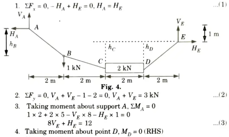
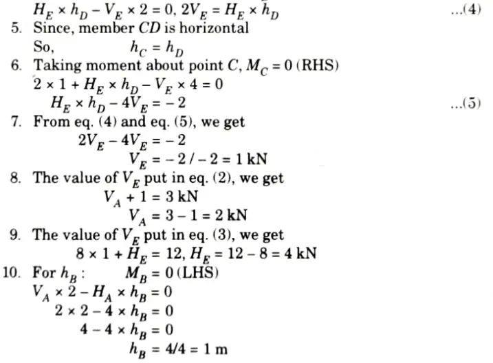
a. Calculate the support reactions and vertical sag at B wrt A. Member CD is rigid and horizontal.
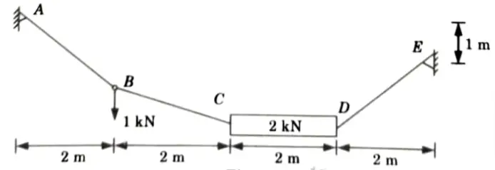
Ans. Given: Fig.
To Find: Support reaction and vertical sag at B wrt A.
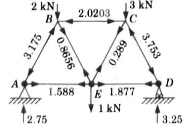
b. Determine the forces in the members of the Warren truss as shown in Figure by using method of joints. All members are 1 m long.
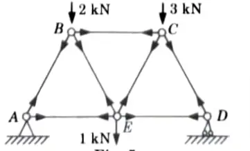
Ans. Given: Length of all member of truss = 1m,
To Find: Force in the member of truss.
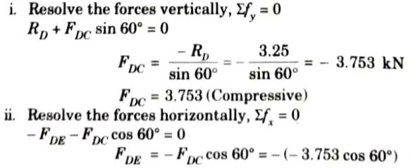
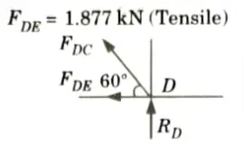
5. Consider the equilibrium of joint D:
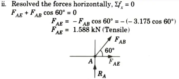
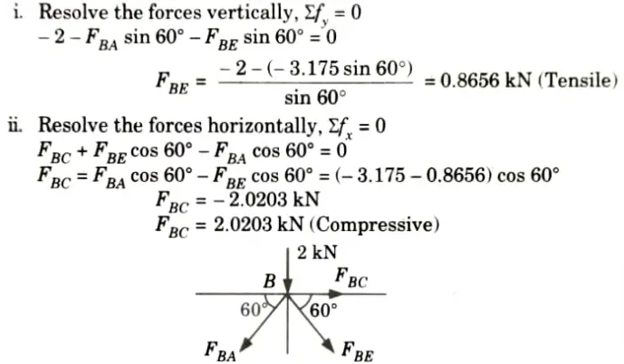
6. Consider the equilibrium of joint B:
7. Consider the equilibrium of joint C:
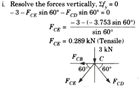
8. The results are shown in the Fig.
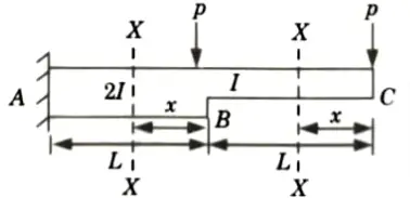
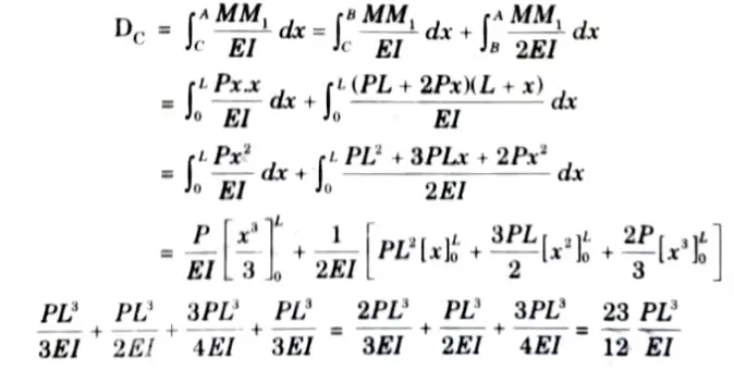
c. Determine the deflection of beam at the free end by using unit load method.
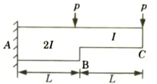
Ans. Given: Two point load = P, Span of beam = 2L.
To Find: Deflection of free end by unit load method.
1. Considering the beam into two segments BC and BA and with origin at C and B, respectively and measuring x as positive towards left, then the expressions for BM due to external loading and due to unit load applied at B is shown in following table:
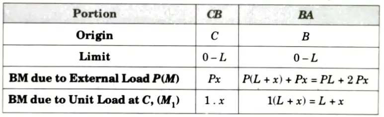
2. Deflection at C,
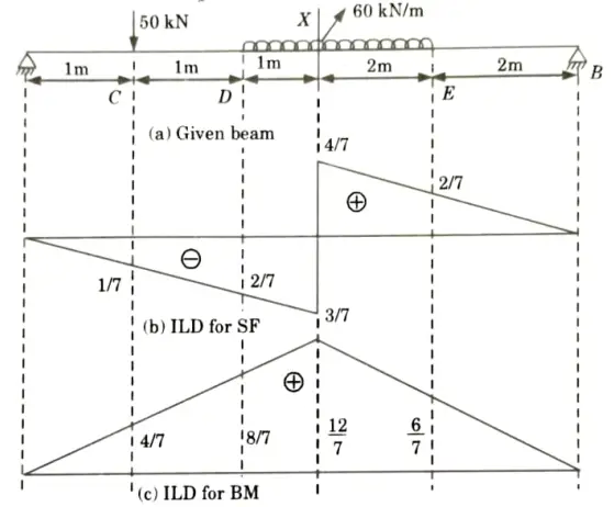
d. Find the shear force and bending moment at point X and also draw influence line diagram.
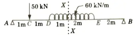
Ans. Given: Beam as shown in Fig.
To Find: Draw ILD of shear force and bending moment and value of SPF and BM at given section.
1. ILD for Shear Force at Section X-X
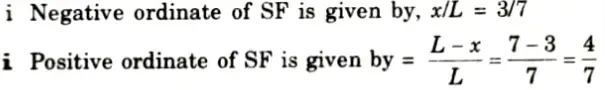
iii. Ordinate of ILD of SF at point C,
iv. Ordinate of ILD of SF at point D, yD
v. Ordinate of ILD of SF at point E, yE
vi. The value of SF at the section X-X =
2. ILD for BM at Section X-X:
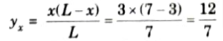
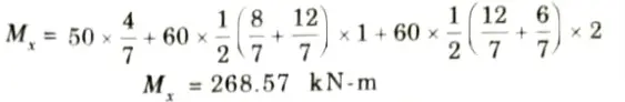
i. Maximum ordinate of ILD of BM at section X-X is given by,
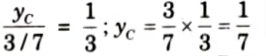
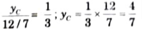
ii. Ordinate of ILD of BM at point C, yC
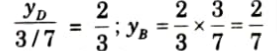
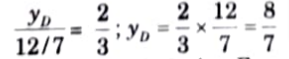
iii. Ordinate of ILD of BM at point D, yD
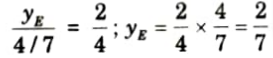
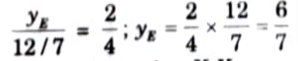
iv. Ordinate of ILD of BM at point E, yE
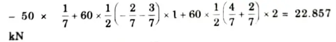
v. Bending moment at section X-X,
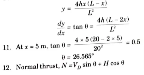
e. A parabolic three hinged arch carries load as shown in the figure. Determine the resultant reactions at support. Find the bending moment, normal thrust and radial shear at a distance of 5 m from A.
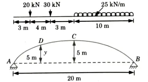
Ans. Given: Span of arch, L= 20 m
Rise, h = 5m, Intensity of ILD, w = 25 kN/m
To Find: Resultant reaction at supports, Bending moment, normal thrust and radial shear at a distance 5 m from A.
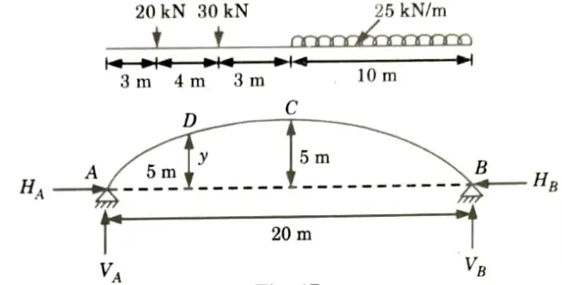
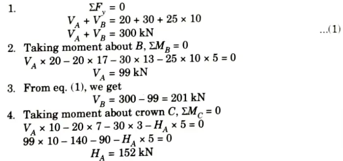
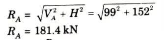
5. Resultant reaction at A,
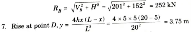
6. Resultant reaction at B,
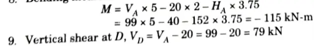
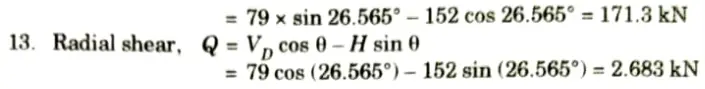
8. Bending moment at 5 m from the left support A,
10. Curve is given by,
Section 3: Aktu Important Notes of Structural Analysis
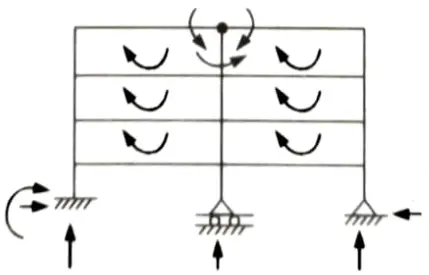
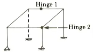
a. Find the static and kinematic indeterminacy of the structure as shown in the Fig.
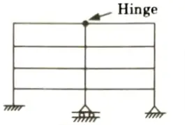
Ans. Given: Frame shown in Fig. Number of support reaction, R = 6, Number of close loop, C = 6
To Find: Static and kinematic indeterminacy.
1. Static indeterminacy is given by, Ds = Dse +Dsi
i. External static indeterminacy is given by,
Dse = R – 3 = 6 – 3 = 33
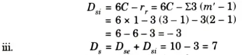
ii. Internal static indeterminacy is given by,
Dsi = 3C – r = 6 x 3 – (3 – 1) = 18 – 2 = 16
iii. Ds = 3 + 16 = 19
2. Kinematic indeterminacy is given by,

Number of support reaction, re = 6
Number of member, m = 20,
Number of member connected to internal hinge, m’ = 3,
Number of joint, j = 15
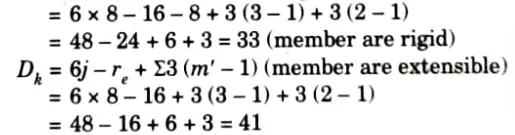
Dk = 3 x 15 -6 – 0 + (3 – 1)
= 41 (member are extensible)
Dk = 3 x 15 – 6 – 20 + (3 – 1) = 21 (member are rigid)
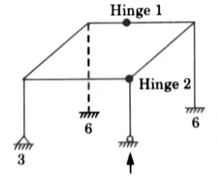
b. Find the static and kinematic indeterminacy of the structure as shown in the Fig.
Ans. Given: Frame in shown Fig. Number of support reaction, R = 16, Number of equilibrium equation in space truss, E = 6, Number of close loop, C = 1.
To Find: Static and kinematic indeterminacy.
1. Static indeterminacy is given by,
Ds = Dse + Dsi
i. External static indeterminacy is given by,
Dse = R – E = 16 – 6 = 10
ii. Internal static indeterminacy is given by,
2. Kinematic indeterminacy is given by,

Number of member, m = 8
Number of joint, j = 8
Number of support reaction, rc = 16
Member connected with internal hinge, m1 = 2, m2=3
Section 4: Aktu Repeated Questions of Structural Analysis
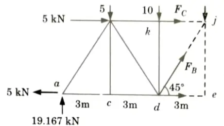
a. By using method of sections calculate forces at member A, B and C.
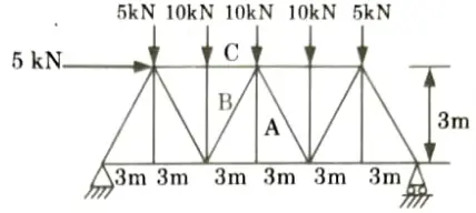
Ans. Given: Truss shown in Fig.
To Find: Forces in member A, B and C by method of section.
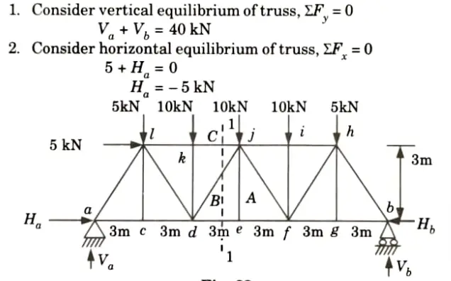
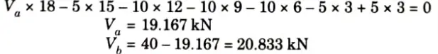
3. Taking moment about point b, Mb = 0
4. Draw a section 1-1 cutting the member kj, dj, de as shown in Fig. considered the equilibrium of left side portion of the truss.
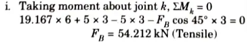
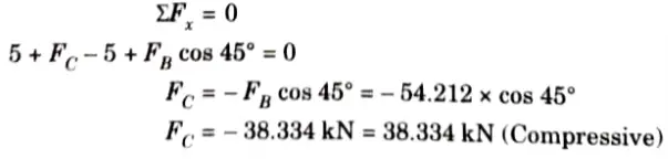
ii. Consider horizontal equilibrium,
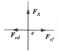
5. Consider equilibrium of joint e:
i. At the joint e, three forces (i.e., Fef, Fed, and FA) are acting, two of which (i.e., Fef and Fed) are along the same straight line. Hence the third force FA must be zero.
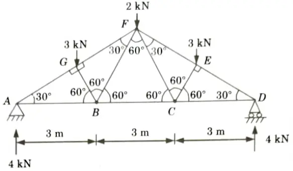
b. Determine the force in each member of the roof truss as shown. State whether the member are in tension or compression.
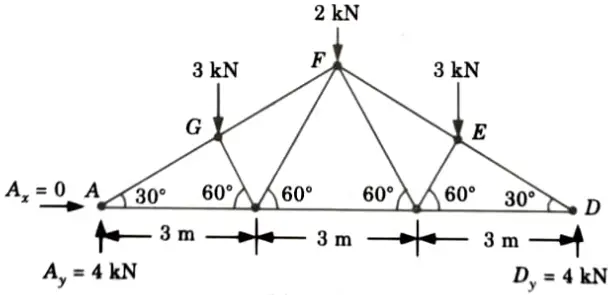
Ans. Given: Truss shown in Fig.
To Find: Forces in the members of truss.
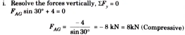
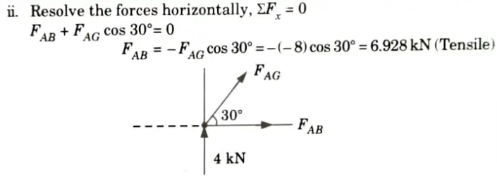
1. Considered the Equilibrium of Joint A:
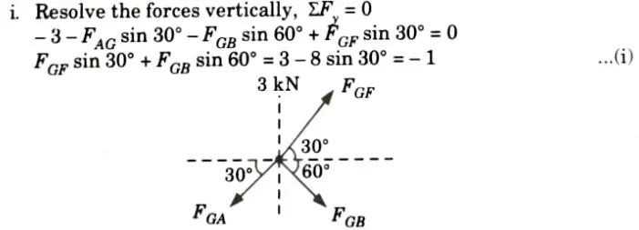
2. Consider the Equilibrium of Joint G:
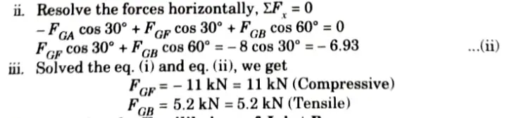
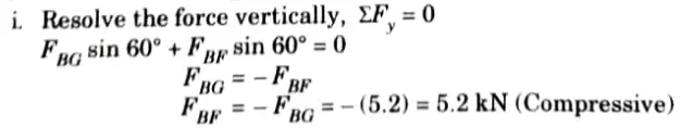
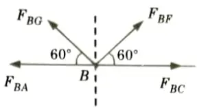
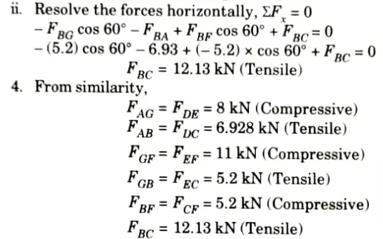
3. Consider the Equilibrium of Joint B:
Section 5: Quantum Pdf of Structural Analysis
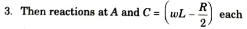
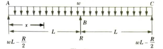
a. A continuous beam of two equal spans “L” is uniformly loaded over its entire length. Find the magnitude “R” of the middle reaction by using Castigliano’s theorem.
Ans. Given: Span of beam = 2L Load on beam = UDL of w kN/m
To Find: Reaction on middle support.
1. Let R be the redundant reaction at B.

4. At any point distant x from A,
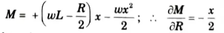
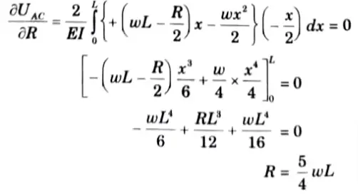
5. Substituting the values in (1), we get
b. Find slope at A and maximum deflection in the beam shown below by using conjugate beam method.
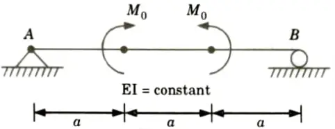
Ans. Given: Fig.
To Find: Slope at A, Maximum deflection.
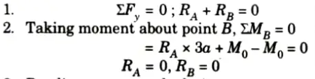
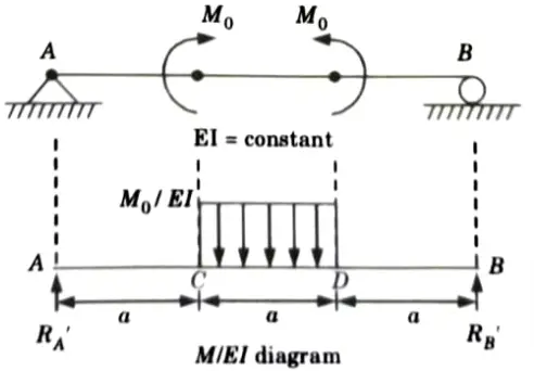
3. Bending moment calculation:
i. At just before C = RA x a =0
ii. At point C= RA x a +M0 = 0+ M0 = M0
iii. At just before point D = M0
iv. At point D = RA x 2a + M0 – M0 = 0
v. At point B, MB = 0
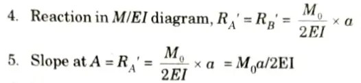
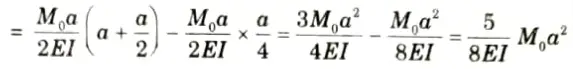
6. Maximum deflection at mid point,
Section 6: Aktu Quantum Notes of Structural Analysis
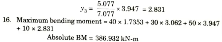
a. A train of four concentrated loads moves from left to right on a simply supported girder of span 16 m. Draw ILD for absolute maximum positive shear force, absolute maximum negative shear force and absolute maximum bending moment. Also calculate the values.
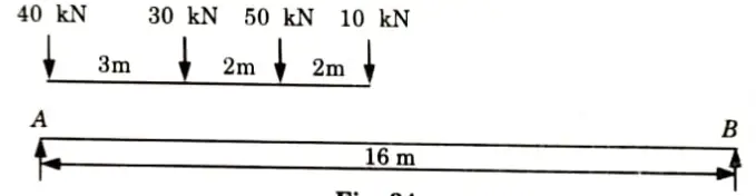
Ans. Given: Train loads= 40 kN, 30 kN, 50 kN, 10 kN, Span of beam, L= 16 m
To Find: Absolute positive and negative shear force and absolute maximum bending moment and draw ILD.
1. ILD for absolute maximum positive shear force at A as shown in Fig.
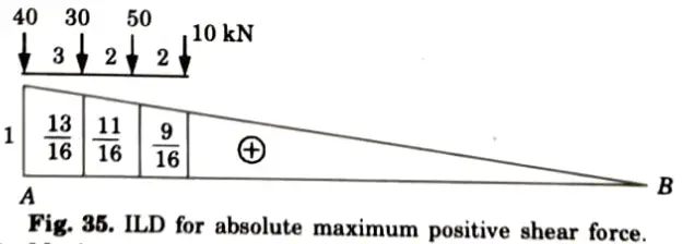
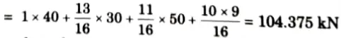
2. Maximum positive shear force
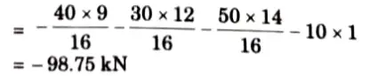
3. Maximum negative shear force occurs at B when leading load is on B.
4. Maximum negative shear force
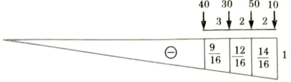
5. Try when 50 kN load at point B
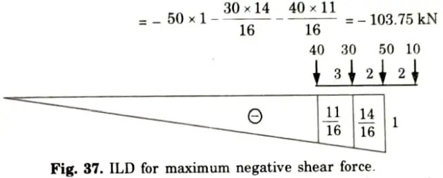
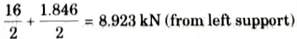
6. Finding position of loads on the section for absolute maximum moment, first position of C.G. of load system is to be located
7. Distance of C.G. for the leading load of 10 kN
8. It is nearer to 30 kN load and this load is lighter than another load of 50 kN. Hence maximum moment will occur under 50 kN load.
9. Distance between 50 kN load and the resultant,
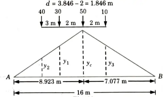
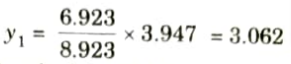
10. Position of 50 kN load for maximum moment =
11. For the section at 8.923 m from A, ILD for maximum moment is shown in Fig.

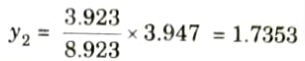
13. Ordinate under 30 kN load,
14. Ordinate of ILD under the load 40 kN
15. Ordinate of ILD under the load 10 kN
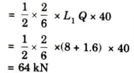
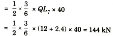
b. Draw the influence line diagram for forces in the members U3L4, U3U4 and U3L4 of the frame as shown in the Fig. Find the maximum forces developed, when uniformly distributed load of intensity 40 kN/m, longer than the span moves from left to right on bottom chord.
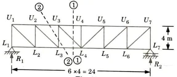
Ans. Given: Intensity of UDL = 40 kN/m, Span of truss, L = 24 m, Height of truss = 4 m.
To Find: Draw ILD and find value of force in member U3L4, U3U4, and U3L3.
1. Let the reactions at the left-end support and right-end supports be V1 and V2 respectively.
2. Take the section 1-1 as shown in the Fig.
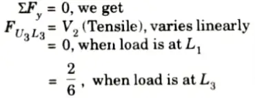
3. LD for FU3L4:
Which varies linearly.
= 0, when load is at L1
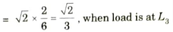
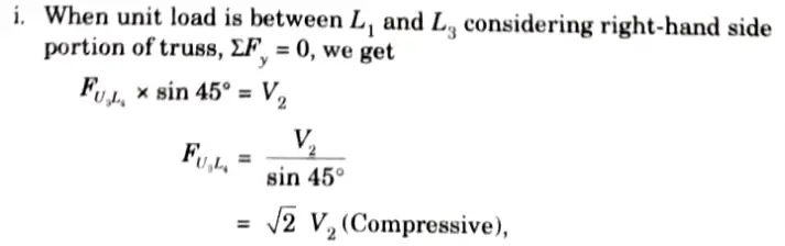
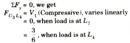
ii. When unit load is in portion L4 to L7 considering the equilibrium of left-hand side portion of truss,
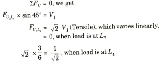
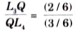
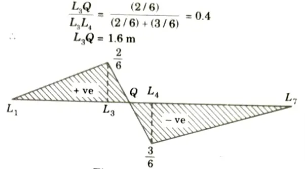
iii. Between L3 and L4 it varies linearly. Hence, ILD for FU3L4 is as shown in Fig. Let it intersect L3 L4 at Q. Then.
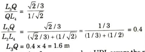
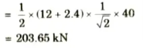
iv. Maximum compressive force occurs when UDL covers the portion L1Q,
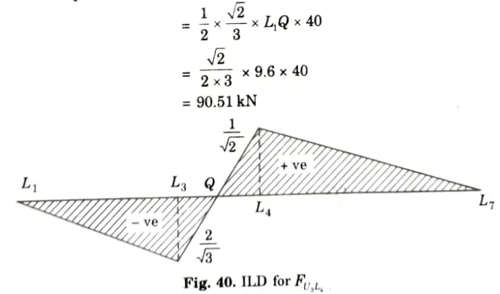
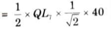
v. Maximum tensile force in the member U3L4 will occur when 40 kN/m UDL cover the portion QL7 and its value is
3. ILD for FU3U4:
i. Considering section 1-1 (Fig.) and moment equilibrium about L4 it can be observed that
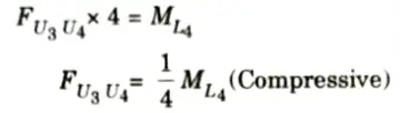
ii. Therefore, ILD for FU3U4 is similar to that of moment at L4 It is as shown in Fig. with maximum ordinate
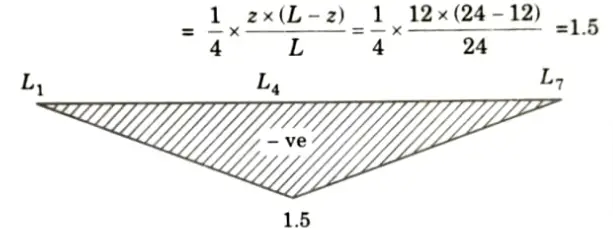
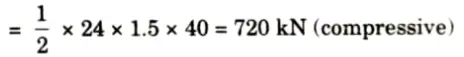
iii. Force in U3U4 is maximum when load covers the entire span and its value is
4. ILD for FU3L3:
i. Consider section 2-2, when the unit load is in portion L1L3 considering right-hand side portion,
ii. When the unit load is in portion L4L7 considering left-hand side portion,
Between L3L4 it varies linearly
iii. ILD is as shown in Fig.
iv. Maximum tensile force in U3L3 due to 40 kN/m UDL occurs when load covers the portion L1Q only and is
v. Maximum compressive force occurs when the load is in portion QL7 and is
Section 7: Structural Analysis Aktu Important Questions with Answers
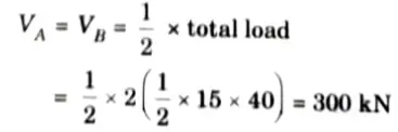
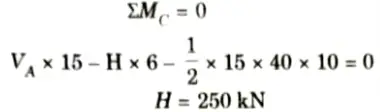
a. A symmetric three-hinged parabolic arch has a span of 30 m and a central rise of 6 m. The arch carries a distributed load which varies uniformly from 40 kN/m at each abutment to zero at mid-span. Determine:
i. The horizontal thrust at the abutments.
ii. Maximum positive bending moment in the arch.
Ans. Given: Span of three hinge arch, L = 30, Rise of arch, h = 6 m, Intensity of triangular load at abutment= 40 kN/m
To Find: Horizontal thrust and maximum positive bending moment.
1. The arch is shown in the Fig. Due to symmetry
2. Taking moment about central hinge,
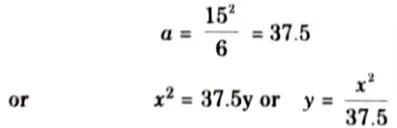
3. Taking origin at crown point C, the equation of parabola is given by,
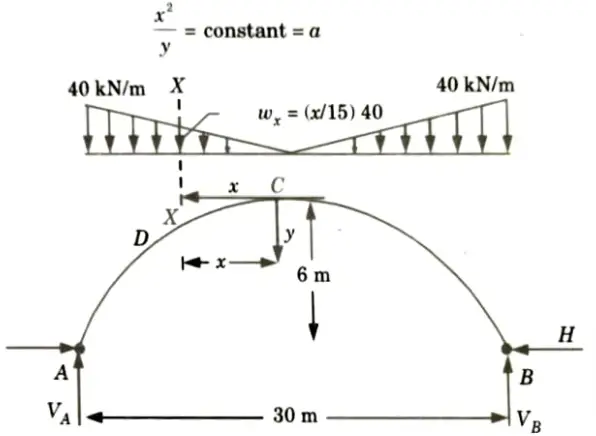
4. At x = 15 and y = 6
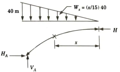
5. Reaction at crown is the horizontal force H. Hence, due to symmetry, there is no vertical shear (Fig.)
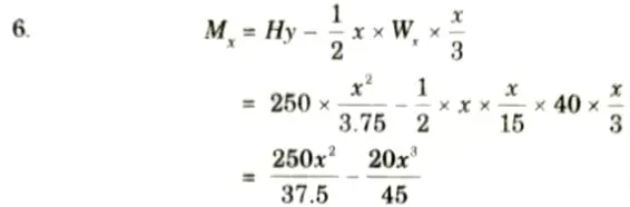
7. For maximum bending moment,
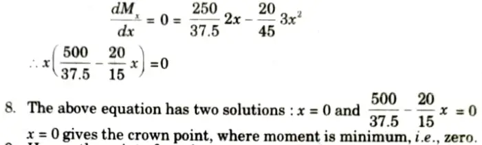
9. Hence, the point of maximum moment is given by,
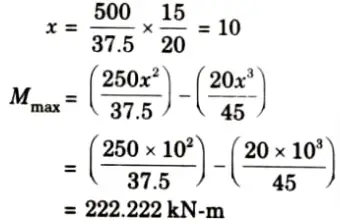
At x = 10m from crown, i.e., at 5 m from abutment.
b. Prove that the parabolic shape is a funicular shape for a three-hinged arch subjected to a uniformly distributed load over to its entire span.
Ans. 1. Let L = Span of the arch,
h = Central rise, and
w = UDL applied on the arch.
2. From symmetry we have,
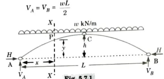
3. For horizontal thrust, taking moment about C,
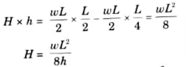
4. Let us now consider any section at distance x from A.
Equation of parabola is given by,
5. The value of bending moment at any section of the arch,

6. Hence a parabolic arch subjected to a UDL Over its entire span has the bending moment at any section zero. That is why the parabolic shape for three hinged arch is a funicular shape.
7 thoughts on “Aktu Previous Solved Structural Analysis Question Paper Quantum Notes Pdf”