In this Blog, we are exploring Unit5 Transient Behavior in Network Analysis and Synthesis -Btech AKTU Important questions with solution. Hope all Questions will help you in your upcoming exams.
Q1. Explain the concept of complex frequency?
ANSWER
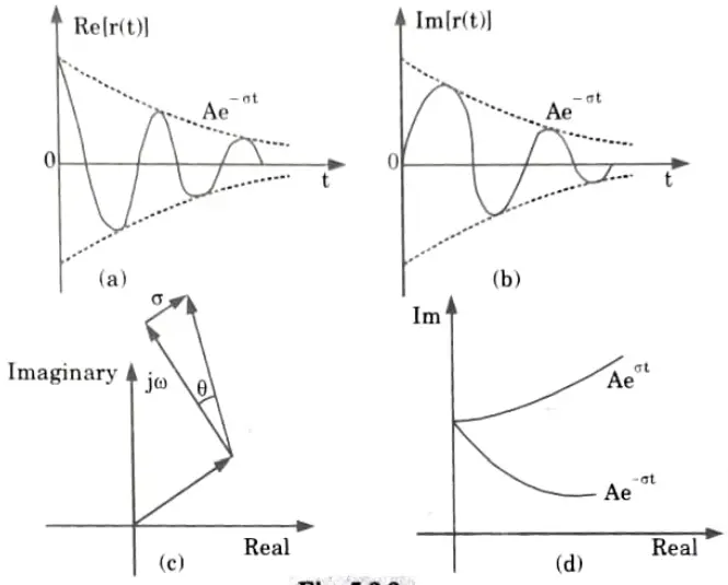
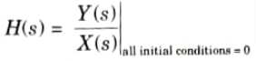
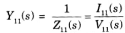
1. Complex frequency is a generalised frequency whose imaginary component represents the angular frequency and whose real component describes the increase or decay of signal amplitudes.
2. This complex frequency is applicable for cisoidal signals where
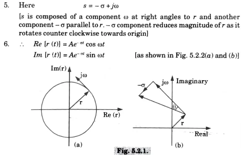
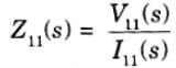
3.Since the velocity is also at a right angle to the phasor, the angular frequency o can be interpreted as a velocity at the end of the phasor r (t).
4. Let’s now investigate a case in which the velocity (represented by the symbol s) is inclined at an angle of 𝛉 as illustrated in Fig. 5.2.1. (b).
Q2. Explain the following terms:
i. Network functions
ii. Driving point functions
iii. Transfer functions
Answer
i. Network functions : The ratio of the Laplace transform of the response to the Laplace transform of the excitation, with all initial conditions set to zero, is the definition of the network function H(s) of a linear, time-invariant network.

Driving point function :These network functions are known as driving point functions when the excitation and response are defined at a single port.
There are two types of driving point function :
Driving point impedance function : It is described as the difference between the Laplace transforms of the voltage and current at the same port.
Driving point admittance function: The reciprocal of driving point impedance function is known as driving point admittance function.
Transfer function: Generally speaking, a transfer function connects a quantity at one port to a quantity at another port. It is a term used to define networks with two or more ports. The transfer function may have the following forms:
a Voltage transfer function: This is the ratio of voltage at one port to voltage at another port.
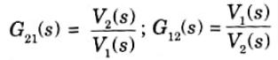
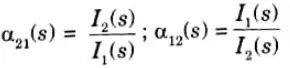
Current transfer function: this is the ratio of the current at one port to the current at another port.
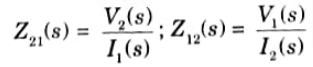
Transfer impedance function: This is the ratio of voltage at one port to current at another port.
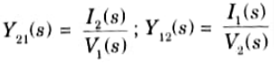
Transfer admittance function: This is the ratio of current at one port to voltage at another port.
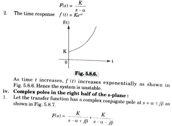
Q3. Obtain the relationship between various pole locations in s-plane and stability.
Answer
Poles on the negative real axis:
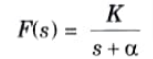
1. If the network has a simple pole on the negative real axis,
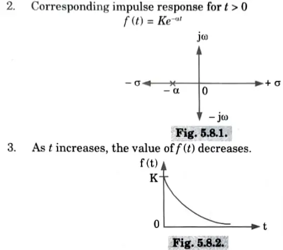
As the time t tends to increase, the response f(t) approaches zero hence the system is stable.
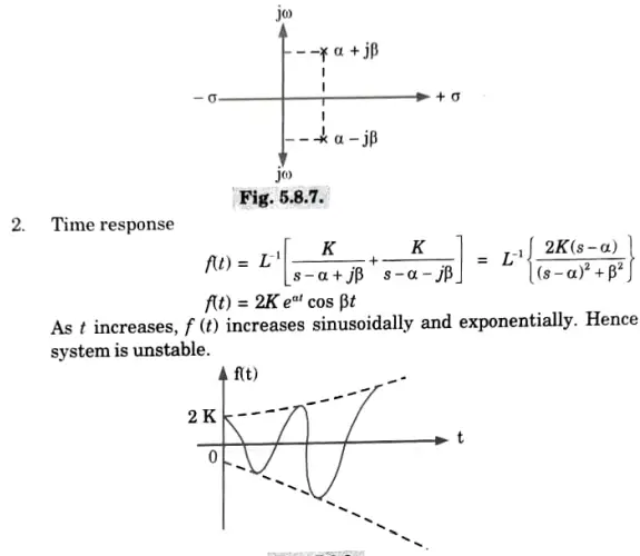
ii. Complex poles in the left half of the s-plane:
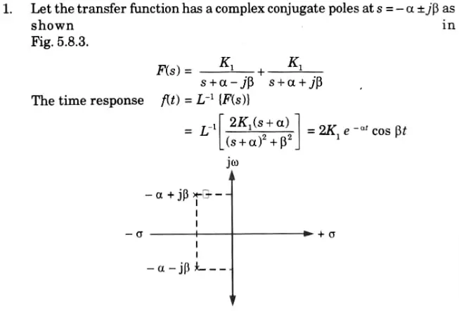
3.The time response is shown in Fig. 5.8.4.
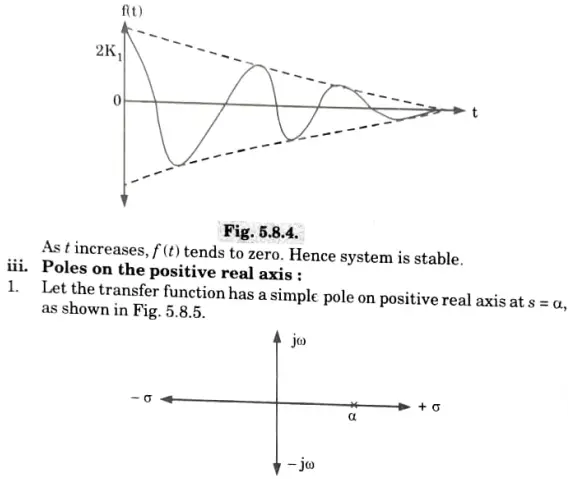
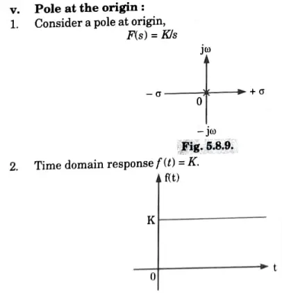
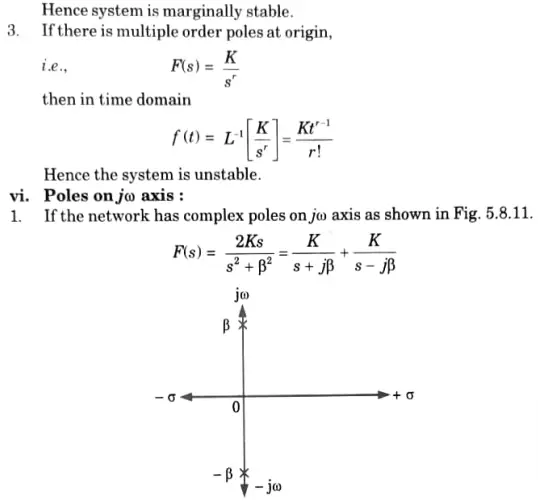
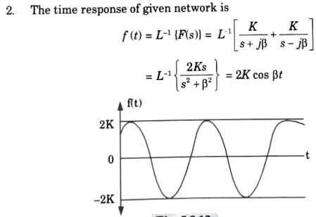
Hence the system is marginally stable.
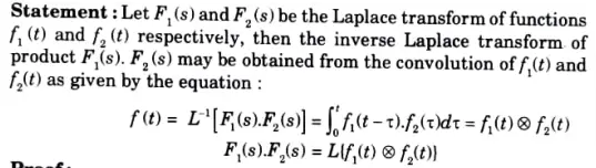
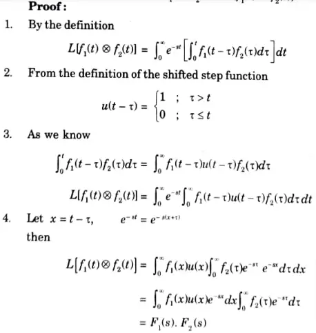
Q4. State and prove convolution theorem.
Ans.
Q5. Explain in detail the interconnection of all two-port networks.
Ans. i. Series connection:
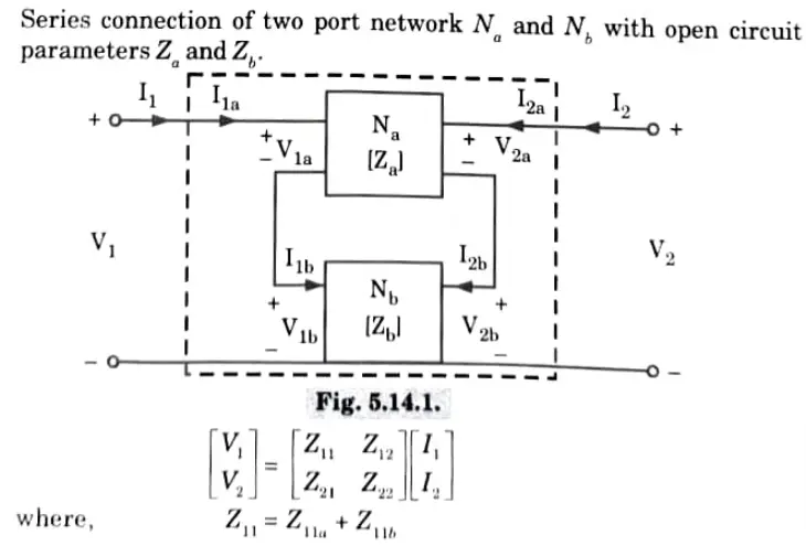
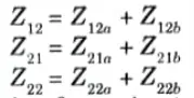
Z-parameter matrix of a series two-port network is the sum of the Z-parameter matrices of each individual two port network connected in series.
ii. Parallel connection:
Y-parameters matrix of parallel connected two-port network is the sum of the Y-parameter matrices of each individual two-port network.
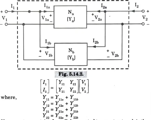
iii. Cascade connection:
T matrix for cascade connected two-port network is the matrix product of T-parameter of each individual two-port network.
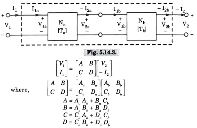
iv. Series-parallel connection:
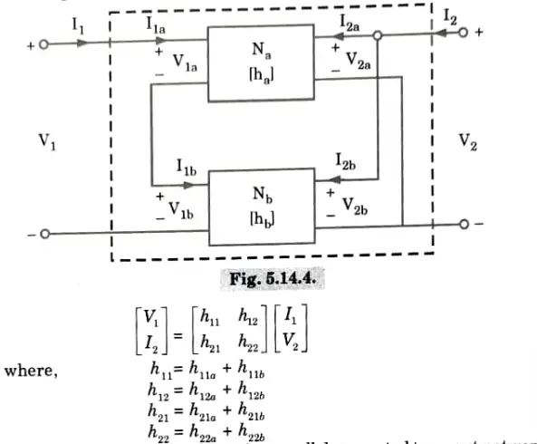
The h-parameters matrix for series-parallel connected two-port network is the sum of individual h-parameter of each two-port network connected.
v. Parallel-series connection:
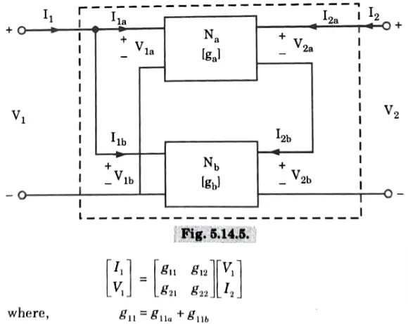
The g-parameter matrix for parallel-series connected two-port network is sum of g-parameter matrices of each individual two-port network connected.
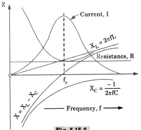
Q6. Explain resonance in a series RLC circuit with the help of impedance v/s frequency diagram and derive an expression for resonant frequency. Write properties and applications of series resonance circuits.
Ans.
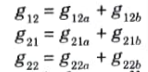
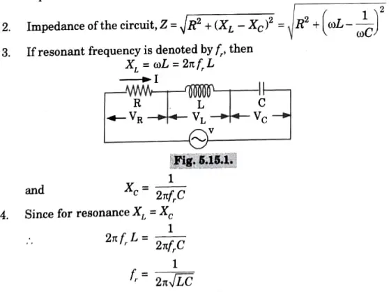
1 Consider an AC circuit containing a resistance R, inductance L and a capacitance C connected in series, as shown in Fig. 5.15.1.
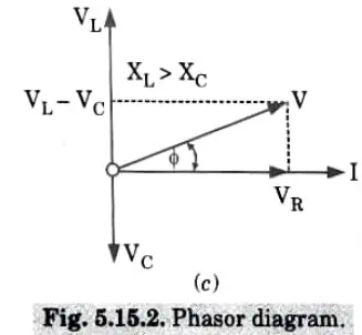
B. Property: At resonance,
1. Net reactance is zero, ie., X = 0.
2. Impedance of the circuit, Z = R.
3. The current flowing through the circuit is maximum and in phase with the applied voltage. The magnitude of the current will be equal to VIR.
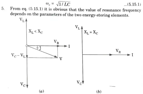
4. The voltage drop across the inductance is equal to the voltage drop across capacitance.
5. The power factor is unity.
C. Impedance v/s frequency diagram:
D. Applications of resonance:
1. Resonance circuits are used in tuning applications for radio and TV.
2. These circuits are also used in oscillators.

Network Analysis and Synthesis Important Links:
| Label | Link |
|---|---|
| Subject Syllabus | Syllabus |
| Short Questions | Short-question |
| Important Unit-1 | Unit-1 |
| Important Unit-2 | Unit-2 |
| Important Unit-3 | Unit-3 |
| Important Unit-4 | Unit-4 |
| Important Unit-5 | Unit-5 |
| Question paper – 2021-22 | 2021-22 |
Network Analysis and Synthesis Quantum PDF: | AKTU Quantum PDF:
| Quantum Series | Links |
| Quantum -2022-23 | 2022-23 |
AKTU Important Links | Btech Syllabus
| Link Name | Links |
|---|---|
| Btech AKTU Circulars | Links |
| Btech AKTU Syllabus | Links |
| Btech AKTU Student Dashboard | Student Dashboard |
| AKTU RESULT (One VIew) | Student Result |