In this Blog, We are discussing network analysis and synthesis notes aktu Important question for UNIT1. Hope you Beat Your Exams with the Most Important Network Analysis and Synthesis Unit 1 AKTU Questions.
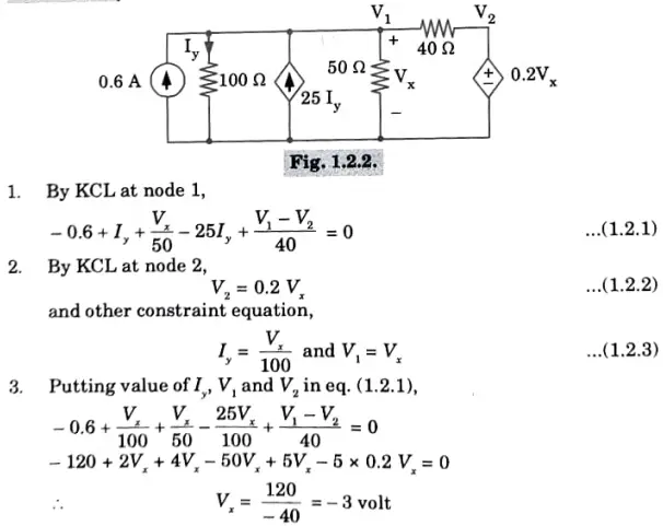
Q1. For the circuit shown in Fig., find the voltage VX using nodal analysis.
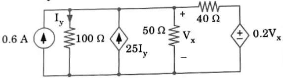
Ans.
2. Explain mesh analysis briefly.
Ans.
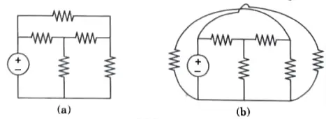
1. Only planar networks are suitable for mesh analysis. Mesh analysis is not applicable to non-planar circuits.
2. If a circuit can be drawn without crossovers on a plane surface, it is said to be planar. Without a crossover, a non-planar circuit cannot be traced on a plane surface.
3. Fig.(a) is a planar circuit and Fig.(b) is a non-planar circuit.
4.A loop that doesn’t have any other loops inside of it is referred to as a mesh.
5.We must first determine whether the circuit is planar before choosing mesh currents in order to use mesh analysis.
6. The final answer is obtained by expressing Kirchhoff’s voltage law equations in terms of unknowns and resolving them. The network of the circuit in Fig. 1.9.2 has two loops: abefa and bcdeb.
7. In circuit shown in Fig. 1.9.2, there are two loops abefa and bedeb in the network.
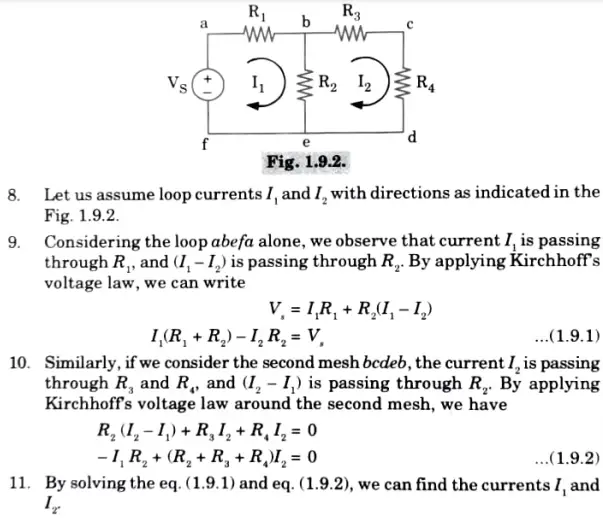
12.If we look at Fig. 1.9.2, the circuit has four nodes, the reference node included, and five branches. The quantity of mesh equations is equivalent to the number of mesh currents.
13. In general, the number of linearly independent mesh equations M = B- if we have N number of nodes, including the reference node, and B number of branches (N- 1).
3. How do you apply mesh analysis when there is a current source in a branch common to two loops? OR Explain the concept of supermesh analysis.
Ans.
- If any branch in the network that connects two loops contains a current source, it will be more challenging to apply mesh analysis in a straightforward manner.
- One way to overcome this difficulty is by applying the supermesh technique.
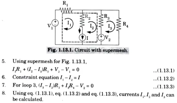
- A supermesh is made up of two neighbouring loops that share a current source, meaning it combines two adjacent meshes without taking into account the common branch where the current source is located.
- Think about the network in Fig. 1.13.1. Here, the common boundary between the two meshes 1 and 2 contains the current source I. Assume that VX is the voltage across the current source.
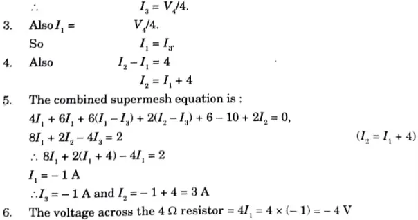
4. In the circuit shown in Fig., find the power delivered by the 10V source and the voltage across the 4 OHM resistor using mesh analysis.
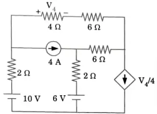
ANS.
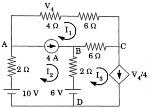
1. Since the 4 A current source is in a branch common to meshes 1 and 2,we use the supermesh techniques.
2. There is a current source in mesh 3,

5. Discuss source transformation technique for solving network.
Answer
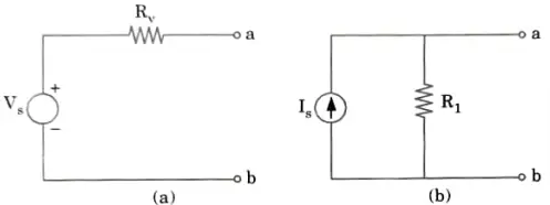
1. An ideal voltage source is connected in series with an internal resistance to form any practical voltage source. Similar to this, as shown in Fig. 1.20.1, a real current source consists of an ideal current source connected in parallel with an internal resistance.
2. RV and RI represent the internal resistances of the voltage source VS and current source IS, respectively.
3. Any source, be it a current source or a voltage source, drives currents through its load resistance, and the magnitude of the current depends on the value of the load resistance.
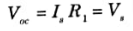
4. Fig. 1.20.2(a) and (b) represent a practical voltage source and a practical current source respectively connected to the same load resistance RL.
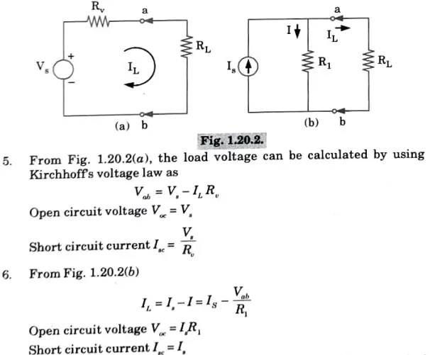
7. Here two sources (voltage and current source) are said to be equal, if they produce equal amounts of current and voltage when they are connected to identical load resistance.
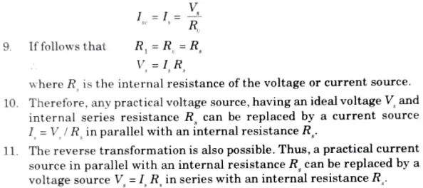
8. Therefore, by equating the open circuit voltages and short circuit currents of the two sources we obtain
6. What do you understand about the term ‘duality’ ? Discuss the procedure to find out the dual of a given network having both voltage and current sources. OR
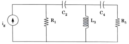
Draw the dual of the network shown in Fig
Answer
Duality
1 Currents and voltages are switched during a duality transition. If two phenomena can be expressed by the same mathematical Form or by equations, they are said to be dual.
2. The two loop-current method and node voltage method-based circuit analysis methodologies have a lot of parallels and analogies.
3.The fundamental elements and ideas of these two approaches, which are based on KVL and KCL, are duals of one another, with independent loops replaced by independent node pairs and voltage variables by independent current variables, etc. This resemblance is known as the “principle of duality.”
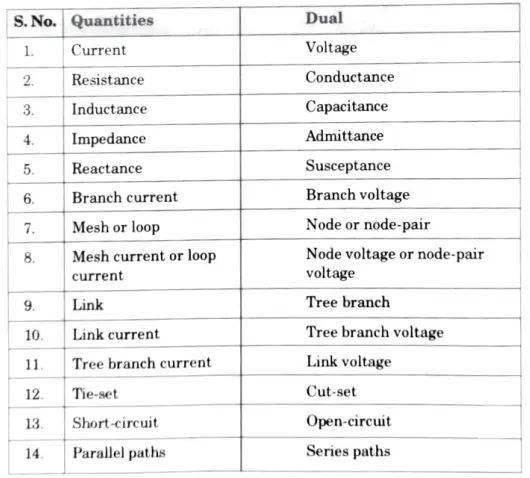
Dual quantities and concepts:
Construction of dual of a network:
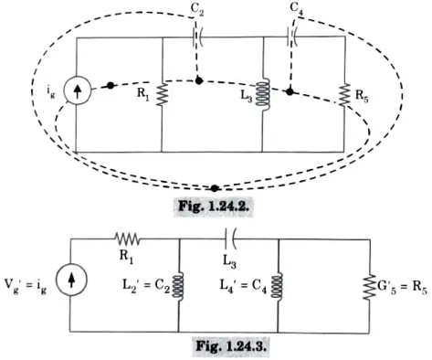
1.The non-reference nodes of the dual network are represented by the dots, which are positioned inside each independent loop of the supplied network.
2 The datum node is represented by a dot that is put outside the network. Dashed lines that cross the common branches join all internal dots together.
3.Dashed lines that cross all exterior branches connect each internal dot to the external dot.
Now replace all the crossed branch elements by its dual element.
Utility of dual networks : It makes it very easy to solve complex network problems.
Limitations of dual network:
1. Power has no dual due to its non-linearity.
2. Even when linearity applies a circuit element may not have a dual like mutual inductance.
Duality of network is shown in Fig. 1.24.3.

Network Analysis and Synthesis Important Links:
| Label | Link |
|---|---|
| Subject Syllabus | Syllabus |
| Short Questions | Short-question |
| Important Unit-1 | Unit-1 |
| Important Unit-2 | Unit-2 |
| Important Unit-3 | Unit-3 |
| Important Unit-4 | Unit-4 |
| Important Unit-5 | Unit-5 |
| Question paper – 2021-22 | 2021-22 |
Network Analysis and Synthesis Quantum PDF: | AKTU Quantum PDF:
| Quantum Series | Links |
| Quantum -2022-23 | 2022-23 |
AKTU Important Links | Btech Syllabus
| Link Name | Links |
|---|---|
| Btech AKTU Circulars | Links |
| Btech AKTU Syllabus | Links |
| Btech AKTU Student Dashboard | Student Dashboard |
| AKTU RESULT (One VIew) | Student Result |
3 thoughts on “Unit-1 network analysis and synthesis notes aktu”