
Btech AKTU Question Paper- 2021-22, Yes! Here we focus on Materials Engineering Question Paper with Answer – AKTU Btech 2021-22. Hope this article will help you for your AKTU Exams.
Section A: Short Question in Materials Engineering
a. Define unit cell in a crystal structure.
Ans. A unit cell is a small group of atoms arranged in three dimensions.
b. Differentiate between ductility and malleability.
Ans.
| S. No. | Ductility | Malleability |
| 1. | The term “ductility” describes a material’s capacity to stretch under tensile pressure. | Under compressive stress, a material’s malleability refers to its capacity to deform and alter shape. |
| 2. | Ductile material can be rolled into wires. | Malleable material can be rolled into sheets. |
| 3. | Measured by bend test. | Measure d by the ability to withstand pressure. |
c. Explain stress intensity factor.
Ans.
- 1. The stress intensity factor (K) is used in the field of fracture mechanics.
- 2. The magnitude ofK depends on :
- i. Sample geometry,
- ii. Size and location of the crack,
- ii Magnitude of load, and
- iv. Distribution of load.
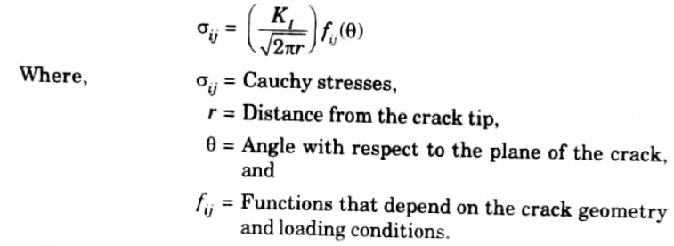
- 3. The fracture tip stress field is characterized by a single quantity known as the stress intensity factor.
- 4. The stress intensity factor, which is used to determine failure criteria due to fracture, represents the stress condition at a crack tip and is correlated with the rate of crack growth.
- 5. A crack front’s asymptotic stress and displacement fields surrounding a solid’s linear elastic solid are used to calculate the energy available for fracture.
- 6. This asymptotic expression for the stress field in loading is related to the stress intensity factor as given below,
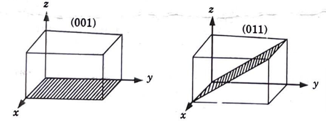
d. Draw the plane having miller indices (011) and (001).
Ans.
e. Explain Gibbs phase rule.
Ans.
- 1. The Gibbs phase rule offers a theoretical framework for describing a system’s chemical state and forecasting the equilibrium relationships of the phases that are present as a function of external factors like pressure and temperature.
- 2. It is expressed mathematically as follows:
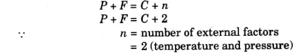
- 3. The quantity of independent external or internal variables, such as temperature, pressure, and concentration, that can be adjusted without causing a phase to dissolve or a new phase to form in the system is known as the number of degrees of freedom.
- 4. Temperature and pressure are regarded as external elements that affect the system’s condition when researching chemical equilibrium.
- 5. Pressure’s impact is disregarded when using the phase rule of two metal systems, leaving temperature as the only variable.. The equation will then be: F = C +1 – P
- 6. In equilibrium all factors have definite values, hence the degree of freedom cannot be less than zero
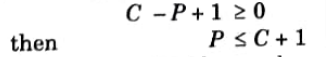
- which shows that the number of phases in a system cannot exceed the number of components plus one.
- 7. Therefore, no more than three phases may be in equilibrium ina binary system.
f. Discuss the use of phase diagram.
Ans. The uses of phase diagrams are as follows :
- 1. Understanding the characteristics of the materials in a heterogeneous equilibrium system can be done with the use of phase diagrams.
- 2. Phase diagrams can be used to examine low melting-point eutectic alloys that are utilised in soldering.
g. Define critical cooling rate.
Ans. The snout of the curve in a TTT diagram represents the transformation that takes the least amount of time. Critical cooling rate is the slope of the line that goes through this nose (C-curve).
h. Explain why tempering is required after hardening.
Ans. Tempering is performed after hardening since the parts produced cannot be utilised directly because to their high stress state, which may result in deformation and cracking when put or used at room temperature.
i. Differentiate between brass and bronze.
Ans.
| S. No. | Brass | Bronze |
| 1. | A metal alloy called brass is made of copper and zinc. | A metal alloy called bronze is made of copper and tin. |
| 2. | Often -bright golden in color. | Reddish brown in colour. |
| 3. | Aluminium and lead are sometimes also added. | Arsenic , phosphorous, aluminium, manganese and silicon are sometimes added. |
| 4. | It has a high degree of malleability. | It is hard and brittle. |
j. Describe superalloy and give its one example.
Ans. Superalloys are metal alloys that can function at high melting point fractions. They have excellent corrosion resistance, creep resistance, and mechanical strength.
Example: Waspaloy, Rene 150, HS188, CG27, etc.
Section B, Important Long Questions in Materials Engineering
a. Classify the defect in crystal and explain point defect in detail with neat sketch.
Ans.
A. Classification of Defect:
All defects and imperfections in crystals can be classified in following types:
a. Point Imperfections:
- 1. In a point defect, an atom is absent or is positioned irregularly inside the lattice structure.
- 2. These defects are completely local in effect.
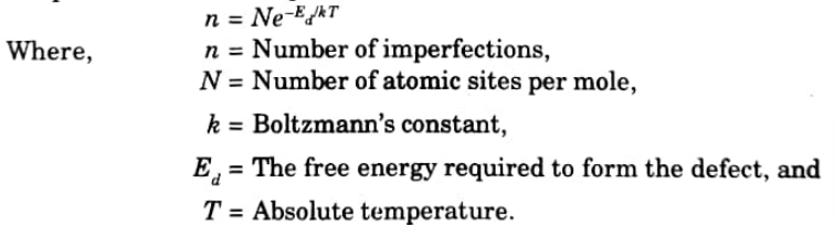
- 3. In crystals, point defects are invariably present, and their presence causes the free energy to diminish. The number of defects at equilibrium concentration at a certain temperature can be computed as,
b. Line Imperfection or Dislocations:
- 1. Dislocation is a linear disruption of the atomic arrangement that can very readily take place on the slip plane through the crystal.
- 2. A significant flaw in crystals is dislocation, a two-dimensional line fault. It is in charge of the slip phenomena that causes metals to deform.
- 3. The zone of localized lattice disturbances dividing a crystal’s slipped and unslipped regions may also be inferred as the cause of the phenomenon.
- 4. These are created during the metals’ plastic deformation throughout the solidification process, specifically during the occurrence of brittle fractures, creep, and fatigue, as well as strain hardening and yield points.
- 5. Causes of dislocation are:
- i. Thermal stresses or external stresses casing plastic flow.
- ii. Crystal growth.
- iii. Phase transformation.
- iv. Segregation of solute atoms causing mismatches.
- 6. There are two types of dislocation:
- i. Edge dislocations, and
- ii. Screw dislocations
- 7. The valuable property of ductility in metals, ceramics, and polymers is caused by these dislocations.
c. Surface and Grain Boundary Imperfections:
- 1. These two-dimensional flaws result from stacking faults, double boundaries, changes in how atomic planes are stacked on or across boundaries, etc.
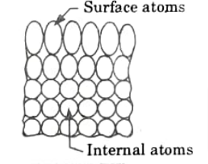
- 2. Due to the fact that the atomic bonds do not go beyond the material’s outside surface, it already has flaws.
- 3.These surface atoms have more energy than inside atoms because they are not completely surrounded by other atoms (Fig.).
- 4. While atoms inside the crystal have neighbours on both sides, surface atoms only have neighbours on one side.
B. Point Defect:
Different types of point imperfection are as follows:
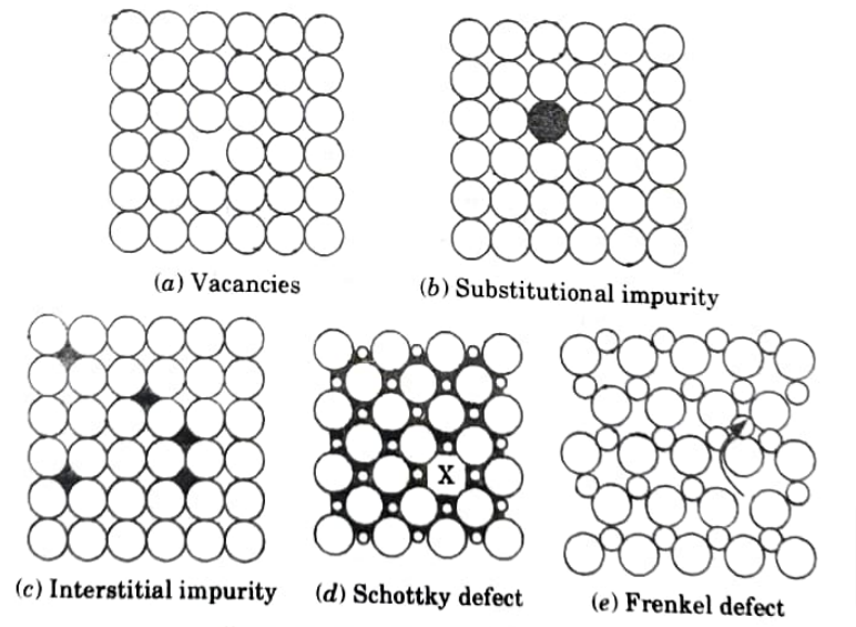
a. Vacancies:
- 1. A vacancy in a metal is the most basic type of point defect because it just involves one missing atom (Fig. 1.13.1). (a). Such flaws may stem from improper packing during the initial production.
- 2. Crystallization can occur when individual atoms move out of their lowest energy positions as a result of increased thermal energy. At greater temperatures, atoms’ thermal vibrations become more pronounced.
- 3. A single vacancy, two, or even three may combine to form a di-vacancy or tri-vacancy.
- 4. The lattice planes are distorted because the atoms next to a vacancy have a tendency to be closer together.
- 5. At thermal equilibrium, a crystal’s proportion of vacancies increases, increasing the structure’s unpredictability.
b. Impurities:
- 1 Impurities may produce compositional defects in the crystal structure.
- 2. Substitutional impurities are created when foreign atom impurities (Fig. 1.13.1(b)) occupy lattice locations where regular atoms are absent.
- 3. Interstitial defects will be produced by impurities like slag inclusions in metals that have atoms with smaller radii than the host atoms, as seen in (Fig. 1.13.1). (c).
- 4. These flaws lead to phase transition and atomic diffusion, which are significant factors in altering the thermal and electrical conductivity of metals and alloys.
c. Frenkel Defect:
1. A Frenkel defect is a kind of flaw in crystalline materials when an atom is moved from its lattice position to an interstitial site, leaving a vacancy at the old site and an interstitial defect at the new location within the same element with no alteration to the chemical composition.
d. Schottky Defect:
- 1. In non-ionic crystals Schottky means a lattice vacancy defect.
- 2. When ions with opposing charges leave their lattice positions in ionic crystals, vacancies are created. These vacancies are created in stoichiometric units to keep the ionic solid’s overall charge neutral.
- 3. These defects lead to a decrease in the density of the crystal.
b. Discuss following theories of failure in brief :
1. Maximum principal stress theory
2. Maximum shear stress theory
3. Maximum distortion energy theory
Ans. i. Maximum Principal Stress Theory (Rankine’s Theory) :
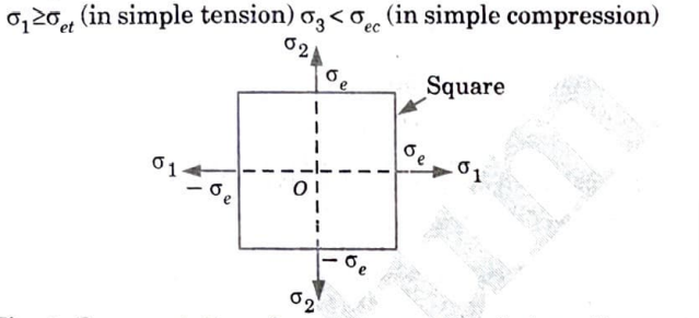
1. According to this theory, failure will occur when the maximum principal tensile stress (σ1) in the system reaches the value of maximum stress at elastic limit (σet ) in simple tension or minimum principal . stress reaches the elastic limit stress (σec) in simple compression.
ii. Maximum Principal Shear Stress Theory (Guest’s or Tresca’s Theory) :
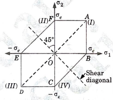
1. According to this theory, failure will occur when maximum shear stress τmax in the system reaches the value of maximum shear stress in simple tension at elastic limit.
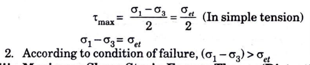
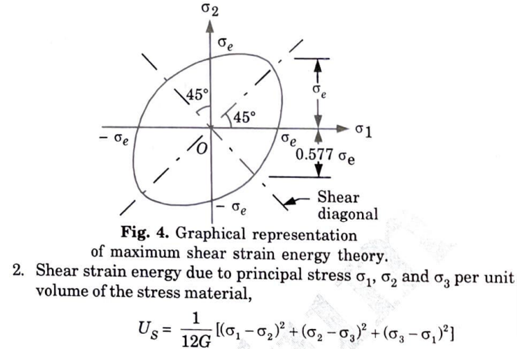
iii. Maximum Shear Strain Energy Theory (Distortion Energy Theory or Mises Hencky Theory) :
1. The shear strain energy per unit volume in the stressed material must match the shear strain energy per unit volume at the elastic limit point in the basic tension test for the hypothesis to hold true. At this point, the material fails.
c. Differentiate between alloy and solid solution. Also explain the Hume-Rothery rule for solid solubility in solid solution.
Ans. A. Difference between Alloy and Solid Solution :
| S. No. | Alloy | Solid solution |
| 1. | A metal or metal and another element combined to form an alloy. | A solid solution is a mixture of one or more solutes in a solvent that has solidified. |
| 2. | A metallic bonding characteristic identifies an alloy. A mixture of metallic phases or a solid solution of metal elements can both be an alloy (two or more solutions). | When the solvent’s crystal structure is unaltered by the addition of the solutes and the combination remains in a single homogenous phase, the mixture is regarded as a solution rather than a compound. |
| 3. | Alloys having a known stoichiometry and crystal structure are intermetallic compounds. | When the two relevant elements—usually metals—are close to one another on the periodic table, this frequently occurs. |
| 4. | Examples of alloys are steel, solder, brass, duralumin, bronze and amalgams etc. | Examples of solid solutions include crystallized sails from their liquid mixture, moist solids etc. |
B. Hume-Rothery’s Rule:
1 Hume-Rothery has given some criteria in alloy development for substitutional solid solution. These are known as Hume-Rothery’s Rules and are described below:
a. Chemical Affinity Factor:
- 1. Their solubility in solids is more constrained the more chemically similar two metals are to one another.
- 2. Two metals typically form an intermediate phase rather than a solid solution when their chemical affinity is high.
b. Relative Valency Factor:
- 1. The number of valence electrons per atom, or the electron ratio, will alter during alloying if the alloying element’s valence differs from the base metals.
- 2. A reduction in the electron ratio is more damaging to crystal structures than an increase. A lower valence metal may have good solubility for a higher valence metal, but a metal of high valence can only dissolve a small amount of a lower valence metal.
c. Relative Size Factor:
- 1. Two metallic atoms are said to have a favourable size factor for the production of solid solutions if their sizes differ by less than 15%.
- 2. Solid solution formation is typically strongly constrained and is only a tiny fraction of one percent if the size factor exceeds 15%.
d. Lattice Type Factor:
1. The only metals that can form an entire series of solid solutions are those with the same kind of lattice.
d. Explain the heat treatment and its objective. Also discuss the full annealing, normalizing and hardening process with help of Fe-C diagram.
Ans. A. Heat Treatment and its Objective :
a. Heat Treatment:
- 1. In order to achieve specific physical attributes linked to modifications in the nature, form, and distribution of the micro components, heat treatment is an operation that involves heating solid metals to predetermined temperatures, followed by cooling at appropriate rates.
- 2. In the numerous fabrication and manufacturing procedures, heat treatment is a crucial step.
b. Objective: The purpose of heat treatment is to achieve one or more of the following objectives:
- 1. to reduce internal stresses created during casting, welding, hot working, cold working, and other processes.
- 2. To improve machinability.
- 3. To soften metals for further treatment as wire drawing and cold rolling.
- 4. To improve mechanical properties.
- 5. To modify the structure to increase wear, heat and corrosion resistance.
- 6. To modify magnetic and electrical properties.
B. Full Annealing:
- 1. In order to increase a material’s ductility and decrease its hardness and make it more workable, annealing is a heat treatment technique that modifies the physical and occasionally chemical properties of the material.
- 2. Annealing consists of:
- i. Heating of steel above the critical temperature by 10 to 25 °C more than the lower critical temperature.
- ii. maintaining the steel at this temperature for a predetermined amount of time to allow for austenite to completely develop.
- iii. After that slowly furnace cooling is done at the rate of 25 to 15 °C/hour.
C. Normalizing:
- 1. When items are subjected to relatively high stresses, normalizing is usually used as the final heat treatment step.
- 2. In this procedure, steel is heated to a degree that is 40 to 50 °C over its upper critical temperature, held there for a brief period of time, and then cooled to room temperature in still air. Another name for this is air quenching.
- 3. This method is recommended for steels in the austenite range that are used in manufacturing processes like hot rolling and forging.
- 4. Additionally important are the removal of internal tensions that may have resulted from hot or cold working, the elimination of the carbide network at the steel’s grain boundaries, and the elimination of coarse grained structure in castings.
- 5. For hypoeutectoid steels, normalizing results in microstructures made of ferrite and pearlite, and for hypereutectoid steels, pearlite and cementite.
D. Hardening Process:
- 1. Steel that has been rapidly cooled after leaving the austenite phase is said to have hardened.
- 2. By submerging steel in a liquid bath, such as water or oil, fast cooling is achieved. Forced air can also be employed on occasion.
- 3. A meta-stable phase called martensite is created when steel is quickly cooled from the austenite phase.
- 4. Steel is quenched from a high temperature to a liquid bath at normal temperature, which is why hardening is also known as quenching.
- 5. In order to get the appropriate mechanical qualities after tempering, a steel must be hardened in order to increase its hardness, strength, and wear resistance.
- 6. For steel to be successfully hardened, two requirements must be met. First, homogenous austenite must form, and then austenite must cool quickly, undergoing a change into martensite.
- 7. When steel is heated to the proper austenitizing temperature and maintained at this temperature for a long enough period of time, homogeneous austenite begins to develop.
- 8. After homogeneous austenite has formed, steel is rapidly chilled by submersion in water or oil baths. As a result, martensite is produced.
e. Describe cast iron and discuss composition and application of Grey cast iron, malleable cast iron, white cast iron and spheroidal cast iron.
Ans. A. Cost Iron:
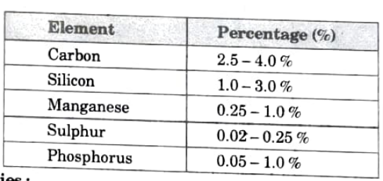
- 1. Cast iron is very useful engineering material. It contains more carbon percentage (approximately 2 % < C< 4.5 %).
- 2. Cast iron is created when pig iron, coke, and limestone are melted in a cupola furnace.
- 3. Coke acts as a fuel and limestone acts as flux.
- 4. Fluxes are used to separate the impurities from the pig iron (like oxides and fuel ash etc.).
B. Composition and Application of Grey Cast Iron, Malleable Cast Iron, White Cast Iron and Spheroidal Cast Iron :
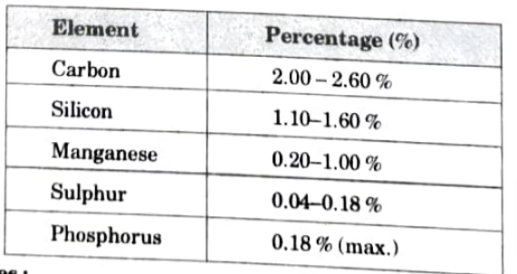
a. Grey Cast Iron:
i. Composition:
ii. Properties:
- 1. Tensile strength varies between 1500 and 4000 kg/cm2.
- 2. Hardness lies between 155 and 320 BHN.
- 3. Compressive strength is 3-4 times the tensile strength.
iii. Uses:
- 1. Engine cylinder block.
- 2. Flywheel, gear box cases etc.
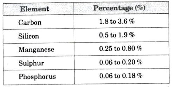
b. Malleable Cast Iron:
i. Composition:
ii. Properties:
- 1. It is the ductile iron.
- 2. demonstrates improved toughness fracture characteristics at low temperatures.
- 3. Easy castability.
iii. Uses: Steering brackets, hubs, crankshafts.
c. Spheroidal Cast Iron (SG Iron):
i. Composition:

ii. Properties:
- 1. The fluidity, castability, strength, toughness, wear resistance, pressure tightness, weldability, and machinability of this type of cast iron are extremely high.
- 2. It is suitable for complicated castings as well as large-scale castings because of its outstanding casting quality.
iii. Uses: Gear, cam shaft and crank shaft.
d. White Cast Iron:
i. Composition:
ii. Properties:
- 1. Excellent resistance to wear and abrasion.
- 2. Their high wear resistance is mostly due to the abundance of iron carbides in their structure.
iii. Uses: White cast iron serves as the raw material for malleable cast irons.
Section – C Important Questions Materials Engineering
a. Discuss the stress strain curve for steel and explain why steel is having ,two yield points. Also establish relation between the true stress and engineering stress.
Ans. A. Stress Strain Curve for Steel : Fig. shows stress vs. strain diagram for mild steel specimen. The following salient points are observed on stress-strain curve :

i. Limit of Proportionality (A): It is the maximum stress at which stress and strain are proportionate.
ii. Elastic Limit: This is the maximum amount of stress that can be applied to a material before strain fully vanishes and the material’s original length is restored. This point slightly exceeds the proportionality limit.
iii. Upper Yield Point (B): At this stress, the load starts to decrease and the extension starts to rise. This occurrence is known as material yielding.
iv. Lower Yield Point (C): At this point, the stress is constant, but the strain is temporarily increased.
v. Ultimate Stress (E): The maximum tension that the material can withstand is this. At this point, a specific section’s cross-sectional area starts to decrease quite quickly. Neck formation is the term for this.
vi. Breaking Point (F): The stress at which finally the specimen fails is called breaking point.
B. Reason for Having Steel as Two Yield Points :
- 1. Steel is made up of atoms of nitrogen and carbon at atmospheric pressure. In the crystal structure of steel, this carbon and nitrogen formed like a dislocation plane.
- 2. It needs more load to get displaced. a result upper yield point appears.
- 3. When something is dislocated, it takes some time for it to settle in the interstitials, which reduces the need for more load and causes lower yield points to occur.
- 4. Therefore, we can say;steel has two yield points.
C. Relation between the True Stress and Engineering Stress :
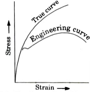
- 1. In tensile test, as the test progresses, one region of the specimen begins to deform much quicker than the rest.
- 2. Stress is calculated using the area’s decrease over the course of the test.
- 3. Engineering or nominal stress is the term used when the stress is determined based on the original area.
- 4. If the original length is used to calculate strain we get the engineering strain.
- 5. The actual area of the load at any given time can also be used to calculate stress. This is referred to as genuine stress.
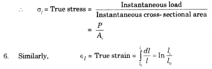
Where, dl is the infinitesimal elongation.
- 7. When the mechanism of work hardening, the interaction of mobile dislocation with one another, is taken into account, the real stress-strain curve always exhibits a continuously rising characteristic.
- 8. The start of necking coincides to the engineering curve’s maximum strength. The curve falls as a result of the necking-related rapid area reduction. When using the actual stress-strain curves, this does not occur.
- 9. It is not useful to utilise the full specimen length to determine deformation since strain is not homogenous after necking starts and when one area of the specimen is elongating more than the rest.
- 10. True strain can be expressed in terms of area by substituting in the equation:

- 11. While real stress-true strain diagrams are rarely needed, the majority of practical diagrams are based on engineering stress vs engineering strain.
b. A component having length of 1 m was loaded beyond elastic limit. At a point when its length increased by 3 mm. It was. experiencing stress of 250 l\’IPa. If the Young’s modulus of the material is 200 GPa. What will be the final dimension of the component after unloading?
Ans. Given: ▽l = 3 mm l = 1 mσ = 250 MPa, E= 200GPa
To Find: Final dimension.

Important Long Questions in Material Engineering
a. Explain Griffith theory for brittle fracture and formulate the expression for critical crack size.
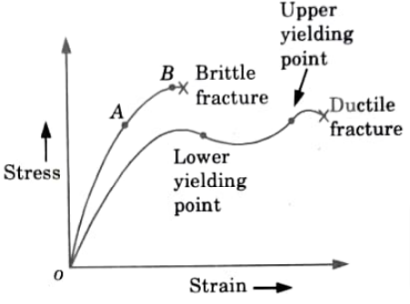
Ans. A. Brittle and Ductile Fracture:
- 1. (Fig.) shows the stress-strain diagram for the ductile and brittle fracture of material.
- 2. From o to A, proportional limit is prevailed i.e., material regain its original position if stress is removed.
- 3. If more stress is applied at point B, yield point is reached, and the brittle fracture takes place at this point.
- 4. Due to their greater elastic properties, ductile materials can be stretched until they reach an upper yielding point.
- 5. When stress levels are raised over the upper yielding point, ductile fracture occurs as a result of the material breaking.
B. Griffith’s Criterion:
- 1. Griffith has proposed a standard for how pre-existing cracks in fragile materials spread.
- 2. The crack may have been caused by a cluster of dislocations, a solidification fault, or a surface scratch, among other things.
- 3. The material on either side of the crack can no longer store elastic energy as the crack lengthens because tensile stress cannot be transferred across the crack. Therefore, the release of elastic energy is correlated with an increase in fracture length.
- 4. Griffith proposed that a fissure would grow once the elastic energy produced by extending it was equivalent to the surface energy needed to do it.
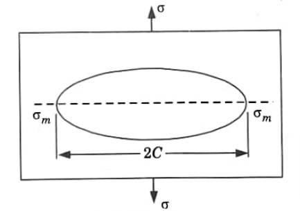
- 5. For an elliptical crack (Fig.), the maximum stress at the tips is given by

Where, R = Radius of curvature at the tip, and

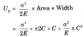
6. The elastic strain energy for unit volume is given by,
7. If the surface energy per unit area is γ then the surface energy for a crack of length 2C and unit width will be,
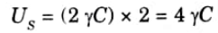
We multiply by 2 because there are two faces.
8. Applying Grifith’s criterion, the change in surface energy with fracture length must match the change in elastic strain energy for the crack to propagate.
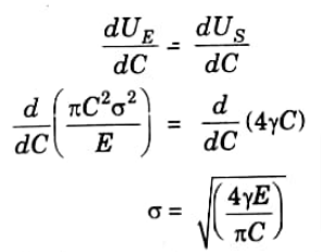
9. This finding demonstrates that the stress required to cause fracture increases inversely as the square root of the crack length, meaning that the tensile stress of a material that is entirely brittle will depend on the length of the longest crack the material currently has.
b. Discuss the fatigue failure and method of developing S-N curve for steel using RR Moore test.
Ans. A. Fatigue Failure:
- 1. Fatigue fracture happens when there are fatigue fractures, which are typically brought on by cyclic loads, at surface flaws such machine marks and slide steps.
- 2. Despite the fact that the initial stress concentration associated with these cracks is too low to result in brittle fracture, it may still be enough to induce the fissures to slowly expand into the interior. The fissures may eventually deepen to the point where the stress concentration exceeds the fracture strength, leading to dramatic failure.
- 3. The degree of crack propagation is determined by how brittle the material is that is being tested.
- 4.With brittle materials, the crack continues to develop until the remaining region can no longer support the load, at which point an abrupt virtually ductile fracture occurs. In contrast, with ductile materials, the crack continues to grow until the remaining area can no longer support the load.
- 5. Fatigue failures can be recognized by the appearance of fracture.
B. S-N Curve:
- 1. S-N curve represents the dependence of the life of the specimen, in number of cycles to failure N, on the maximum applied stress σ.
- 2. S-N curve is the basic method of presenting engineering fatigue data.
- 3. The rotating beam machine’s typical S-N curves are displayed in the (Fig.)
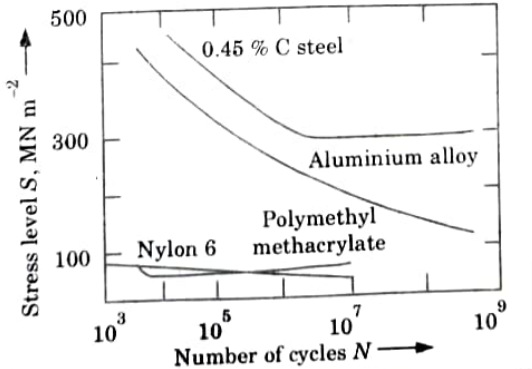
- 4. The number of stress cycles a metal can withstand before failing rises with decreasing stress, as shown in (Fig.).
- 5. Generally, N is taken as the number of cycles of stress to cause complete fracture of the specimen. Fatigue tests at low stresses are usually carried out for 107 cycles and sometimes to 5 x 10⁸ cycles for non-ferrous metals.
- 6. The S-N curve becomes horizontal for a select few significant engineering materials, including steel and titanium, at a specific limiting stress. The material is thought to be capable of withstanding an unlimited number of cycles before failing if the limiting stress, also known as the fatigue limit or endurance limit, is below it.
- 7. The S-N curve in the majority of non-ferrous metals, including aluminium, magnesium, and copper alloys, gradually slopes downward with more cycles. Because the S-N curve never crosses the horizontal plane, these materials lack a genuine fatigue limit.
- 8 The S-N curve is also known as the Wohler curve.
Important Long Questions in Materials Engineering
a. Draw and explain the iron carbon diagram and show all invariant reaction and phases in it.
Ans. A. Iron-carbon Equilibrium Diagram:
- 1. In (Fig.), Fe-C phase diagram is shown. Carbon is an interstitial impurity in iron and soluble in iron.
- 2. There are different types of solid phases of iron-carbon solid solution as:
- a. At room temperature, ferrite (a-iron) is stable and it has a BCC crystal structure.
- b. At temperature 912 °C, ferrite transforms to :austenite (γ-iron).
- c. Above the temperature 1394 °C, austenite transforms to a BCC crystal structure δ-phase. δ-phase has a melting point of 1538 °C.
- 3. Cementite (Fe3C) forms when solubility limit of carbon in a-ferrite is exceeded below 727 °C.
- 4. Fe3C also co-exists with the γ-phase in the region 727 °C to 1147 °C.
- 5. The cementite mineral is extremely dense and brittle. Cementite is not an equilibrium compound; it is just a metastable compound.
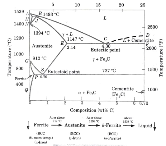
- 6. Eutectic point and eutectoid point of Fe-C equilibrium diagram are explained as following:
i. Eutectic Point:
- 1. Eutectic point is shown in the phase diagram indicated as point C.
- 2. At point C, Eutectic composition = 4.3 % carbon (percent by weight) Eutectic temperature =1147 °C 3. There is an equilibrium state between liquid state (L) and two solid phases (γ phase and cementite).
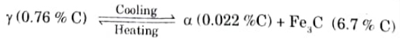
ii. Eutectoid Point:
- 1. Point S is indicated as eutectoid point.
- 2. At point S, there is an equilibrium state between solid state and two solid phases (a and cementite).
- 3 Eutectoid composition = 0.76 % carbon (percent by weight).
B. Feature of the Fe-C Diagram: The salient features of the equilibrium diagram (Fig.) are as follows:
- 1. The transformation that takes place in alloys with compositions ranging from pure iron to 6.67% carbon is discussed in the iron-carbon equilibrium diagram.
- 2. Point A is the highest melting point (1539°C) of pure iron and point Dis the melting point (approx. 1550 °C) of the iron carbide (Fe3C called cementite) having 6.67 % C.
- 3. Lines passing through points A, B, C, and D are liquidus lines, while lines passing through points A, H, J, E, C, and F are solidus lines. The constant temperature line E-C-F is where solidification occurs at its lowest temperature, 1130 °C.
- 4. The allotropic transformations at high temperature are depicted in the diagram’s upper left corner. At a temperature of 1493 °C, the peritectic transition shown by line HJB is occurring.
- 5. When the alloy crosses, the liquidus line A-B-C-D, solidification starts and completes along A-D-C-F. Austenite is precipitated along A-B–C and cementite along C-D.
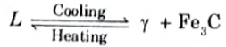
- 6. Austenite and cementite both precipitate concurrently from the liquid alloy at point C (1130 °C and 4.3% C), forming the eutectic cast iron known as ledeburite. This structure complies with eutectic transformational laws.
C. Significance:
- 1. The iron-carbon diagram reveals that the solubility of carbon in γ-iron is substantially greater in y-iron austenite than in a-iron ferrite, reaching a maximum value of little over 2 wt% at 1147 °C.
- 2. The ability to generate a supersaturated solid solution of carbon in iron is made possible by the high solubility of carbon in -iron during solution treatment in the -region and quick quenching to room temperature.
Long Questions in Materials Engineering – AKTU Btech
a. Explain surface hardening of steel. Discuss any two method of surface hardening with neat sketch.
Ans. 1. Another heat-treatment technique is surface hardening, which involves hardening a metal’s surface layers to a given depth while leaving the core relatively soft.
2. The surface’s chemical makeup is altered, which sets it apart from case hardening. Second, because the metal is heated and cooled quickly, the metal’s core is undamaged.
3. There are two methods of heat treatment in surface hardening:
a. Induction Hardening :
- 1. It is a method of surface hardening in which a copper inductor surrounding the surface being hardened is passed a high frequency current with a frequency of about 2000 cycles per second.
- 2. The inductor acts as a primary coil of a transformer.
- 3. As seen in, the work that needs to be toughened is put inside the inductor without touching it (Fig.)

- 4. There are several holes in the inductor block where water can be sprayed to quench it. Induced eddy currents and hysteresis loss at the work’s surface are what cause the heating effect.
- 5. The most common steels to be induction hardened are those with 0.35 to 0.55% carbon content. In order to increase the depth of current penetration, the hardening temperature is above the Curie point at 768 °C.
- 6.Water sprays directed from the inductor immediately cool the hot areas.
- 7. Many industrial operations employ induction hardening extensively, for example, on camshafts, gears, axles, etc.
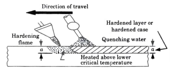
b. Flame Hardening:
- 1. This method relies on fast heating and quenching to give the work a hard surface and a soft core.
- 2. The work is heated above its critical temperature using an oxy-acetylene flame, and quenching is accomplished by a water spray directed at the surface.
- 3. The torch foThe method of heating the work might vary depending on whether it is stationary or moves gradually over the work, as shown in (Fig.).
- 4. This method is applied for hardening cast gears, mill rolls or worms.
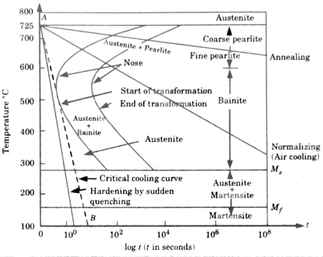
b. Explain the method of developing TTT curve. Draw the TTT diagram for eutectic steel and show transformation of austenite to pearlite, bainite and martensite.
Ans. A. TTT-Diagram:
- 1. Diagram of temperature, time, and transformation shows the relationship between the beginning and end of the production of various microstructures.
- 2. Its shape is same as the English alphabet ‘C’ so it is known as C-curve.
- 3. The nose of this curve indicates the least time taken for a particular transformation.
- 4. The critical cooling curve is the line that runs through the nose (or tangent at the nose of the C-curve), and the critical cooling rate is the slope of that line.
- 5. The conversion of austenite to pearlite is depicted in Fig. The beginning of austenite’s transition into pearlite may be seen in the leftmost C-curve.
- 6. This curve contains 100% austenite and 0% pearlite. The dashed curve then reflects the change of 50% of austenite into pearlite, while the rightmost C-curve depicts the transformation of 100% of austenite into pearlite.
- 7. Only for transformations when the alloy temperature is maintained constant throughout the course of the reactions are these curves reliable.

- 8. Thus these plots are also known as isothermal transformation diagrams or TTT diagrams.
- 9. Different microstructures, such as pearlite (coarse or fine), bainite, austenite + martensite, and martensite, can be produced depending on the cooling rate.
- 10. Line pearlite is produced via annealing when the cooling rate is slow.
- 11. In normalizing the cooling rate is high by which we get bainite structure.
- 12. A complete feature of TTT diagram to show its different phase is shown in (Fig.).
B. Importance of TTT Diagram:
- 1. It shows the structure that we obtained at different cooling rates.
- 2. It illustrates the cooling rate necessary for austenite to change into pearlite, bainite, or martensite.
- 3. It shows the time required for transformation to various phases.
Important Question in Material Engineering
a. Discuss the need of alloying of steel and also discuss the effect of different alloying element on properties of steel
Ans. A. Need of Alloying of Steel :
Purposes of alloying elements of steel are as follows:
- 1. To impart a fine grain size to steel.
- 2. To improve case hardening properties.
- 3. To improve elasticity.
- 4 To improve corrosion, fatigue resistance.
- 5. To improve hardness, toughness and tensile strength.
- 6. To improve machinability.
- 7. To improve high or low temperature stability.
- 8. To improve cutting ability.
- 9. To improve wear resistance.
- 10. To improve ductility.
B. Effect of Different Alloying Elements on Properties of Steel :
| S. No. | Alloying Elements | Effect on the Properties of Steel |
| 1. | Nickel | 1. Increases toughness. 2. Improve response to heat treatment especially in large sections. 3. In large amount provides special electrical and magnetic properties. 4. Improves forming properties of stainless steel. |
| 2. | Chromium | 1. Provides stainless property in steel. 2. Increase hardenability. 3. Increase high temperature strength. |
| 3. | Manganese | 1. Counteracts brittleness from sulphur.2. Increases strength and hardness markedly. 3. Lowers both ductility and malleability ifit is present in high percentage with high carbon content in steel. |
| 4. | Vanadium | 1. Improves response to heat treatment. 2. Provides control of structure. 3. Improves fatigue resistance |
| 5. | Tungsten | 1. Retention of hardness and toughness at high temperature. 2. Enhances the effects of other alloying elements. 3. Improves high temperature strength. |
| 6. | Silicon | 1. High electrical resistance and magnetic permeability. 2. Increases hardenability. 3. Improves toughness |
| 7. | Copper | 1. In small amount improves atmospheric corrosion resistance. 2. Act as a strengthening agent. |
b. Discuss the composition and application of following alloys (i)Monel Metal (ii) Muntz Metal (iii) Gun metal (iv) Duralumin (v) Y-alloy
Ans. i. Monel Metal :
- 1. It is a significant copper and nickel alloy. It is mostly composed of nickel (68%), copper (29%), and additional elements like iron, manganese, silicon, and carbon (3%).
- 2. When it comes to corrosion resistance, it outperforms bronze and brass.
- 3. Condenser tubes, steam turbine blades, propellers, and pump fittings are all made with it.
ii. Muntz Metal :
- 1. Consists Muntz metal, of 60 percent copper and 40 percent zinc.
- 2. It is utilized in hot forgings, heat exchanger and condenser tubing, condenser plates, and architectural panel sheets.
iii. Gun metal :
- 1. An alloy of copper, tin, and zinc is called gun metal. It’s sometimes referred to as admiralty gun metal.
- 2. The composition of gun metal is 88 % Cu + 10 % Sn +2% Zn.
- 3. A small quantity of zinc is added:
- i.. To clean the metal and
- ii. To increase its fluidity
- 4. Although forging may be done with ease at 600 °C, it is not ideal for work at low temperatures.
- 5. This is very strong resistant to corrosion by water and moist atmosphere. It has very good strength.
- 6. It is widely utilised for the casting of firearms, boiler fittings, bushes, bearings, and glands.
iv. Duralumin :
- 1. It is sometimes referred to as an aluminium wrought alloy. Its tensile strength can be increased to 400 MPa with heat treatment and case hardening.
- 2. It contains 3.5 % Cu, 0.5 % Mn, 0.5 % Mg and 95.5 % Al.
Uses:
- 1. Due to its ability to withstand a working temperature of up to 500°C, it is mostly utilised for forgings, stampings, sheets, tubes, and rivets.
- 2. It is mostly employed in the manufacture of aviation and vehicle parts due to its high strength and low weight.
- 3. lt is also used for manufacturing of connecting rods, bars, rivets and pulleys etc.
v. Y-alloy:
- 1. It is a copper-aluminum alloy. Its strength and machinability are improved by copper.
- 2. Additionally, Y-alloy contains very trace amounts of Si, Mg, and Fe, up to 0.6 h each. Duralumin is less strong than Y alloys at high temperatures.
Uses:
- 1. It is mostly used for casting but it may also be used in forged components.
- 2. It is employed in the production of aviation engine cylinder heads and pistons because of its superior strength at high temperatures.

Materials Engineering Quantum, Syllabus, Important Questions
| Label | Link |
|---|---|
| Subject Syllabus | Syllabus |
| Short Questions | Short-question |
| Important Unit-1 | Unit-1 |
| Important Unit-2 | Unit-2 |
| Important Unit-3 | Unit-3 |
| Important Unit-4 | Unit-4 |
| Important Unit-5 | Unit-5 |
| Question paper – 2021-22 | 2021-22 |
Materials Engineering Quantum PDF: | AKTU Quantum PDF:
| Quantum Series | Links |
| Quantum -2022-23 | 2022-23 |
AKTU Important Links | Btech Syllabus
| Link Name | Links |
|---|---|
| Btech AKTU Circulars | Links |
| Btech AKTU Syllabus | Links |
| Btech AKTU Student Dashboard | Student Dashboard |
| AKTU RESULT (One VIew) | Student Result |