
In this Blog or Article we are focus on Materials Engineering’s Important Question with Answer. This is Unit 02 Static Failure Theories. Hope this session will help you in your AKTU Btech Exams.
Q1. What is meant by fracture ? Explain the characteristics of brittle fracture and ductile fracture.
Ans. A. Fracture:
- 1. Fracture is the term used to describe a material’s failure under load when it splits into two or more pieces. All service conditions can lead to fracture.
- 2. Fatigue causes materials that are subjected to alternating or cyclic loading to fail. In these situations, the fracture is known as a fatigue fracture.
- 3. Creep fracture can cause materials used at high temperatures to fail.
- 4. Any fracture involves two steps :
- i. Crack formation, and
- ii. Crack propagation.
- 5. The mode of fracture (ductile or brittle fracture) depends on the mechanism of crack propagation.
B. Ductile Fracture: Ductile fractures have the following characteristics :
- 1. The area of the ductile fracture has undergone significant plastic deformation.
- 2. Ductile fractures are ones that can only happen when the shear stress is greater than the shear strength. As a result, the micro-mechanics of fracture are in shear.
- 3. Unlike brittle fracture, the surface of a ductile fracture is not always correlated with the direction of the primary tensile stress.
- 4. Dull and fibrous surface characteristics of a ductile fracture can be seen. Deformation on the fracture surface is the root of this.
- 5. Ductile fractures proceed only as long as the material is being strained.
- 6. In addition, brittle cracks cannot be stopped once they start spreading through a material.
C. Brittle Fracture : Following are the characteristics of brittle fracture :
- 1. It occurs suddenly without any warning.
- 2. It occurs with little or no plastic deformations.
- 3. The rate of propagation of the crack is very fast.
- 4. The fractured surface is shiny and flat.
- 5. It occurs along the cleavage planes.
Q2. Explain brittle and ductile fracture with the help of graph.
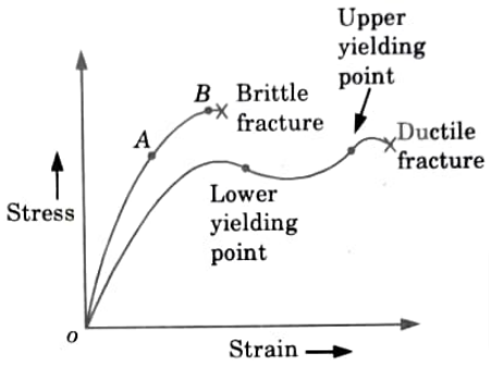
Ans. 1. (Fig.) shows the stress-strain diagram for the ductile and brittle fracture of material.
2. From O to A, a proportionate limit is observed, meaning that if tension is released, the material will return to its initial position.
3. If more force is applied at point B, the yield point is attained, and the brittle fracture takes place at this point.
4. On additional application of the strained, ductile materials attained an upper yielding point due to their stronger elastic properties.
5. The material fractures, resulting in ductile fracture, if stress is raised over the higher yielding point.
Q3. What is Mohr-Coulomb failure theory?
Ans. 1. Shear stress as well as normal stress are both factors in the Mohr-Coulomb theory, a mathematical model that describes how brittle materials like concrete or rubble piles react.
2. This idea typically applies to substances whose compressive strength is significantly higher than their tensile strength.
3. In concrete and other comparable materials, it is used to calculate the failure force and the angle of fracture of a displacement fracture.
4. It can be demonstrated that when a material fails in accordance with Coulomb’s friction theory, the displacement introduced at failure will form an angle with the line of fracture that is equal to the angle of friction.
5. This enables the determination of the material’s strength by contrasting the internal mechanical work created by strain and stress at the line of failure with the exterior mechanical effort supplied by displacement and external load.
6. Because of energy conservation, the sum of these must be zero, allowing us to compute the construction’s failure load.
7. Coulomb assumed the relation between t, and o to be linear and gave the following equation popularly known as Coulomb’s equation.

Where, c is the intercept on the strength envelope on the t-axis and tan ф is the slope of the strength envelope, c is known as cohesion and ф is angle of internal friction or more comprehensively angle of shearing resistance.
Q4. Discuss the stress intensity factor approach.
Ans. 1. The stress intensity factor (K) is used in the field of fracture mechanics.
2. The magnitude ofK depends on :
i. Sample geometry,
ii. Size and location of the crack,
iii Magnitude of load, and
iv. Distribution of load.
3. The crack tip stress field is characterised by a single parameter known as the stress intensity factor.
4. The stress intensity factor establishes failure criteria owing to fracture and describes the stress condition at a crack tip in relation to the rate of crack propagation.
5. It is a technique to figure out how much energy is available for fracture in terms of the asymptotic stress and displacement fields surrounding a crack front in a linear elastic solid.
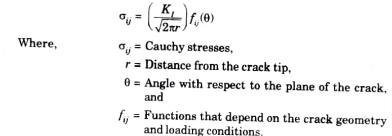
6. This asymptotic expression for the stress field in loading is related to the stress intensity factor as given below,
Q5. What is a fatigue failure ? How is a fatigue test carried out ?
Ans. A. Fatigue Fracture:
- 1. The presence of fatigue cracks, typically caused by cyclic pressures, at surface flaws such machine marks and slip steps leads to fatigue fracture.
- 2. Despite the fact that the initial stress concentration associated with these cracks is too low to result in brittle fracture, it may still be enough to induce the cracks to slowly expand into the interior. The fissures may eventually deepen to the point where the stress concentration exceeds the fracture strength, leading to dramatic failure.
- 3. The degree of crack propagation is influenced by how brittle the material is that is being tested.
- 4. With ductile materials, the crack continues to grow until the remaining area can no longer hold the load and an abrupt virtually ductile fracture occurs. In brittle materials, the crack grows to a critical size from which it quickly spreads right through the structure.
- 5. Fatigue failures can be recognized by the appearance of fracture.
B. Fatigue Tests:
- 1. To ascertain a material’s ability to sustain repeatedly applied loads, fatigue tests are carried out in the lab.
- 2. Testing for fatigue It is crucial to identify the different fatigue properties of materials depending on the type of load and how it is applied.
- 3. The basic types of loading are simple axial loading, bending, torsion, and a combination of these three.
- 4. Fig.shows a constant load machine used for fatigue testing.
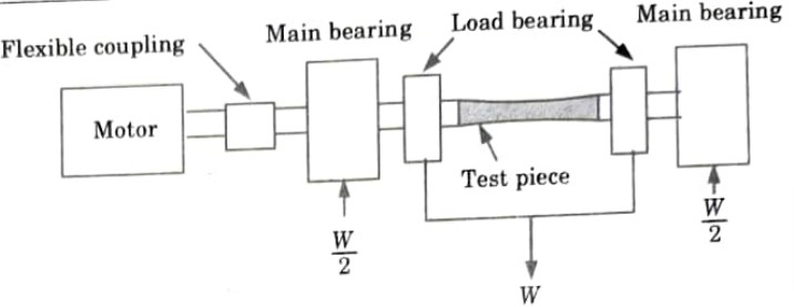
- 5. The test specimen is inserted into the apparatus in the shape of a cantilever, which extends a shaft. A motor powered by electricity turns the shaft.
- 6. Ball bearings are used to apply a dead load to the machine. The specimen is subjected to a significant bending moment, which the bearing releases from the motor.
- 7. Any given location on the specimen’s surface alternates between a condition of maximum tensile stress and a state of greatest compressive stress while it is rotating.
- 8. There is sinusoidal variation of stress as the specimen rotates.
- 9. The stress is greatest at the surface and zero at the centre.
- 10. Fatigue may set in depending on the number of cycles and the amount of applied force. Where the stress value is large, there will be fewer cycles.
- 11. On the other hand, if there is less applied tension, it will be necessary to increase the number of cycles. A stress is eventually achieved below which failure is not possible within the parameters of the usual test. The endurance limit is referred to as this stress value.
- 12. It is presumed that fracture won’t occur if it doesn’t happen within the number of cycles provided for the material.
Q6. What is non destructive testing (NDT) ? Explain in detail any two NDT methods.
Ans. A. NDT:
- 1. It alludes to a technique for examining engineering materials without damaging them to find internal defects.
- 2. Another definition is “the use of non-invasive technology to assess the structural or material integrity of an object or to quantitatively measure some of its properties.”
B. NDT Methods:
a. Penetrant Testing:
- 1. The test specimen is covered with fluorescent dye solution in this approach. Developers are then applied after the surplus penetrant has been carefully removed.
- 2. These developers serve as blotters, pulling the trapped penetrant from the defect to the open surface.
- 3. The colour difference between the penetrant and developer created by the fluorescent dyes makes these penetrants much easier to see presently.
- 4. Ultraviolet lights are used which make the bleed out penetrant readily seen.
b. Magnetic Particle Testing:
- 1. Any magnetizing technology that produces a magnetic field may be used in this method. The surface being examined is then covered with magnetic ink, a powdered or liquid magnet.
- 2. A surface or near-surface defect cuts the magnetic flux line at the defect location, creating a new magnetic pole. This concentrates the iron particles near the flaw or imperfection, making it easy to see the flaw.

Materials Engineering Quantum, Syllabus, Important Questions
| Label | Link |
|---|---|
| Subject Syllabus | Syllabus |
| Short Questions | Short-question |
| Important Unit-1 | Unit-1 |
| Important Unit-2 | Unit-2 |
| Important Unit-3 | Unit-3 |
| Important Unit-4 | Unit-4 |
| Important Unit-5 | Unit-5 |
| Question paper – 2021-22 | 2021-22 |
Materials Engineering Quantum PDF: | AKTU Quantum PDF:
| Quantum Series | Links |
| Quantum -2022-23 | 2022-23 |
AKTU Important Links | Btech Syllabus
| Link Name | Links |
|---|---|
| Btech AKTU Circulars | Links |
| Btech AKTU Syllabus | Links |
| Btech AKTU Student Dashboard | Student Dashboard |
| AKTU RESULT (One VIew) | Student Result |