
Irrigation and Water Resource Engineering: AKTU question paper with answers supplies B.Tech students with crucial practice material for irrigation and water resource engineering examinations by presenting a diverse range of exam-style questions and comprehensive solutions.
Dudes 🤔.. You want more useful details regarding this subject. Please keep in mind this as well.

Important Questions For Irrigation and Water Resource Engineering:
*Quantum          *B.tech-Syllabus
*Circulars           *B.tech AKTU RESULT
* Btech 4th Year
Section A: Short Important Questions of Irrigation and Water Resource Engineering
a. Describe Probable Maximum Precipitation (PMP).
Ans.
- 1. The precipitation resulting from the most essential climatic combinations that are thought likely of occurring is known as the probable maximum precipitation (PMP) for a region.
- 2. It is the rainfall over a basin that would create the flood flow with almost no probability of being exceeded.
b. Define water budget equation.
Ans. The continuity equation stated in terms of several stages of the hydrological cycle is known as the water budget equation or the hydrological budget equation for surface flow.
For a given catchment in a time ∆t,
Inflow – Outflow = Storage (Continuity equation).
c. What is the assumption made in unit hydrograph ?
Ans. Following are the assumptions made for unit hydrograph theory :
- i. The surplus rainfall has a constant intensity (WD cm/hr) across the effective storm duration of D hours.
- ii. The extra rainfall is evenly spread throughout the catchment basin.
- iii. The duration of the direct runoff caused by an excess rainfall of a particular period is constant.
d. Define trickle irrigation system.
Ans.
- i. Irrigation water is delivered on the surface in 12 to 16 mm diameter tubing fed by big feeder pipes in this approach.
- ii. Water is permitted to drop or trickle slowly through the nozzle or oritices at almost no pressure. The soil at the root zone of crops is thus kept moist at all times.
- iii. With this strategy, crops can also be grown successfully on saline lands. This strategy has proven to be quite useful in reclaiming and developing desert and arid areas.
- iv. The biggest disadvantage of this approach is its high cost.
e. Explain Lacey’s silt factor.
Ans. Silt factor is connected to the average particle size. It is given by,
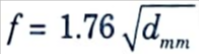
where, dmm = Average particle size in mm
f. Define canal regulation works.
Ans. The works that are built to govern and regulate canal discharges, depths, velocities, etc. are referred to as canal regulation works.
g. Define silting and scouring in canals.
Ans. Scouring: Scouring occurs as a result of surface flow of water, particularly at high velocity or during significant flood discharge. It erodes the soil and takes it downstream with the passage of water.
Silting: After the scouring phenomena, the eroded material or soil settles at the bottom of the river. This is known as silting, or particle settling at the bed.
h. Define the objectives of diversion headwork.
Ans. A diversion headwork serves to raise the water level in the river and divert the required quantity into the canal.
i. Explain specific capacity of well.
Ans. The specific capacity of a well is the measure of the effectiveness of the well, and is defined as the yield of the well per unit drawdown.
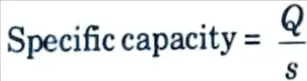
where, s = drawdown.
Q = well discharge or the yield.
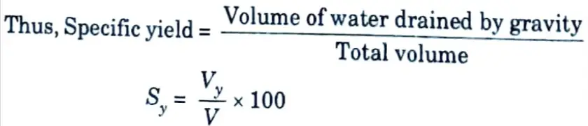
j. Define specific yield.
Ans. The specific yield of an aquifer is defined as the ratio expressed as a percentage of the volume of water which after being saturated, can be drained by gravity to its own volume.
Section B : Briefly Explained Questions of Irrigation and Water Resource Engineering
a. Write a short note on synthetic unit hydrograph. How will you derive the synthetic unit hydrograph from a number of unit hydrograph ? Illustrate the method with suitable example in a tabular form.
Ans. A. Synthetic Unit Hydrograph :
- 1. We have shown that unit hydrographs can be generated if rainfall and runoff records are available.
- 2. Unfortunately, these statistics are not available for ungauged rivers. In some other circumstances, the available data may be limited.
- 3. Unit hydrographs are derived for such catchments by matching the selected basin features to the unit hydrograph shape.
- 4. A synthetic unit hydrograph is the resulting hydrograph created from basin characteristics relationshp.
B. Snyder’s Method :
- 1. Snyder investigated data from Appalachian Highlands catchments in the eastern United States before developing empirical equations for synthetic hydrographs.
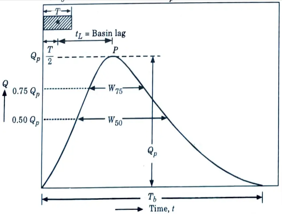
- 2. Snyder selected three parameters of unit hydrograph :
- i. Base width, Tb
- ii. Peak discharge, Qp
- iii. Basin lag, tL.
3. The equations given by him take into account catchment area, shape of basin, topography, channel slopes, stream density and channel storage.
4. He eliminated all these parameters except the first two, by including them in a single co-efficient Ct.
5. He dealt with the size and shape of the catchment by measuring the length of the main stream channel, by proposing the following equation for basin lag:
tL = Ct (Lca x L)0.3 …..(2.15.1)
where, tL = Basin lag in hours, (basin lag is the time between mass of centre of unit rainfall of T hour duration and runoff peak flow)
Ct = A co-efficient depending upon units and drainage basin characteristics (1.35- 1.65).
L = Distance from station to cat chment boundary measured along the main stream, in km.
Lca = Distance along the main stream from gauging station to a point opposite the centroid of the watershed, in km. 6. The peak discharge of Qp unit hydrograph of standard duration T is given by,
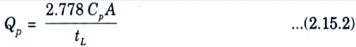
where, Qp = Peak discharge (m3/sec).
Å = Catchment area (km2).
Cp = A regional constant, ranging from 0.56 to 0.69.
7. Snyder adopted the standard duration (T) hours of effective rainfall given by,
T = (2/11)tL …(2.15.3)
8. The duration of surface runoff or the base length Tb of unit hydrograph is given by,
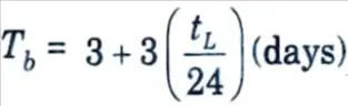
When Tb is expressed in hours,
Tb = 72 + 3 tL ….(2.15.4)
(where both Tb and tL are in hours)
9. It is found that equation (2.15.4) gives unreasonably long base periods for small catchments. Some investigators recommend that a base period equal to five times the time to peak should be taken :
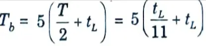
or Tb = 5.455 tL ….(2.15.5)
Alternatively, assuming a triangular shape of unit hydrograph,
Tb = 5.556/qp
10. Sketching of unit hydrographs becomes easier by adopting the following recommendations given by US Army Corps of Engineers, for widths of unit hydrographs at 50 and 75 % of the peak discharge :
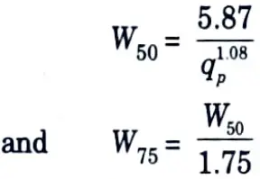
where, W50 = Width of unit hydrograph in hours, at 50 % peak discharge.
W75 = Width of unit hydrograph, in hors, at 75 % peak discharge.
qp = Qp/A= Peak discharge per unit area.
11. Usually, one thírd of this width is kept before the unit hydrograph peak and two thirds after the peak.
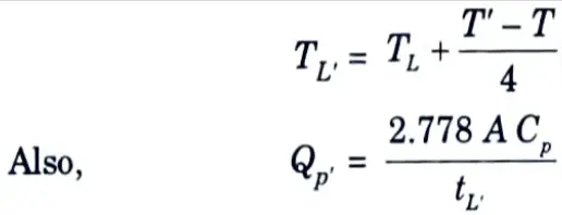
12. If synthetic unit hydrograph of any other duration T’ is required, then the modified basin lag is
Example :
A set of information extracted for estimating SUH are given below :
Area, A = 606.52 km2
Length of longest flow path, L = 56.4 km
Centroidal flow path, Lc = 28.2 km
Answer :
1. 1 hr Synthetic UH parameters generated by 1 cm effective rainfall. SUH parameters are computed by using equations as follows :
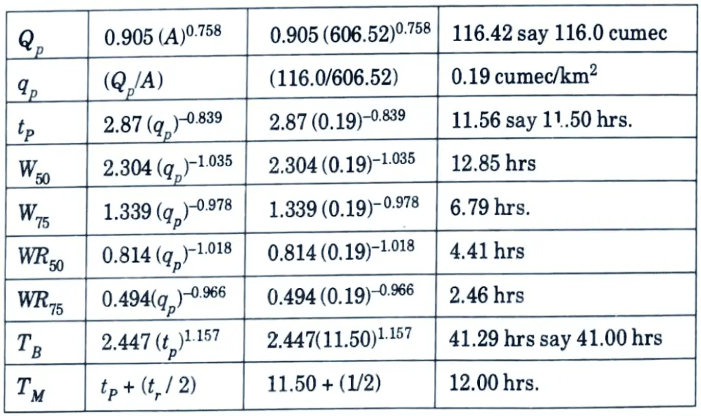
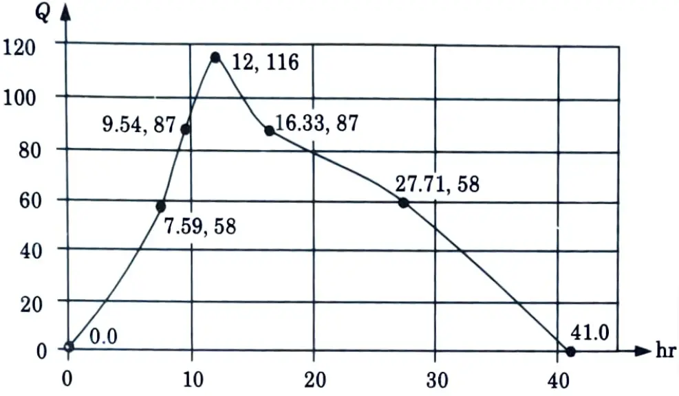
2. An SUH based on the estimated parameters in table is shown in Fig.
b. Define following terms:
i. Depth area duration curve.
ii. Probable maximum precipitation.
iii. Evapotranspiration.
iv. 𝚽 – index.
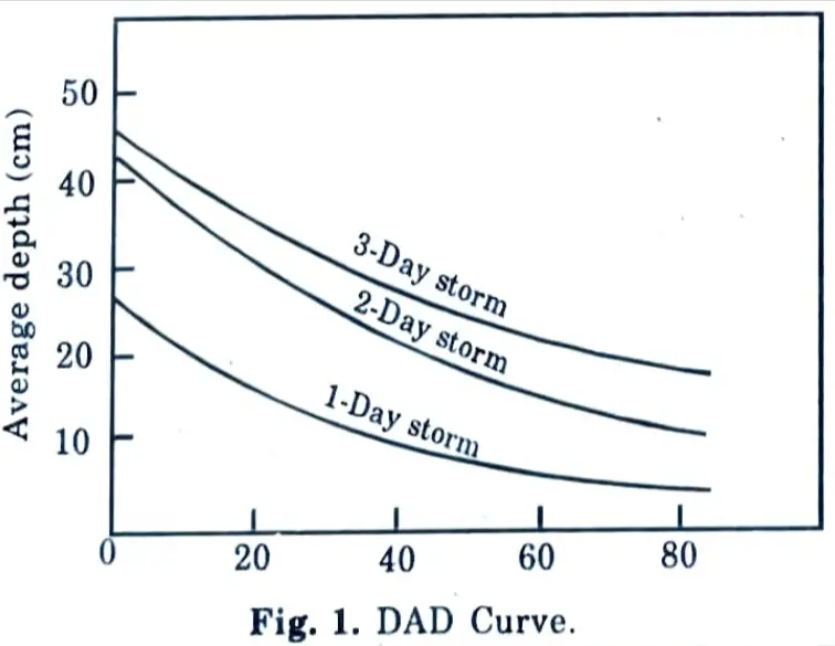
Ans. i. Depth Area Duration Curves :
- 1. Rainfall rarely falls consistently across the watershed.
- 2. Storms overall depth of rainfall and intensity vary from the centre to the periphery.
- 3. Understanding the maximum depth of rainfall occuring on various sized areas during storms of varying durations is critical in many hydrological design problems.
- 4. DAD analysis is the development of a link between maximum depth, area, and duration for a region. The average depth (cm)
- 5. DAD analysis is used to determine the maximum amounts of precipitation for different durations over different sized areas.
ii. Probable maximum precipitation :
- 1. The precipitation resulting from the most essential climatic combinations that are thought likely of occurring is known as the probable maximum precipitation (PMP) for a region.
- 2. It is the rainfall over a basin that would create the flood flow with almost no probability of being exceeded.
- 3. From the statistical studies, PMP can also be estimated from the following equation :


σ = Standard deviation of the series.
K = Frequency factor, which is usually in the neighbourhood of 15.
iii. Evapotranspiration: It is the sum of the water lost to the atmosphere by the plants through transpiration, and the water evaporated from the soil or water or water body, surrounding the plant.
iv. 𝚽 – index :
- 1. The 𝚽 – index is the average rainfall above which the rainfall volume is equal to the runoff volume.
- 2. The 𝚽 – index is derived from the rainfall hyetograph with the knowledge of the resulting runoff volume.
- 3. The initial loss is also considered as infiltration.
- 4. The 𝚽 – value is found by treating it as a constant infiltration capacity.
c. What is the problem of water logging ? What are the poor effects of water logging ? Describe some suitable remedial measures against water logging in brief.
Ans. Water Logging :
- i. Waterlogging occurs when an agricultural land’s productivity or fertility is hampered by a high water table.
- ii. The depth of the water table at which it tends to clog the soil and be damaging to plant development and substance is determined by the height of the capillary fringe, which is the height to which water will rise due to capillary action.
- iii. The height of the capillary fringe increases with fine-grained soil and decreases with coarse-grained soil.
- iv. The normal height of the capillary fringe encountered in agricultural soils is between 0.50 and 1.60 m.
Effects of Water Logging: Following are the effects of water logging :
- 1. Inhibiting Activity of Soil Bacteria :
- i. Plant food liberation is dependent on the action of soil bacteria, which requires a suitable amount of oxygen in the air to function properly.
- ii. Waterlogging occurs when the soil pores inside the root zones of commonly grown crops get so saturated that they effectively cut off the usual passage of air.
- 2. Decrease in Available Capillary Water :
- i. Plant life derives its substance from the soil-solution that surrounds soil particles and is absorbed into the plants via capillary action and osmosis.
- ii. When the water table is high, plant roots are confined to the upper layers of soil above the water table, whereas when the water table is low, plant roots have more room to flourish.
- 3. Fall in Soil Temperature: A waterlogged soil warms up slowly and due to lower temperature, action of soil bacteria is sluggish and plant food available is less.
- 4. Defective Air Circulation: When the water table is high, drainage is impossible, and the carbon dioxide emitted by plant roots cannot be dissolved and removed. As a result, fresh air with oxygen is not pulled in, and the activity of soil microbes and plant growth declines.
- 5. Rise of Salt :
- i. The accumulation of alkali salts in the surface soil caused by the upward flow of water established in waterlogged fields is also caused by the rising of the water table.
- ii. If the underlying layers contain alkali salts in solution, water is pulled up and evaporates, leaving the salt on the surface.
- 6. Delay in Cultivation Operations :
- i. In flooded areas, cultivation procedures like ploughing and mulching are either impossible or laborious, and are always postponed.
- ii. Crop sowing and growth are also delayed.
- iii. Crop output is low, and it arrives late in the market, causing producers to lose money.
- 7. Growth of Wild Flora: Naturally occurring vegetation, like water hyacinth, flourishes in flooded soils. Hence, agricultural yield is decreased. For clearing it out, a cultivator must spend time and money.
- 8. Adverse Effect on Community Health: A soggy area’s climate becomes wet. The formation of stagnant pools may serve as a breeding ground for mosquitoes. As a result, the climate becomes exceedingly harmful to the health of the community.
Remedial Measures: Following are the various methods adopted as anti-water logging :
- 1. Lining of Canals and Water Courses: Attempts should be made to reduce the seepage of water from the canals and water courses. This can be achieved by lining them.
- 2. Reducing the Intensity of Irrigation: In areas where there is a possibility of water logging, intensity of irrigation should be reduced.
- 3. By Improving the Natural Drainage of the Area: Water should not be left standing for an extended amount of time to reduce percolation. By removing barriers from the line of natural flow, some direction alleviation can be gained.
- 4. By Adopting Consumptive Use of Surface and Subsurface Water: The introduction of lift irrigation to utilize ground water helps in lowering the water table in a canal irrigated area, where water-table tends to go up.
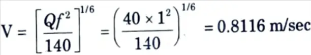
d. Using Lacey’s theory, design a trapezoidal irrigation channel (side slope, 1H:2V) carrying discharge of 40 m3/sec. Take silt factor as 1.0.
Ans. Given: Discharge Q = 40 m³sec, Silt factor, f = 1.0, Side slope =1H : 2V
To Find: Design a trapezoidal irrigation channel.
1. Velocity in the channel,
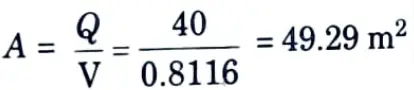
2. Area of the channel section,
3. Hydraulic mean radius is given by,
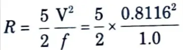
R = 1.647 m
4. Hydraulic mean radius for trapezoidal section is given by,
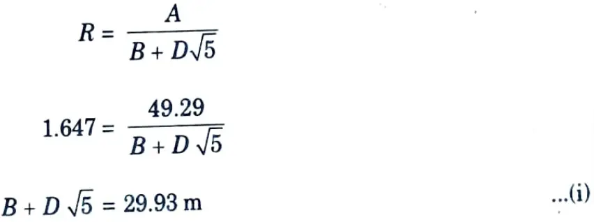
5. Area is given by,
A = BD + 0.5 D2
49.29 = BD + 0.5 D2 …(ii)
6. Solving the eg. (i) and eq. (ii), we get
Depth, D = 1.844 m
Width, B = 25.806 m
e. Write short notes on:
i. Well shrouding and well development.
ii. Types of open wells.
ii. Infiltration galleries.
iv. Hydraulic conductivity.
Ans. i. Well Shrouding :
- 1. Well shrouding is the technique of inserting coarse material such as gravel and coarse sand between the well-pipe (strainer pipe) and the aquifer soil to prevent finer soil particles from clogging the strainer.
- 2. This is critical in sandy and unconsolidated aquifer formations.
- 3. This is also necessary in slotted tube wells without a strainer.
- 4. A gravel-packed well is another name for a tube well.
Well Development: It is the process of removing finer particles from surrounding the screen in order to increase the permeability of the formation, which allows water to migrate towards the well.
ii. Types of open wells :
- 1. Kachha Well :
- a. A kachha well is a shallow-depth temporary well. It is only suitable for hard formations with vertical walls.
- b. They are only appropriate when the water table is quite close to the ground surface. Such wells frequently collapse after a period of time and are unsafe.
- 2. Well with Impervious or Pucca Lining :
- a. This is the most common type of open well, and is suitable for all types of formations.
- b. Once constructed, it becomes a permanent source of water supply.
- 3. Well with Pervious Lining :
- a. Such wells are appropriate for coarse formations. The lining is made of dry bricks or stones that are not mortared or bound together. As a result, water enters from the sides, and the flow is radial. These wells are usually plugged at the bottom.
- b. If there is no plug at the bottom the flow isa combination of radial and spherical pattern.
iii. Infiltration galleries :
- 1. They are horizontal or almost horizontal tunnels built at shallow depths (3 to 5 metres) along the river’s bank through water-bearing layers. These are also known as horizontal wells.
- 2. These galleries are often built with masonry walls and roof slabs, and they get their water from the aquifer via various porous drain pipes.
- 3. These pipes are typically coated with gravel to prevent fine sand particles from entering the pipe.
- 4. These tunnels or galleries are typically built on a slope, and the water collected in them is pumped to a sump well, where it is treated and given to consumers.
iv. Hydraulic Conductivity: It is described as a porous medium’s ability to transfer water under saturated or substantially saturated conditions.
Section 3 : Rate of Infiltration in Irrigation & Water Resource Engineering
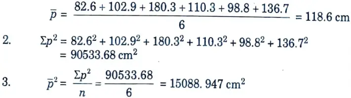
a. A catchment has six rain gauge stations. In a year, the 2. 3. annual rainfall recorded by
| Station | A | B | C | D | E | F |
| Rainfall (cm) | 82.6 | 102.9 | 180.3 | 110.3 | 98.8 | 136.7 |
Calculate the optimum number of rain gauge stations in the catchment for 10% error.
Ans. Given: Number of station, N = 6, Allowable percentage error, ε = 10 %
To Find: Optimum number of rain gauge.
1. Mean annual rainfall,
4. Standard deviation,
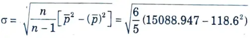
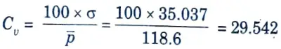
σ = 35.037 cm
5. Coefficient of variation,
6. Standard error in the estimation of the mean,
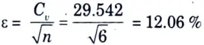
7. The error is limited to 10 %, so ε = 10 and the optimum number of rain gauges in the catchment is given by,
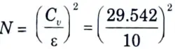
= 8.73 ≃ 9
Hence, optimum number of rain gauges is 9
b. Define infiltration and describe the factors that affect the process of infiltration. How will you measure the rate of infiltration?
Ans. Infiltration: It may be defined as the downward movement of water from soil surface into the soil mass through the pores of the soil.
Factors: Following are various factors, both meteorological as well as the characteristics of soil media, on which infiltration rate and infiltration capacity depends :
- 1. Condition of Entry Surface: (Vegetation covers versus bare land) :
- i. Infiltration capacity will be greater if the region is covered by grass, vegetation, and bushy plants.
- ii. On the other hand, if the soil surface is bare, the impact of rain droplets falling on the surface will promote in-washing of finer soil particles and clogging of the surface, resulting in a delay in infiltration.
- 2. Antecedent Moisture Conditions in Soil: Infiltration rate will depend on initial moisture conditions of soil. When the soil moisture is high, the infiltration rate (ft) will be low.
- 3. Temperature: Infiltration will be greater in the summer due to less viscous water than in the winter. Crystallisation of water in the pores limits the route under subzero temperatures, limiting or even stopping infiltration.
- 4. Intensity and Duration of Rainfall: Rainfall with a lower intensity results in a higher rate of infiltration. Rainfall of a longer length will result in less infiltration than the same amount of rain occurring as a series of discrete storms.
- 5. Movement of Man and Animals: When people and/or animals walk around a lot, the soil compacts, which reduces the infiltration rate.
- 6. Change Due to Human Activities: The cultivation of barren ground by producing crops and grass cover increases the rate of penetration. On the other hand, the construction of roads, residences, factories, and play areas, as well as overgrazing of pastures, reduces infiltration capacity.
- 7. Quality of Water: Silts and other impurities present in incoming water result in retardation of infiltration rate due to clogging of soil pores.
- 8. Presence of Ground Water Table: Presence of ground water table reduces infiltration. For infiltration to continue, the position of ground water table should not be very close.
- 9. Size and Characteristics of Soil Particles: If the soil has swelling minerals like illite and montmorillonite, the infiltration rate will reduce drastically.
Measures Infiltration Rate :
Horton’s Equation: Horton gave the following equation for finding infiltration rate (ft) at any time period (t)
ft = fc + (f0 – fc)e-kt
where, ft = Infiltration rate at any time t.
fc = Constant infiltration rate at time t = T(say)
f0 = Infiltration rate in the beginning (t = 0).
k = A constant which depends on the soil and vegetation.
Section 4 : Irrigation System in Irrigation & Water Resource Engineering
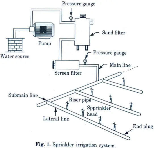
a. Describe the various method of irrigation system. Define sprinkler irrigation system with neat sketch.
Ans. Method of Irrigation System :
- 1. Surface Irrigation :
- i. Water is either ponded on the soil or allowed to flow continuously over the soil surface throughout the period of irrigation in all surface irrigation methods.
- ii. Using syphons, gated pipe, or turnout structures, irrigation water is injected into level or graded furrows or basins and permitted to advance across the field.
- iii. Surface irrigation is best suited to flat land slopes and medium to fine grained soil types that promote lateral water flow down the furrow row or over the basin.
- 2. Subsurface Irrigation :
- i. Subsurface irrigation (or simply sub irrigation) is the practice of applying water to soils directly under the surface.
- ii. Moisture reaches the plant roots through capillary action.
- iii. The conditions which favor sub irrigation are as follows :
- a. Impervious subsoil at a depth of 2 metres or more.
- b. A very permeable sub-soil.
- c. A permeable loam or sandy loam surface soil.
- d. Uniform topographic conditions, and moderate ground slopes.
- iv. When soil conditions are favourable for the development of cash crops (i.e., high-priced crops) on tiny areas, a pipe distribution system is sometimes installed down below the surface of the soil. Artificial sub irrigation is a way of applying water.
- 3. Sprinkler Irrigation :
- i. An attempt is made in this method to replicate natural rainfall. Irrigation water is applied to the land as a spray. Sprinkler irrigation is another name for this approach.
- Sprinklers can be used on any soil type and on any terrain.
- iii. Sprinkler methods can be fixed or movable, depending on the equipment and procedure used.
- 4. Trickle Irrigation :
- i. Irrigation water is delivered on the surface in 12 to 16 mm diameter tubing fed by big feeder pipes in this approach.
- ii. Water is permitted to drop or trickle slowly through the nozzle or oritices at almost no pressure. The soil at the root zone of crops is thus kept moist at all times.
- iii. With this strategy, crops can also be grown successfully on saline lands. This strategy has proven to be quite useful in reclaiming and developing desert and arid areas.
- iv. The biggest disadvantage of this approach is its high cost.
Sketch :
b. What is meant by crop rotation ? What are the advantages of crop rotation? Describe in brief with suitable examples.
Ans. Crops Rotation :
- 1. Crop rotation is the methodical planting of several crops in a specific order over a period of several years in the same growing space. This procedure aids in the preservation of soil nutrients, the reduction of soil erosion, and the prevention of plant diseases and pests.
- 2. There is no universally approved rotation schedule because the types of plants grown in a certain farm or garden are determined by the soil, climate, and resources available.
Objectives: Following are the objective of crop rotation :
- 1. Improve soil fertility and physical, chemical, and biological qualities by adding organic matter.
- 2. Using various agricultural and agronomical/cultural manipulations, keep the land free of disease, pests, and weeds.
- 3. Maintain a steady supply of food, feed, fodder, fibre, and fuel, as well as finances for different family obligations.
- 4. Selective cropping makes the optimum use of remaining soil moisture and nutrients.
- 5. Achieve greater insurance against natural calamities and instability in market prices.
- 6. Achieve higher yield without incurring extra expenditure.
Advantages: Following are the advantages of crop rotation :
- 1. Higher yield without incurring extra investment.
- 2. Enhanced soil fertility and microbial activities.
- 3. Avoid accumulation of toxic substances
- 4. Better utilization of nutrients and soil moisture.
- 5. Insurance against natural devastation.
- 6. Maintain soil health by avoiding insect pest diseases and weed problems.
- 7. Provide proper labour, power and capital distribution throughout the year.
- 8. Higher chances to provide diversified commodities.
Example: Following rotation of the crops give good results :
- i. Wheat great millet gram
- ii. Rice gram
- iii. Cotton wheat gram
- iv. Cotton wheat sugarcane
- v. Cotton great millet gram
Section 5 : Regime Channel in Irrigation & Water Resource Engineering
a. Water course has a culturable commanded area of 1200 hectares. The intensity of irrigation for crop A is 40 % and for B is 35 % both the crops being Rabi crops. Crop A has a kor period of 20 days and crop B has kor period of 15 days. Calculate the discharge of the water course if the kor depth for crop A is 10 cm and for B is 16 cm.
Ans. Given: Culturable commanded area = 1200 ha
Intensity of irrigation: For crop A = 40 % and for crop B =35 %
Kor period, B : For cropA = 20 days and For cropB= 15 day
Kor depth, ∆ : For crop A = 10 cm and crop B = 16 cm
To Find: Discharge of water.
1. For Crop A :
i. Area under irrigation = 1200 x 0.40 = 480 hectares
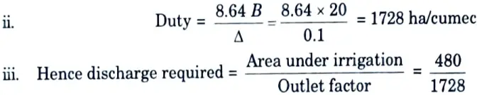
= 0.278 m3/sec
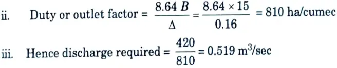
2. For Crop B :
i. Kor depth, ∆ = 16 cm = 0.16 m
Area under irrigation = 1200 x 0.35 = 420 hectares
3. Thus, the design discharge of water course
= 0.278 +0.519 = 0.797 ≅ 0.8 m3/sec
b. What do you understand by regime channel ? Explain the initial regime and final regime of a channel in Lacey’s theory.
Ans. Regime Channel: Lacey defined a regime channel as a stable channel that transports a solid charge. If a channel flows in infinite incoherent alluvium of the same nature as that transported and the silt grade and silt charge are all constant, it is in regime.
Initial and Final Regime Channel :
- Initial Regime: Even when only the bed slope of a channel fluctuates owing to silt dropping, and its cross-section or wetted perimeter stays unaffected, the channel might display ‘no silting no scouring qualities, known as the ‘Initial regime’.
- Final Regime: If there is no restriction from the sides and all variables such as perimeter, depth, slope, and so on are equally free to change and eventually adjust according to discharge and silt grade, the channel is considered to have reached permanent stability, also known as final regime.
Section 6 : Inundation Canal in Irrigation & Water Resource Engineering
a. Distinguish between perennial and inundation canal. Describe the various factors considered for alignment of a canal.
Ans. Difference :
- 1. Perennial (Permanent) :
- i. A canal is said to be permanent if it is fed by a continuous supply.
- ii. The canal is a well-constructed, regularly sloped watercourse.
- iii. It also features permanent masonry works for supply regulation and distribution.
- vii. A permanent canal is also known as a perennial canal when the canal’s source is an ice-fed perennial river.
- 2. Inundation Canal :
- i. Inundation canals typically get their supplies from rivers when the river has a high stage.
- ii. They are not given any headwork for diverting river water to the canal.
- iii. They do, however, come with a canal head regulator.
- iv. The canal head must be modified on occasion to accommodate the changing pattern of the river channel.
Factors: Following are the general considerations for alignment of irrigation canals :
- 1. It should be oriented in such a way that the most amount of land is supplied with the least amount of length and the expense, including cross drainage work, is kept to a minimum.
- 2. A shorter canal length results in less head loss due to friction and less water loss due to seepage and evaporation, allowing for more land to be cultivated.
- 3. The alignment should be kept as straight as possible; this will result in the least amount of losses.
- 4. It should not run through a hamlet, town, forest, or expensive land; otherwise, substantial compensation will be required.
- 5. It should be designed in such a way that heavy cutting and filling (embankment) is avoided.
- 6. It should cross through the ridge, allowing irrigation on both sides of the canal.
- 7. The alignment should be such that a balanced depth of cutting and filling is accomplished as much as practicable.
- 8. The alignment should be avoided in rocky, brackish, or fractured strata.
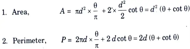
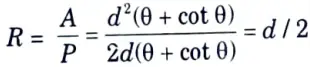
b. Design a concrete lined channel of triangular section to carry a discharge of 45 m3/sec at a slope of 1 in 1000. The side slopes of the channel are 1.5:1 and Manning’s rugosity coefficient for lining material as 0.018.
Ans. Given: Discharge, Q = 45 m3/sec, Longitudinal slope, S = 1 in 1000,
Side slope 1.5:1, Manning’s coefficient, n = 0.018.
To Find: Design concrete lined channel triangular section.
3. Hydraulic mean depth,
4. From Manning’s equation,
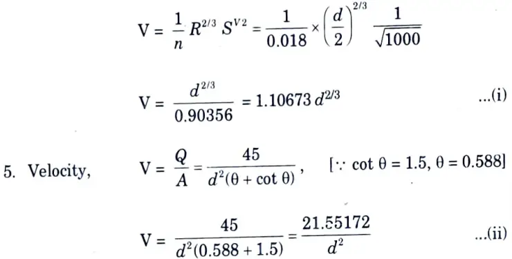
6. From eg. (i) and eq. (ii), we get
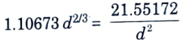
Depth of central portion,
d = 3.04467 m
Section 7 : Confined Aquifer Irrigation & Water Resource Engineering
a. Describe confined and unconfined aquifer with suitable diagram. Derive the expression for the discharge through confined aquifer.
Ans. Unconfined aquifer :
- i. An unconfined aquifer is one in which there is no geological layer restricting the zone of saturation (above the watertable).
- ii. The unconfined aquifer is in direct contact with the atmosphere via the aeration zone.
- iii. The hydraulic pressure head at any location in the unconfined aquifer is equal to the distance from the watertable.
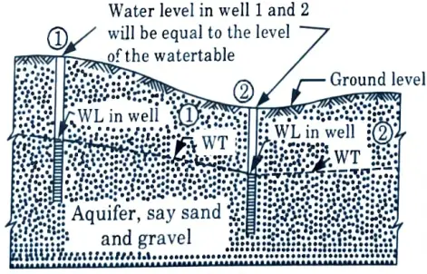
- iv. In an unconfined aquifer, as water is extracted from the aquifer storage, the watertable falls, and when water is returned to the aquifer storage, the watertable rises.
- v. This aquifer is often referred to as the watertable aquifer or the phreatic aquifer.
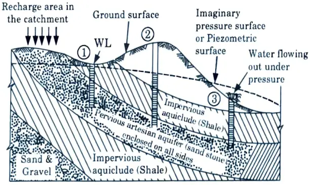
Confined Aquifers :
- i. It is the one that is covered by an impervious covering, also known as an aquiclude.
- ii. Unlike in an unconfined aquifer, water in a confined aquifer does not come into direct contact with the atmosphere.
Derivation :
1. Fig. shows a well completely penetrating a horizontal confined aquifer of thickness B.
2. Consider the well to be discharging a steady flow, Q.
3. The original piezometric head (static head) was H and the drawdown due to pumping is indicated in Fig.
4. The piezometric head at the pumping well is hw, and the drawdown Sw.
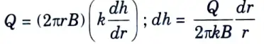
5. At a radial distance r from the well, if h is the piezometric head, the velocity of flow by Darcy’s law is
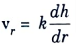
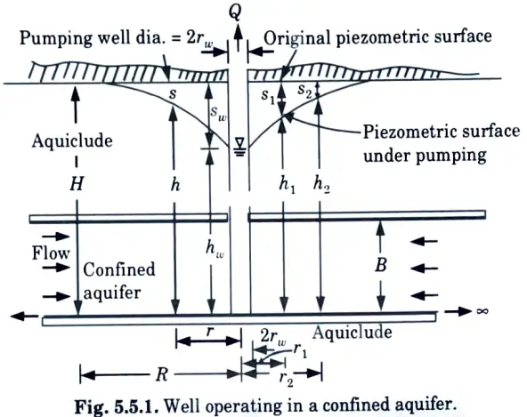
6. The cylindrical surface through which this velocity occurs is 2𝝅rB.
Hence by equating the discharge entering this surface to the well discharge,
7. Integrating between limits r1 and r2 with the corresponding piezometric heads being h1 and h2 respectively,
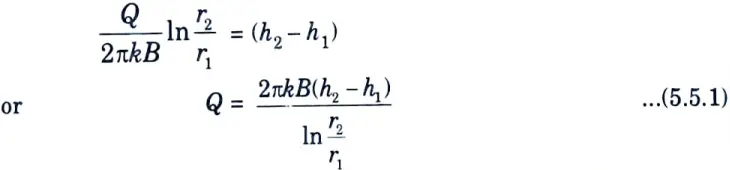
8. This is the equilibrium equation for the steady flow in a confined aquifer. This equation is popularly known as Thiem’s equation.
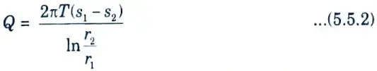
9. If the drawdown s1 and s2 at the observation wells are known, then
by noting that s1 =H – h1, s2 = H-h2 and kB = T
Eq. from (5.5.1), we get
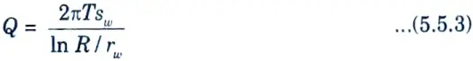
10. Further at the edge of the zone of influence, s2 = 0, r2 = R and h2 = H; at the well wall r1 = rw, h1 = hw and s1 = sw. Eq. (5.5.2) would then be
b. Define following terms :
i. Aquifer.
ii. Aquiclude.
iii. Aquitard.
iv. Aquifuge.
v. Porosity.
Ans. i. Aquifer: Aquifers are permeable formations with characteristics that allow a significant amount of water to travel through them under normal field conditions. As a result, these are the geologic formations where ground water exists (i.e., sands and gravels).
ii. Aquiclude :
- i. It is a geological formation that is essentially impervious to water flow.
- ii. Due to its high porosity, it may be deemed closed to water movement even though it may hold huge amounts of water. An aquiclude is something like clay.
iii. Aquitard :
- i. It is a formation in which only seepage is feasible, hence the yield is small when compared to an aquifer.
- ii. It is partially permeable. Aquitard is a type of sandy clay unit.
- iii. Significant amounts of water may flow through an aquitard to an aquifer below it.
iv. Aquifuge :
- i. It is a geological formation which is neither porous nor permeable.
ii. There are no interconnected openings and hence it cannot transmit water. - iii. Massive compact rock without any fractures is an aquifuge.
v. Porosity: The amount of pore space per unit volume of the aquifer material is called porosity. It is expressed as

where, Vv and V= Volume of voids and porous medium.
1 thought on “Irrigation and Water Resource Engineering: AKTU Question Paper with Answer”