
Newest Aktu Electrical Machines-II Question Paper 2022–2023, Quantum Book Pdf, Key Questions, Easy Language Notes and Question Paper with Solutions, Syllabus of Aktu University
Dudes 🤔.. You want more useful details regarding this subject. Please keep in mind this as well.

Important Questions For Electrical Machines-II:
* Aktu Quantum          * B.tech-Syllabus
* Circulars                     * B.tech AKTU RESULT
* Btech 3rd Year
Section A: Electrical Machines-II Aktu Question Paper Short Questions
a. Name the method of regulation known as optimistic method And why it is so called ?
Ans. 1. The optimistic way is referred to as the armature turn method (MMF method).
2. It returns a value that is less than the starting value. It is dubbed an optimistic technique for this reason.
b. What is the necessity of chording in the armature winding of alternator ?
Ans. 1. It saves the conductor material.
2. It reduces the effects of distorting harmonics.
c. What is the need of parallel operation of two alternators ?
Ans. 1. Load growth: The demand for loads is rising these days as a result of rising electricity use. It’s possible that the current system won’t be able to handle the increased demand, in which case more alternator units would need to be added to match the need.
2. Continuity of service: Several smaller units rather than just one should be running on the system so that in the event of one failing, the others can still service the demand and continuity can be preserved.
d. Define d-axis and q-axis synchronous reactance of the salient pole machine.
Ans. 1. The air gap in the cylindrical rotor synchronous machine is constant. The air gap is very non-uniform due to the salient pole machine’s rotor’s pole structure.
2. Take into account a 2-pole salient pole rotor revolving anticlockwise inside a 2-pole stator as depicted in Fig.
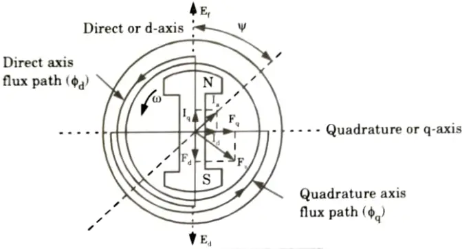
3. The axis along the axis of the rotor is called the d-axis. The axis perpendicular tu d-axis is known as the q-axis. The direct axis flux path involves two small air gaps and is the path of the minimum reluctance. The path shown in Fig. by ɸq has two large air gaps and is the path of the maximum reluctance.
e. Name two types of induction motor based on rotor construction.
Ans. 1. Squirrel-cage induction motor.
2. Wound-rotor or slip-ring induction motor.
f. Calculate the slip for 2-pole, 50 Hz induction motor running at 2950 rpm.
Ans.
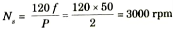
Nr = 2950 rpm
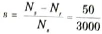
= 0.0167
g. Define crawling in an induction motor.
Ans. Cogging: Cogging or teeth locking refers to the magnetic locking phenomena that occurs between the teeth of the stator and rotor.
Crawling: Crawling of the motor is defined as the tendency of the motor to run at a stable speed as low as one-seventh of the normal speed N and being unable to pick up its regular speed.
h. What are the advantages of skewing rotor bars in cage squirrel induction motor ?
Ans. 1. The skewing of the rotor prevents the crawling effect.
2. The skewing helps in reducing the magnetic hum, and the motor runs quieter.
i. Classify single phase induction motor.
Ans.
- 1. Split-phase motor
- 2. Capacitor-start motor
- 3. Capacitor-start capacitor-run motor
- 4. Permanent split capacitor motor
- 5. Shaded-pole motor.
j. Single phase induction motor is not self-starting. Give reason.
Ans. A pulsing magnetic field is created when the stator winding is linked to a single phase source. Two revolving magnetic fields of similar magnitude but spinning in the opposite directions result from a pulsating magnetic field. The two torques are therefore equal and in opposition. So, at a complete stop, the net torque is zero. A single phase induction motor is not self starting as a result.
Section B: Aktu Quantum Repeated Questions of Electrical Machines-II
a. Discuss the effects of armature reaction on the terminal voltage of alternator at (i). Zero pf lagging (ii) Zero pf leading and (iii) 0.8 pf lagging & (iv) Unity pf. Also, discuss synchronous impedance method for finding voltage regulation of a cylindrical rotor machine.
Ans. A. Effect of armature reaction on the terminal voltage of alternator at:
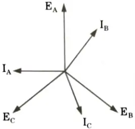
i. Zero pf lagging: Suppose that the alternator is loaded with an inductive load of zero power factor lagging. The phase current IA, IB and IC will be lagging with their respective phase voltages EA, EB and EC by 90°.
ii. Zero pf leading:
1. Suppose that the alternator is loaded with a load of zero power factor leading. The phase currents IA, IB and IC will be leading their respective phase voltages EA, EB and EC by 90°.
2. At time t = 0, the instantaneous values of currents and fluxes are given by

iii. 0.8 pf lagging: The armature reaction has demagnetizing and cross-magnetizing components when the machine produces a current with a lagging power factor.
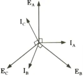
iv. Unity pf:
1. Suppose that the alternator is supplying current at unity power factor. The phase currents IA, IB and IC will be in phase with their respective generated voltage EA, ER and EC as shown in Fig.(a).
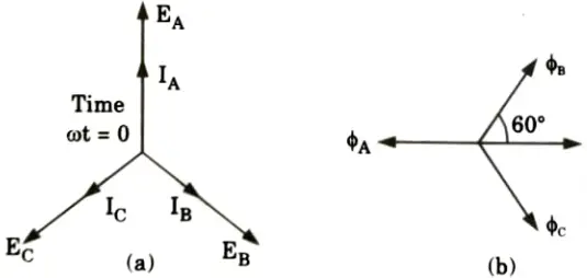
2. The positive directions of fluxes ɸA, ɸB and ɸC are shown in the space diagram of Fig.(b).
B. Synchronous impedance method:
- 1. The result obtained from the OC (open circuit) test and SC (short circuit) test are used to find the regulation by this method.
- 2. This method is called as EMF method because in this method armature resistance drop (Ia Ra drop) and leakage reactance drop (Ia Xa) are actually EMF quantities hence it is known as EMF method.
- 3. The regulation found by this method is always more than found from the test of direct loading. Hence EMF method is therefore called as pessimistic method.
b. Explain in detail hunting phenomenon in synchronous motor. Classify its causes and explain how they can be reduced.
Ans. A. Hunting in 3ɸ synchronous motors:
- 1. A steady-state operation of a synchronous motor is a condition of equilibrium from electromagnetic.
- 2. In the steady state, the rotor runs at synchronous speed, thereby maintaining a constant value of the torque angle 𝛅.
- 3. If there is a sudden change in the load torque, the equilibrium is disturbed, and there is a resulting torque which changes the speed of the motor.
- 4. It is given by
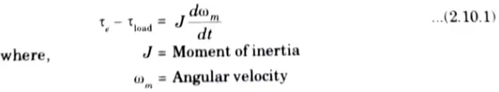
- 5. The electromagnetic torque is given by
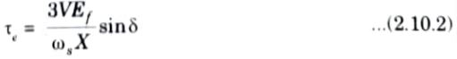
- 6. Since 𝛅 is increased, the electromagnetic torque increases.
- 7. The torque angle 𝛅 is larger than the required value 𝛅1 for the new state of equilibrium. Hence, the rotor speed continues to increase beyond the synchronous speed.
- 8. As a result of rotor acceleration above synchronous speed, the torque angle 𝛅 decreases.
- 9. At the point where motor torque becomes equal to the load torque, the equilibrium is not restored, because now the speed of the motor is greater than the synchronous speed. Therefore the motor continues to swing backwards. The torque angle goes on decreasing.
- 10. When the load angle 𝛅 becomes less than the required value 𝛅1, the mechanical load becomes greater than the developed power. Therefore, the motor starts to slow down. The load angle is increased again. Thus, the rotor swings or oscillates around synchronous.
- 11. This phenomenon of oscillation of the rotor about its final equilibrium position is called hunting.
- 12. Since during rotor oscillations, the phase of the phasor Ef changes relative to phasor V, hunting is also known as phase swinging.
B. Causes of hunting:
- 1. Sudden changes of load.
- 2. Faults occurring in the system.
- 3. Sudden changes in the field current.
- 4. Cyclic variations of load torque.
C. Reduction of hunting:
- 1. Damper winding or damping:
- a. A relative motion between the damper winding and the revolving magnetic field is produced when the rotor begins oscillating, or when hunting begins.
- b. The damper winding experiences emf as a result of this relative motion.
- c. In accordance with Lenz’s law, induced emf always points in the opposite direction of the cause that caused it. Hunting is the root cause.
- d. Hence, such an induced emf opposes hunting. The induced emf attempts to immediately stop the oscillations. As a result, damper winding reduces hunting.
- 2. Use of flywheels: A big, hefty flywheel is included with the prime mover. This raises the prime mover’s inertia and aids in keeping the rotor speed constant.
- 3. By designing synchronous machines with suitable synchronizing power coefficients.
c. Sketch and derive the torque-slip characteristics of a 3-phase induction motor indicating starting and maximum torque and the operating region. A 3-phase induction motor has a starting torque of 100 % and maximum torque of 200 % of full load torque. Determine slip at maximum torque and full load slip.
Ans. A. Torque-slip characteristics: The torque-slip characteristics are divided into three regions:
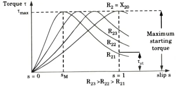
a. Low-slip region: At synchronous speed s = 0, therefore, the torque is a zero. When speed is near to synchronous speed, the slip is very low and (sX20)2 is negligible in comparison with R2. Therefore,
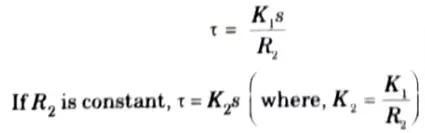
Relation shows that torque is proportional to slip. Hence, when slip is small, the torque-slip curve is straight line.
b. Medium-slip region: As slip increases, (sX20)2 becomes large, so that R22 may be neglected in comparison with (sX20)2 and
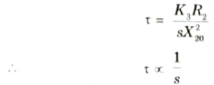
The torque-slip characteristic is represented by a rectangular hyperbola.
c. High-slip region: After the maximum torque is reached, the torque starts to diminish. As a result, the motor begins to sputter and eventually stops. In order to prevent damage from overheating at this point, the overload protection must promptly disconnect the motor from the supply.
B. Numerical:
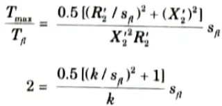
1. Full load torque,
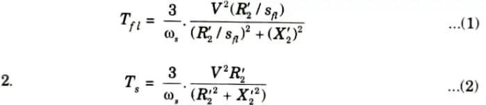
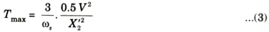
3. Maximum torque,
4. Dividing eq. (3) by eq. (2)
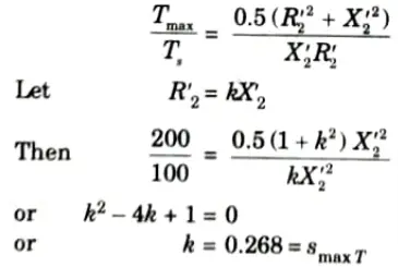
The second value of smaxT = 3.73 is rejected as it pertains t0 an abnormally high-resistance rotor (which would be highly inefficient).
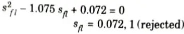
5. Dividing eq. (3) by eq. (1)
d. A 3-phase delta connected cage type induction motor when connected directly to 400 V, 50 Hz supply takes a starting current of 100 A in each stator phase calculate (i) The line current for DOL starting, (ii)) Line and phase starting currents for star-delta starting, (iii) Line and phase currents for 70 % tapping on auto transformer starting.
Ans. i. Line current for DOL starting:
ii. Line and phase starting currents for star delta starting:
a. Phase voltage,
b. This will produce a phase current of,
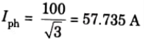
This is because voltage is reduced by 1/ √3 hence current will also be reduced by 1/ √3
c. Starting phase current = 57.735 A
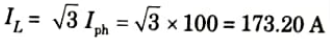
d. In star connection, IL = Iph
∴ Starting line current = 57.735 A
iii. Line and phase starting currents for a 70 % tapping on auto-transformer starting:
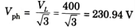
a. The auto-transformer is star connected. So phase voltage of auto-transformer is 400/ √3 = 230.94 V.
b. The line voltage for delta connected stator is 0.7 x 400 = 280V
c. The phase voltage for delta connected stator is 280V.
d. The 400 V circulates 100 A phase current hence 280 V will circulate a phase current of
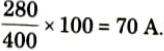
e. Starting phase current of motor = 70A
f. Starting line current of motor = √3 x 70 = 121.243 A
g. Supply line current = 0.7 x 121.243 = 84.87 A
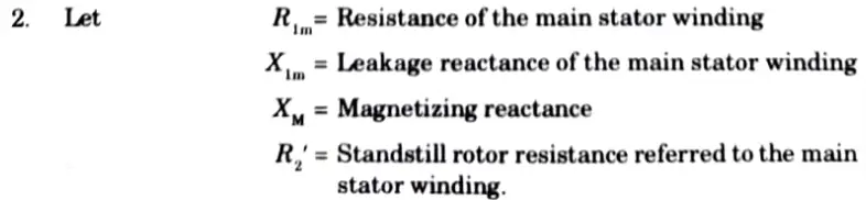
e. Develop equivalent circuit diagram of single-phase induction motor based on double revolving field theory.
Ans. 1. Fig. shows the equivalent circuit at standstill with effect of forward and backward rotating fluxes separated.
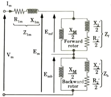
3. Fig. shows an equivalent circuit under running condition.
4. At stand-still the air-gap flux can be resolved into two equal and opposite magnetic fields within the motor. R2’ and X2’ can be split into two parts, also the voltages Emf and Emb are equal at stand still.
5. Now, under running condition, at the slip s the terms are changed like resistive term in

Section 3: Aktu Long Questions Electrical Machines-II
a. Derive emf equation for an alternator. Also, develop expressions of pitch factor and distribution factor.
Ans. A Emf equation:
1. The size of the induced emf in the conductor that results from the cutting of the magnetic field by a conductor relies on the pace at which the flux is being cut.
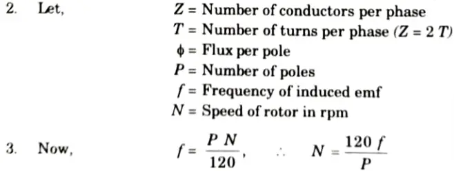
4. In one revolution, each conductor is cut by flux of P ɸ and time to cut this flux is 60/N seconds.
∴ Average rate of cutting the flux
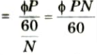
5. Average emf induced in one conductor

6. Average emf induced in Z conductor
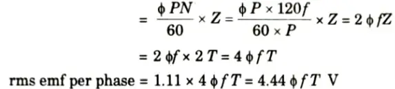
This is for full pitched and concentrated winding.
7. But for fractional pitch and distributed winding; coil span factor (Kc) and distribution factor (Kd) are taken into account.

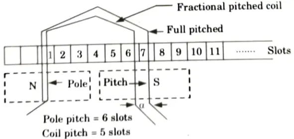
B. Expression of pitch factor and distribution factor:
Fractional pitched coil (or Short pitched coils):
This indicates the pitch less than full pitch i.e., less than pole pitch (i.e., less than 180° electrical).
Distribution factor or Breadth Factor, (Kd):
1. It is ratio of vector sum of the emfs when coils are distributed to the resultant emf with coils is concentrated.
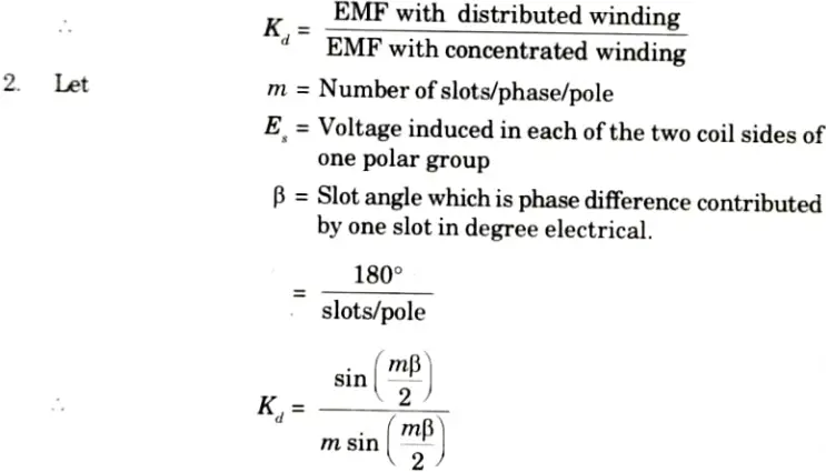
3. The distributed factor is also less than unity and it is about 0.9.
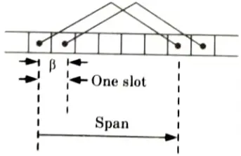
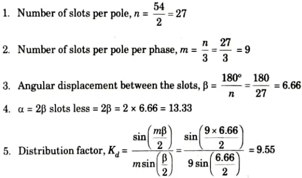
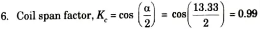
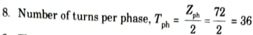
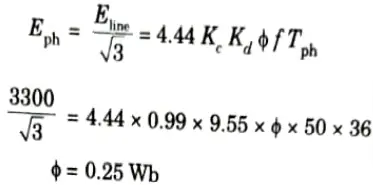
b. A 3-phase, 2-pole, 50 Hz, star-connected turbo-alternator has 54 slots with 4 conductors per slot. The pitch of the coil is 2 slots less than the pole pitch. Determine the useful flux per pole required to generate a line voltage of 3.3 kV.
Ans. Given: P = 2, f = 50 Hz, Number of slots = 54, conductors per slot = 4, VL = 3.3 kV
To Find: Flux per pole.
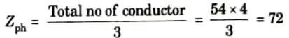
7. Number of conductor per phase
9. Then voltage generated per phase,
Section 4: Electrical Machines-II Quantum Book Pdf
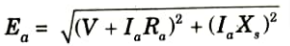
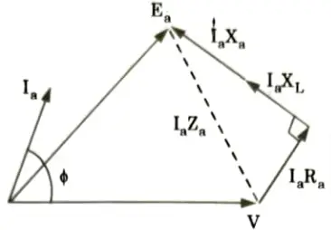
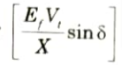
a. Draw and explain the phasor diagram of a salient pole synchronous generator supplying full-load lagging current. Show that the power output per phase is given by
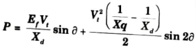
where the notations have their usual meaning.
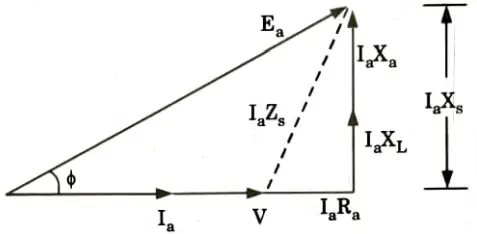
Ans. A. Phasor diagram of a salient pole synchronous generator:
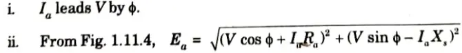
a. At unity power factor:
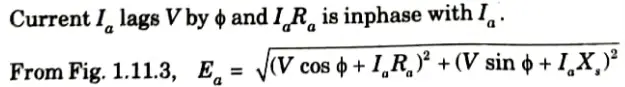
i. Current Ia is inphase with V and IaRa drop is inphase with Ia.
iii. From Fig.
b. For lagging power factor:
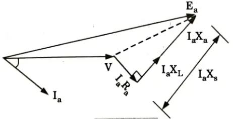
c. For leading power factor:
B. Power output:
- 1. Consider a synchronous generator transferring a steady power P0 at a steady load angle 𝛅0.
- 2. Suppose that, due to a transient disturbance, the rotor of the generator accelerates, so that the load angle increases by an angle d𝛅.
- 3. The operating point of the machine shifts to a new constant-power line and the load on the machine increases to P0 + 𝛅P.
- 4. Since the steady power input remains unchanged, this additional load decreases the speed of the machine and brings it back to synchronism.
- 5. Similarly, if due to a transient disturbance, the rotor of the machine retards, so that the load angle decreases.
- 6. The operating point of the machine shifts to a new constant power line and the load on the machine decreases to P0 + 𝛅P.
- 7. The decrease in load causes the rotor to accelerate since the steady power input stays the same. As a result, the machine synchronizes once more.
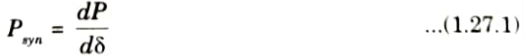
- 8. Depending on the change in power transfer for a specific change in load angle, this corrective action’s efficacy will vary. Synchronizing power coefficient provides a measure of efficiency.
- 9. It is defined as the rate at which the synchronous power P varies with the load angle 𝛅. It is also called stiffness of coupling, rigidity factor, or stability factor and is denoted by Psyn.
10. Power output per phase of the cylindrical rotor generator
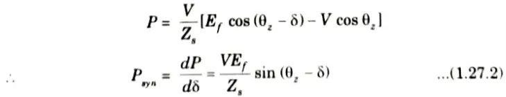
11. The synchronizing torque coefficient
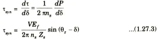
12. For a cylindrical rotor machine, neglecting saturating and stator resistance eq. (1.27.2) and (1.27.3) become
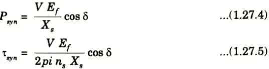
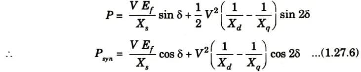
13. For a salient-pole machine
b. Explain how a synchronous motor operates as a synchronous condenser with the help of phasor diagram. A small industrial load of 500 kW at 0.6 pf lagging is supplied from a 3300 V, 3-phase, 50 Hz system. It is desired to raise the pf of the entire system to 0.8 lagging by means of a synchronous motor, which is also driving a pump so that the synchronous motor takes 100 kW from the lines. Determine the rating of synchronous motor.
Ans. A. Synchronous condenser:
- 1. The excitation is referred to as normal when the motor power factor is unity.
- 2. The motor runs at a leading power factor due to overexcitation.
- 3. It runs at a trailing power factor due to under-excitation.
- 4. The motor requires a current that is nearly 90° ahead of the voltage when it is operated at no-load with overexcitation.
- 5. Because it functions in a manner similar to a capacitor under these conditions, the synchronous motor is also referred to as a synchronous capacitor.
- 6. Synchronous motors function devoid of mechanical loads. By altering the excitation of its field winding, it can produce or absorb reactive voltamperes (VAr).
- 7. By overexciting its field winding, it can be made to take a leading current.
- 8. In this situation, it provides inductive VAr (or absorbs capacitive VAr). If it is under-excited, it absorbs an inductive current and supplies capacitive VAR instead.
- 9. As a result, by adjusting the excitation, a synchronous capacitor’s current draw can be smoothly changed from lagging to leading.
Fig. shows an elementary energy system network:
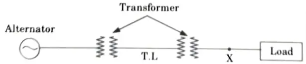
10. Let Vt is the terminal voltage at point A and Ef is the alternator excitation voltage. I is the load current of power factor cos 𝜃 and X is the total reactance between Ef and Vt, then phasor diagram for this system is as shown in Fig.
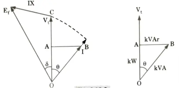
11. At the point X, the load is OA kW proportional to I cos 𝜃. The apparent power is OB kVA proportional to I and load kVAr is AB proportional to I sin 𝜃.
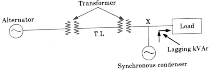
12. With the installation of synchronous condenser at X, Fig. suppose that the load power factor at X is improved to unity then lagging kVAr required by the load and equal to AB are locally supplied by the synchronous condenser as OG = AB as shown in Fig.
13. In this manner, the energy system network between alternator and point A is relieved of lagging kVAr. The current is reduced from OB to OA and the voltage at point A rises from OC to OD function the same Ef.
14. Since the system current has reduced it would result in decreased I2R loss and therefore better system efficiency. Thus with the help of a synchronous condenser more power
can be delivered to load because Vt has increased; power factor of the system and its efficiency are improved and consequently the general operation of the load apparatus becomes better.
15. Power factor at point A would be close to unity if synchronous condenser supply is lagging kVAr a little bit less than AB, and even then, efficiency and voltage regulation would increase.
B. Numerical:
1. Power factor, cos 𝛟 of the existing load is 0.6 lagging
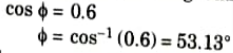
2. From Fig.
3. Input to the synchronous motor
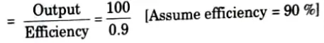
= 111.11 kW
4. Total load on the system
= 500 + 111.11 = 611.11 kW
5. Now overall power factor of the load is to be raised to 0.8 lagging
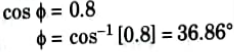
6. From Fig.
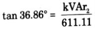
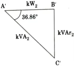
kVAr2 = 611.11 x tan 36.86°
= 458.16
7. The lagging kVAr neutralized by the synchronous condenser are given by,
= kVAr1 – kVAr2
= 666.66 – 458.16
= 208.5
8. Thus for the synchronous condenser
kW input = 111.11
9. Leading kVAr supplied by the motor
= 208.5
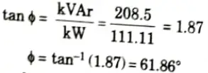
10. Power factor of the synchronous motor,
pf = cos 61.86° = 0.47
11. The kVA rating of the synchronous motor,
kVA cos 𝛟 = kW
Section 5: Electrical Machines-II Quantum Aktu Notes Pdf
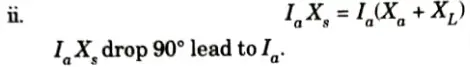
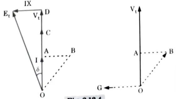
a. Explain the (i) effect of varying of excitation of a synchronous generator connected to infinite busbar on the power factor, armature current and load angle and (ii) effect of load changes on a synchronous motor with the help of phasor diagrams.
Ans. i. Effect of varying of excitation of a synchronous generator:
A. Infinite bus:
An infinite bus is a power system that is so big that no matter how much actual and reactive power is used or supplied to it, its voltage and frequency remain constant.
B. Effect on operation:
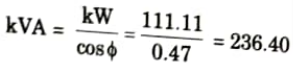
- 1. Let us consider that alternator is supplying power to an infinite bus which has induced emf E, power angle 𝛅 and working at unity power factor with current I.
- 2. With mechanical power input to the alternator remaining constant, the power given by EV/X sin 𝛅 will remain constant.
- 3. If by varying excitation induced emf E is increased to E1 then the load angle will also change from 𝛅 to 𝛅1.
- 4. From the phasor diagram it can be determined as E1 sin 𝛅1 = E sin 𝛅 as V and Xs are constant. The drop due to synchronous reactance also increases and armature current increases from I to I1.
- 5. This current has two components one real component and other quadrature component. This quadrature component is nothing but demagnetizing component. This will result in lagging power factor cos 𝛟1.
- 6. Similarly if the excitation is decreased so that induced emf reduces from E to E2 with corresponding change in power angle from 𝛅 to 𝛅2. The armature current in this case will be I2 which has real component and magnetizing component which results in leading power factor cos 𝛟2 This can be represented in the phasor diagram shown in Fig.
7. From the phasor diagram it can be seen that
Multiplying by V throughout,
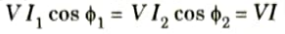
8. This suggests that the power sent to the bus will not fluctuate. Consequently, the active power is unaffected by changing the field excitation. Yet, as depicted in Fig., a change in excitation causes a commensurate change in operational power factor.
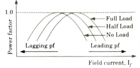
ii. Effect of load changes on a synchronous motor:
- 1. Let us assume that the motor is operating at no load.
- 2. If the field current is increased from this small value, the armature current Ia decreases until the armature current becomes minimum and the motor is operating at unity power factor. Upto this point the motor was operating at a lagging power factor.
- 3. If the field current is increased further, the armature current increases again and the motor starts to operate at a leading power factor.
4. If a graph is plotted between armature current Ia and field current If at no load, the lowest curve in Fig. is obtained. - 5. If this procedure is repeated for various increased loads, a family of curves is obtained as shown in Fig.
- 6. Since the shape of these curves resembles the letter “V”, these curves are commonly known as V-curves of a synchronous motor.
- 7. The V-curves are useful in adjusting the field current. Increasing the field current If beyond the level for minimum armature current Ia results in leading power factor and vice-versa.
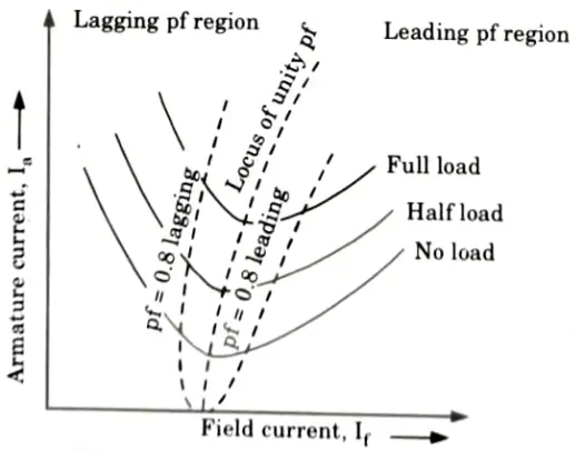
- 8. As a result, the reactive power provided to or consumed from the power system can be regulated by adjusting the field current of a synchronous motor.
- 9. Plotting the power factor against the field current yields a series of curves. As seen in Fig., these are inverted V-curves.
b. Draw power flow diagram showing how electrical input is converted in to mechanical power output in an induction motor. A 4-pole, 400 V, 3-phase, 50 Hz squirrel cage induction motor runs at speed of 1450 rpm at 0.85 pf lagging developing 11 kW power. The stator losses are 1100 W and mechanical losses are 400 W. Calculate (i) slip (ii) rotor copper loss (iii) rotor frequency (iv) line current (v) efficiency.
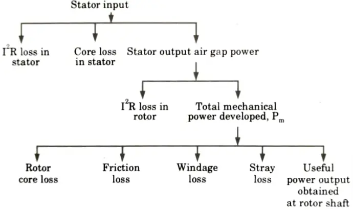
Ans. A. Power flow diagram:
Mechanical power developed, Pm:
1. If rotor copper losses are subtracted from rotor input power Pg the remaining power is converted from electrical to mechanical form. This is called developed mechanical power, Pm.
2. Developed mechanical power = rotor input – rotor copper loss
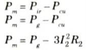
D. The output of the motor is given by:
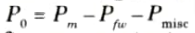
P0 is also called shaft power or output mechanical power of an induction motor. The power flow diagram is shown in Fig.
B. Numerical:
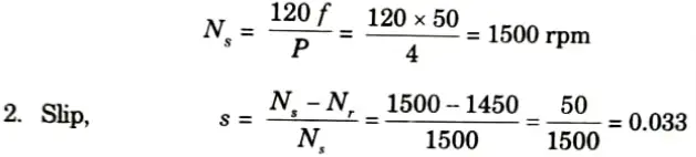
Given: P= 4, V= 400 V, Nr = 1450, pf = 0.85 lagging, Pout =11 kV, stator loss = 1100W, mechanical loss = 400 W
To Find: i. Slip
ii. Rotor copper loss
iii. Rotor frequency
iv. Line current
v. Efficiency
1. Synchronous speed,
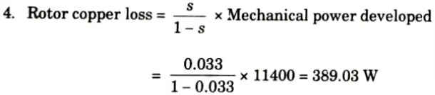
3. Mechanical power developed
= 11 x 103 + 400 = 11400 W
5. Rotor efficiency = sf = 0.33 x 50 = 16.5 Hz
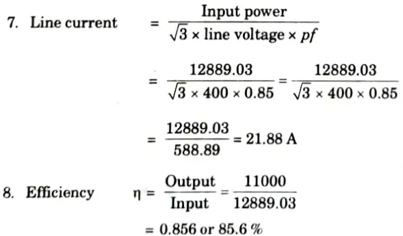
6. Input to stator or motor = Mechanical power developed + Rotor copper loss + Stator loss
= 11400 + 389.03 + 1100 = 12889.03 W
Section 6: Aktu Question Paper Solved of Electrical Machines-II
a. What is the necessity of starter in induction motor ? With the help of neat diagram, discuss auto-transformer and star-delta method of starting a squirrel cage induction motor. Also, discuss the limitations of these methods.
Ans. A. Necessity of starter in induction motor:
- 1.A spinning magnetic field is created and the rotor of a three-phase induction motor begins to rotate when the supply is connected to the stator. A three-phase induction motor can so start on its own.
- 2. At the time of starting the motor slip is unity and the starting current is very large
- 3. The purpose of a starter is not to start the motor. The purpose of starter is:
- i. To reduce the heavy starting current.
- ii. To provide over-load and under-voltage protection.
B. Star-delta starting method:
1. Fig. shows the connection of a three-phase induction motor with a star-delta starter.
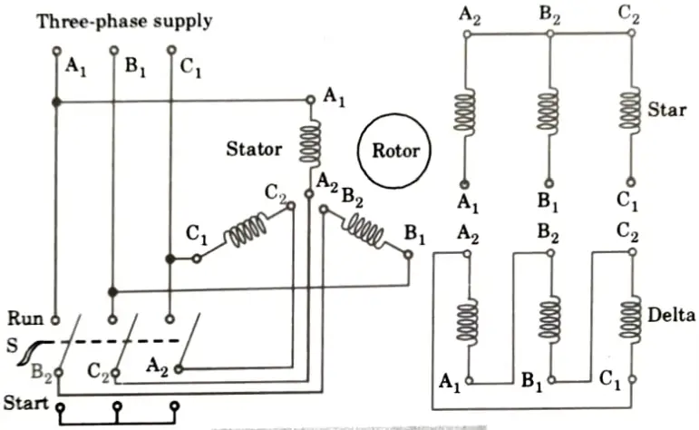
2. The stator windings are connected in a star shape when the switch S is in the start position.
3. The changeover switch S is quickly moved to the run position, connecting the stator windings in delta, while the motor accelerates to, say, 80% of its rated value.
4. The line current consumed by the motor at startup is decreased to one-third by connecting the stator windings first in star and then in delta, as opposed to starting current in the windings linked in delta.
5. At the time of starting when stator winding are star connected, each stator phase gets a voltage

Since, the torque developed by an induction motor is proportional to the square of the applied voltage, star-delta starting reduces the starting torque to one-third of that obtainable level by direct-delta starting.
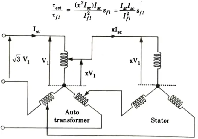
C. Auto-transformer method:
1. Auto-transformer starter is suitable for both star and delta connected motors. In this method, by using a 3𝛟 auto-transformer tapping, the starting current is limited.
2 Auto-transformer starter connection diagram is shown in Fig.
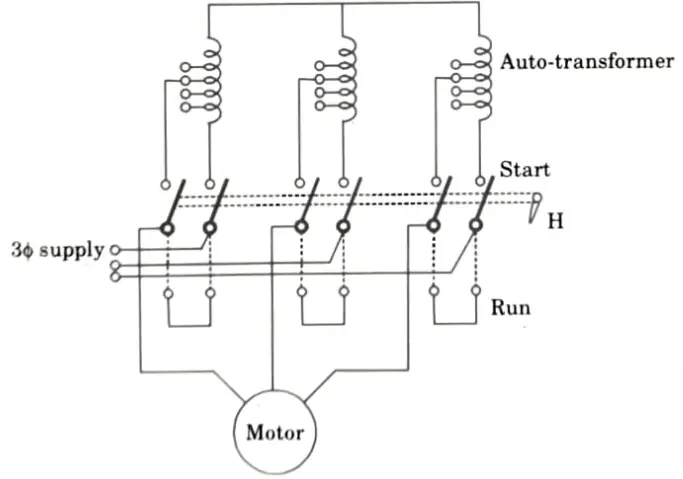
3. With auto-transformer, per phase starting current in motor winding
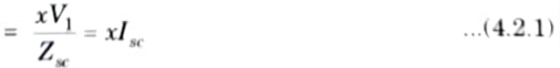
Where, x = Transformation ratio
4. If no load current = 0A
then per phase input VA = per phase output VA
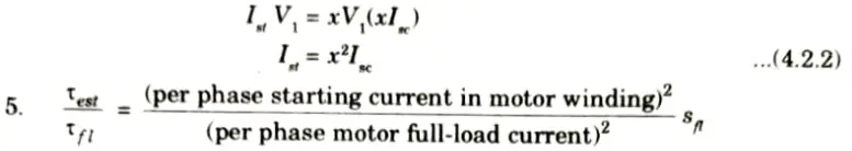
5. From eq. (4.2.1),
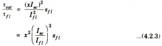
8. From eq. (4.2.2) and (4.2.3),
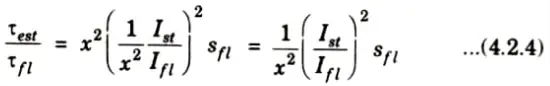
9. From eq. (4.2.3),
D. Limitations:
- a. Star delta:
- i. Low starting torque
- ii. Break in supply
- b. Auto transformer:
- i. Quite expensive
- ii. The control and power circuits are quite complex.
b. With the help of circuit diagram discuss speed control of induction motor by (i) consequent pole method (ii) Rotor rheostat control and (iii) stator voltage control.
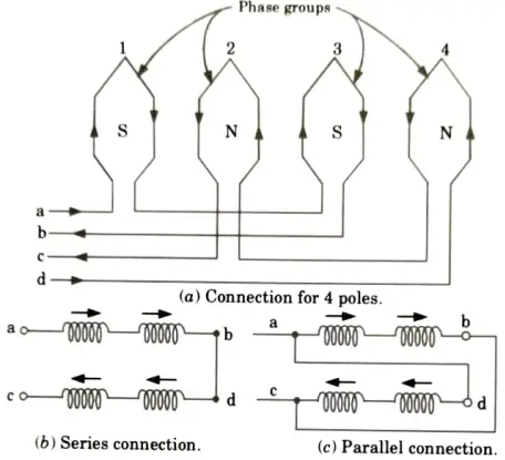
Ans. i. Pole method:
- 1. In this method a single stator winding is divided into few coil groups. The terminals of all these groups are brought out. The number of poles can be changed with only simple changes in coil connections.
- 2. Fig. shows one phase of a stator winding consisting of 4 coils divided into two groups a – b and c – d.
- 3. Group a – b consists of odd-numbered coils (1, 3) and connected in series. Group c – d has even numbered coils (2, 4) connected in series.
- 4. The terminals a, b, c, d are taken out as shown in Fig. The coils can be made to carry current in the given direction by connecting coil groups either in series or parallel shown in Fig.(b) and Fig.(c) respectively.
- 5. By choosing a suitable combination of series or parallel connections between coil group of each phase, speed change can be obtained.
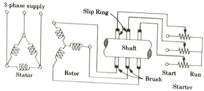
ii. Rotor rheostat (resistance) control:
- 1. By adding external resistance to the rotor circuit of a wound induction motor through slip rings, the speed can be adjusted.
- 2. Although the maximum torque is independent of rotor resistance, yet the exact location of 𝛕max is dependent on it. Greater the value of R2, greater is the value of slip at which maximum torque occurs.
- 3. The motor’s pull-out speed reduces as the rotor resistance rises, but the maximum torque doesn’t change. Consequently, control is given from the rated speed to lesser speeds using this manner.
- 4. This speed control technique is fairly straightforward. With low amounts of slip, it is feasible to have a big starting torque, a low starting current, and a significant pull-out torque.
Diagram of rotor rheostat (resistance) control:
iii. Stator voltage control:
- 1. By altering the supply voltage, a three-phase induction motor’s speed can be changed.
- 2. The slip at maximum torque is independent of supply voltage and is proportional to the square of the torque created.
- 3. Changes in the supply voltage have no effect on synchronous speed either. Fig. displays the torque-speed characteristics of a three-phase induction motor with a changing supply voltage.
- 4. In order to adjust speed, the providing voltage is changed until the load’s required torque is created at the desired speed.
- 5. Supply voltage current and voltage are inversely correlated, and the torque created is proportional to the square of the voltage. As a result, the motor’s torque decreases as voltage is decreased to reduce speed for the same current.
- 6. As a result, this approach is appropriate for applications where the torque of the load decreases with speed, such as a fan load.
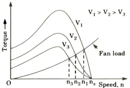
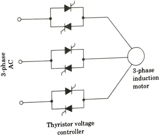
Diagram of stator voltage control: Three pairs of back-to-back coupled thyristors, one pair in each phase, are needed for a three-phase induction motor (Fig.). The voltage of each thyristor pair’s coupled phase is controlled. By altering the thyristors’ conduction duration, speed can be controlled.
Section 7: Electrical Machines-II Aktu Repeated Important Questions
a. Write short notes on (i) Capacitor start motor (ii) Shaded pole motor and (iii) Repulsion motor.
Ans. i. Capacitor start motor:
- 1. Fig.(a) shows the connections of a capacitor-start motor. It has a cage rotor and its stator has two windings namely, the main winding and the auxiliary winding (starting winding).
- 2. The two windings are displaced 90° in space. A capacitor CS is connected in series with the starting winding. A centrifugal switch SC is also connected as shown in Fig.(a).
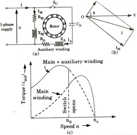
- 3. By choosing a capacitor of the proper rating the current IM in the main winding may be made to lag the current IA in the auxiliary winding by 90°.
- 4. Thus, a single-phase supply current is split into two phases to be applied to the stator windings. Thus the windings are displaced 90° apart in time phase.
- 5. Therefore the motor acts like a balanced two-phase motor. As the motor approaches its rated speed, the auxiliary winding and the starting capacitor CS are disconnected automatically by the centrifugal switch SC mounted on the shaft.
ii. Shaded pole motor:
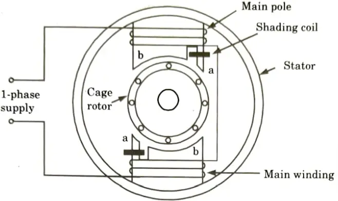
- 1. A shaded-pole motor is a simple type of self starting 1𝛟 induction motor. It consists of a stator and a cage-type rotor.
- 2. Salient poles make up the stator. Each pole has a side slot, and the smaller section of the letter “a” is fitted with a copper ring. It is known as the shadowed pole. The ring, often referred to as a shading coil, is typically a single-turn coil.
- 3. Alternating flux is created in the field core when alternating current flows in the field winding. A portion of this flux interacts with the shading coil, which functions as a transformer secondary that has been short-circuited.
- 4. The shading coil experiences an induced voltage that causes a current to flow through it. A flux that is in opposition to the primary core flux is created by the induced current.
- 5. As a result, the flux in the shaded area of the pole lags behind the flux in the unhindered area.
- 6. The main flux and the shaded pole flux are both moved in space at the same time. This space’s displacement is under 90°.
- 7. As the two fluxes are separated in time and space, the necessary elements are created for the formation of a rotating magnetic field.
- 8. The cage rotor develops a beginning torque as a result of the rotating flux. This revolving field’s (flux’s) direction is from the pole’s unshaded area to its shaded area.
- 9. It is impossible to reverse the direction of rotation in a shaded-pole motor.
iii. Repulsion motor: This particular type of single-phase AC motor functions as a result of the attraction between like poles.
Construction:
- 1. The stator of this motor carries a single-phase exciting winding. The rotor carries an ordinary distributed DC type winding, connected to the commutator at one end.
- 2. The brushes are short circuited on themselves and are not connected directly to the supply circuit Fig.
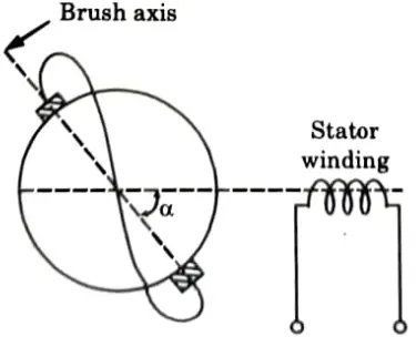
- 3. When 𝛂 = 90°, no mutual inductance between stator and rotor windings. Consequently, the voltage across the brushes is zero, rotor-induced currents are zero hence electromagnetic torque developed is zero.
- 4. When 𝛂 = 0°, the mutual inductance between two windings is maximum, so the large rotor currents produce rotor mmf opposite to the stator mmf since two mmfs are along the same axis, the torque developed is zero.
- 5. Thus when 𝛂 = 0° or 90° motor not in run position but when 𝛂 ≠ 0 (or 𝛂 ≠ 90°), due to net induced voltage, electromagnetic torque is produced and rotor runs.
- 6. If the stator mmf at any instant is directed from A to B, then the rotor induced mmf must have a component opposite to the stator mmf at the same instant, i.e., the rotor induced mmf must be directed from C to D in Fig.(c).
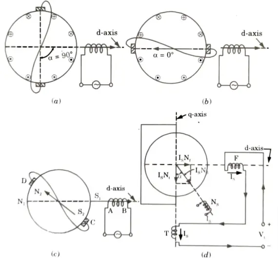
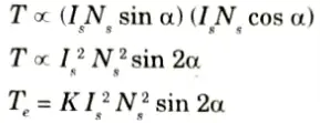
- 7. The stator polarity at A is S1 and at the same instant, rotor-induced polarity at C is S2. Repulsion between like poles S1, S2 and N1, N2 results in the clockwise direction of rotation.
- 8. Now, electromagnetic torque ∝ (stator d-axis mmf) x (rotor q-axis mmf)
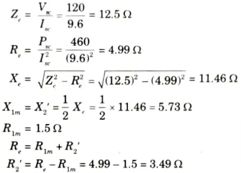
b. A 220 V, 1 phase induction motor give the following test results:
Blocked rotor test : 120 V, 9.6 A, 460 W
No load test : 220 V, 4.6 A, 125 W
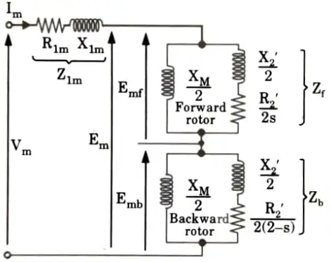
The stator winding resistance is 1.5 Ω and during blocked rotor test, the starting winding is open. Determine equivalent circuit parameters.
Ans. Given: VL = 230 V
Blocked-rotor test: Vsc = 120 V, Isc = 9.6 A, Psc = 460 W
No-load test: V0 = 230 V,. I0 = 4.6 A, P0 = 125 A, R1m = 1.5 Ω
To Find: X2’, R2’, R0 and X0.
1. Blocked-rotor test:
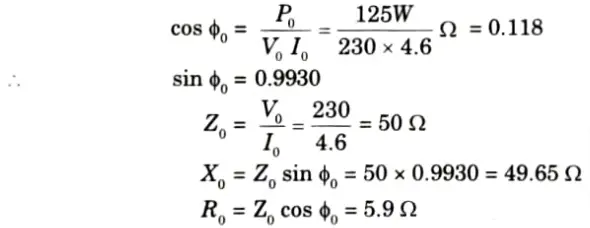
2 No-load test:
7 thoughts on “Electrical Machines-II Aktu Question Paper, Notes, Quantum Book Pdf 2022-23”