
Learn more about Information System: Analysis, Design and Implementation from BCA solved question papers. Discover the fundamentals of data modelling and system development, and obtain knowledge for successful implementation.
Dudes 🤔.. You want more useful details regarding this subject. Please keep in mind this as well.

Important Questions For Information System: Analysis, Design and Implementation:
* Important Short Questions
* Solved Question Paper
* Syllabus
Section A: Information System: Analysis, Design and Implementation Very Short Question Answers
Q1. Define the importance of joint application development for requirements elicitation.
Ans. Joint Application Development (JAD) enables clients to participate in the development of their applications through a series of workshops while maintaining complete project autonomy. JAD sessions are necessary when a firm requires some technical advice from technical experts.
Q2. What do you mean by technical feasibility and economic feasibility?
Ans. Technical Feasibility: Technical issues can only be resolved at the phases of our life cycle during which technical feasibility may be assessed, i.e. following the evaluation and design phases. Technically, very little is impossible today. As a result, technological feasibility considers what is feasible and reasonable.
Economic Feasibility: The viability of a project from an economic perspective is crucial. Early on in the project, determining if the potential rewards of solving the issue are desirable is the extent of economic feasibility research. At that point, it is nearly difficult to estimate costs because neither the end-user’s requirements nor potential technical alternatives have been determined. However, the analyst can evaluate the costs and advantages of each option once particular criteria and solutions have been determined. A cost-benefit analysis is what is being done here.
Q3. Define some properties of an object.
Ans. Some properties of an object are:
- (a) An object has identity (each object is a distinct individual).
- (b) An object has state (it has various properties, which might change).
- (c) An object has behaviour (it can do things done to it).
Q4. Define the term group dynamics.
Ans. There are two terms in “group dynamics”: group and dynamics. Basically, a group is a grouping of two or more people. The word “dynamics” is a Greek word that means “force.” The interactions of forces among group members in a social setting are hence the focus of group dynamics.
Q5. What do you mean by system development life cycle?
Ans. System analysts, software engineers, programmers, and end users construct information systems and computer applications using a System Development Life Cycle (SDLC), a logical procedure, to address business needs and challenges. The term “application development life cycle” is occasionally used.
Section B: Information System: Analysis, Design and Implementation Short Question Answers
Q6. Discriminate between data flow model and control flow model with suitable example.
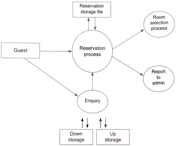
Ans. Data Flow Model: A data flow model is a diagram that shows how information moves through a system and how it is exchanged. By outlining the steps used to move data from input to file storage and report production, data flow models are used to visually portray how data flows through an information system. A data flow diagram is another name for a data flow model.
Data flow modelling can be used to identify a variety of different things, such as:
- (a) Information that is received from or sent to other individuals, organisations, or other computer systems.
- (b) Areas within a system where information is stored and the flows of information within the system are being modeled.
- (c) The processes of a system that act upon information received and produce the resulting outputs.
For examples: Given below figure shows data flow model:
Control Flow Model: An appropriately annotated geometric figure is used to represent operations, data, or equipment, and arrows are used to indicate the sequential flow from one to the other. A control flow diagram can also include subdivision to show sequential steps, if-then-else conditions, repetition conditions, and case conditions.
An example of a control flow statement is an if/else statement, shown in the following JavaScript example, In this example, if the variable x is set equal to 1, then the code in the curly brackets { } after the If statement is executed. Otherwise, the code in the curly brackets after the ‘else’ statement is executed.
Q7. Discuss the principles for user interface design.
Ans. User Interface Design Principles: The requirements, background, and skills of system users are taken into consideration during user interface design. Designers must be conscious of the cognitive and physical limitations of individuals and acknowledge that mistakes are made by all. Interface designs are supported by user interface design principles, albeit not all concepts apply to all designs.
Following are the user interface design principles:
- 1. User Familiarity: Instead of computer notions, the interface should be built on user-oriented language and concepts. An office system, for example, should employ ideas such as letters, papers, folders, and so on rather than directories, file identifiers, and so on.
- 2. Consistency: The system should display an appropriate level of consistency. Commands and menus should have same format, command punctuation should be similar, etc.
- 3. Minimal Surprise: If a command operates in a known way, the user should be able to predict the operation of comparable commands.
- 4. Recoverability: The system should provide same resilience to user errors and allow the user to recover from errors. This might include and undo facility, confirmation of destructive actions, etc.
- 5. User Guidance: Some user guidance such as help system, online manuals, etc. should be supplied.
- 6. User Diversity: Interaction facilities for different types of users should be supported. For example, some users have reading problems due to weak sight and so larger text should be available.
Q8. What is information requirement analysis? Discuss the necessary steps to design a data flow diagram.
Ans. The process of determining user expectations for a new or upgraded product is known as information requirement analysis. These characteristics, known as needs, must be quantitative, relevant, and comprehensive.
Requirements analysis is a team effort that demands a combination of hardware, software and human factors engineering expertise as well as skills in dealing with people.
Steps to Design Data flow Diagram:
The steps for constructing data flow diagrams are as follows:
- 1. Build the context diagram, including all external entities and the major data flow to or from them.
- 2. Create diagram level-0 by analysing the major activities within the context process. Include the external entities and major data stores.
- 3. Decompose to a child diagram (level-1 DFD) for each complex process on diagram 0.
- 4. Decompose level-1 processes into level-2 DFDs and decompose further, if needed.
- 5. Balance and validate DFDs to ensure completeness and correctness.
Section C: Information System: Analysis, Design and Implementation Detailed Question Answers
Q9. Give the answer of the following questions:
(i) Differentiate between logical design and physical design with suitable example.
Ans. Differences between Logical Design and Physical Design
| S. No. | Logical design | Physical design |
| 1. | It explains the data independently of how it will be physically implemented in the database. | It represents how the actual database is built. |
| 2. | Defines the data elements and their relationship. | Developing the actual database. |
| 3. | Simpler than the physical design. | Complex than the logical design. |
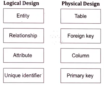
For example: Logical design compared with physical design.
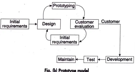
(ii) With a suitable diagram explain the working of Prototype model of software development.
Ans. The Prototype Software Development Model: In this paradigm, a prototype (an early approximation of a final system or product) is produced, tested, and then refined until an acceptable prototype is obtained, from which the whole system or product can now be developed.
Q10. What is capability maturity model? Define the five levels of process maturity with example.
Ans. Capability Maturity Model Integration (CMMI): It is a process model that defines what an organisation should do to encourage habits that lead to higher performance. The CMMI specifies the most critical elements required to produce excellent products or deliver outstanding services and puts them all up in a complete model with five’ maturity levels’ or three’ capability levels.
CMMI Maturity Levels : A maturity level is a well-defined evolutionary plateau towards achieving a mature software process. Each maturity level provides a layer in the foundation for continuous process improvement. In CMMI, models with a staged representation, there are five maturity levels as follows:
- 1. Initial Level: In this level, processes are usually ad hoc and Chaotic. Organisation often produces products and services + work. However, they frequently exceed the budget and schedule of their projects.
- 2. Managed Level: An organisation has achieved all of the specific and generic goals of the maturity level b process areas at this level. The organization’s projects have guaranteed that needs are managed and procedures are designed, conducted, measured, and controlled.
- 3. Defined Level: At this level, an organisation bas achieved all the specific and generic goals of the process areas assigned to maturity level b and c. At level C. processes are well-characterised and understood. They are described in standards, procedures, tools and methods.
- 4. Quantitatively Managed Level: At maturity level d, an organisation has achieved all of the process area specific goals assigned to maturity levels b, c, and d, as well as the general goals assigned to maturity levels b and c. Comprehensive measures of process performance are gathered and statistically examined.
- 5. Optimising Level: At this level, the organisation has achieved all of the process area specific goals assigned to maturity levels b, c, d, and e, as well as the general goals allocated to maturity levels b and c. Continuous process improvement is based on a quantitative understanding of the common causes of variation inherent in processes.
Example: CMMI is registered in the U.S. Patent and Trademark office by Carnegle Mellon University.
According to the Software Engineering Institute (SEI 2008), CMMI “assists in the integration of traditionally separate organisational functions, the establishment of process improvement goals and priorities, the provision of guidance for quality processes, and the provision of a point of reference for evaluating current processes.”
Q11. What do you mean by object-oriented software engineering? Explain any three object-oriented concepts.
Ans. Object-oriented software engineering can be defined as a software design idea utilised in object-oriented programming to create software models. We design the classes, functions, methods, and so on that are essential for the creation of any software using object-oriented software engineering approaches. Oose is a design technique that does not include any code implementation.
The concepts of object-oriented model are as follows:
- 1. Identity: It means that data is arranged into separate, distinct units known as objects. Objects can be both concrete and abstract. An object just exists in the actual world, but in a programming language, each object has a unique handle by which it may be uniquely referred. The handle can be implemented using an address, an array index, or a unique attribute value.
- 2. Classification: It means that objects with same data structure (attribute) and behaviour (operations) are grouped into a class. A class is an abstraction that describes important properties and ignores the rest.
- 3. Inheritance: It is the sharing of attributes and operations between classes in a hierarchical relationship. From a widely specified class, subclasses can be constructed. Each subclass integrates or inherits all of its superclass’s attributes and adds its own unique properties. Colour, price, weight, and number of lights are a few examples.
Q12. Give the answer of the following questions:
(i) What do you mean by Computer-Aided Software Engineering (CASE)?
Ans. CASE (Computer Aided Software Engineering) is the scientific application of a set of tools and methodologies to a software system to produce high-quality, defect-free, and maintainable software. It also refers to information system development approaches as well as automated tools that can be employed in the software development process.
CASE includes tools, a database, human hardware, network operating systems, and standards. With tools at the top of the stack, each building brick serves as a foundation for the next.
(ii) Give detail of various design components which are used to prepare ER model.
Ans. An ER diagram consists of the following components:
(a) Entity: An entity may be an object place, person, or an event which stores data in the database. In an entity-relationship diagram, an entity is represented by rectangle.
Student, Course, Manager, Employee, Patient, etc. are examples of an entity.
Entity Type: An entity type is a collection or a set of entities having some common attributes. In a database, each entity type is described by a name and list of attributes.
entity type: Student
| S_ id | S_name | S_age |
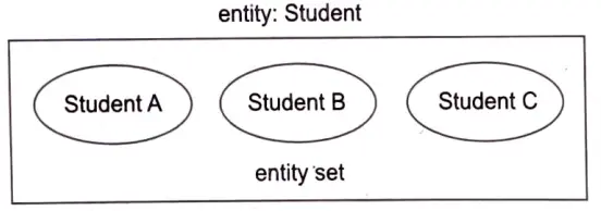
Entity Set: It is a set (or collection) of entities of the same type which share the similar properties or attributes.
For example, the group of people who are lecturers in a university can be defined as an entity set lecturer. Similarly, the entity set of students might represent the group of all students in the university.
An entity can be characterised into two types:
(i) Strong Entity: This type of entity has a primary key attribute which uniquely identifies each record in a table. In the ER diagram, a strong entity is usually represented by a single rectangle.
(ii) Weak Entity: An entity does not have a primary key attribute and depends on another strong entity via foreign key attribute. In the ER diagram, a weak entity is usually represented by a double rectangle.
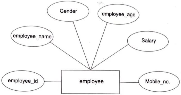
(b) Attributes: In an Entity-Relationship Model, an attribute represents the qualities or features of an entity. In the ER diagram, it is represented by an oval or ellipse form. Every oval shape symbolises one attribute and is directly related to its entity, which is shaped like a rectangle.
For example, employee_id, employee_name, Gender, employee_age, Salary and Mobile no. are the attributes which define entity type Employee.
In the ER model, an attribute can be characterised into the following types:
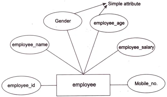
(i) Simple Attribute: An attribute which contains an atomic value and cannot be divided further is called a simple attribute. For example, Gender and Salary of a person. It is also represented by an oval.
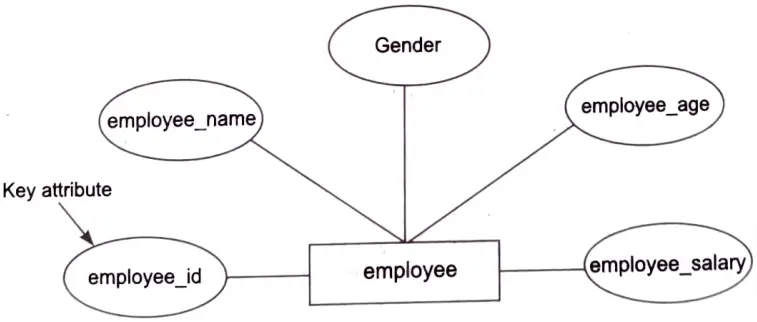
(ii) Key Attribute: A key attribute is an attribute that can uniquely identify an entity in an entity set. In the ER diagram, it represents a primary key. The key attribute in an Entity-Relationship diagram is represented by an ellipse with an underlying line. Employee_id, for example, will be unique for each employee.
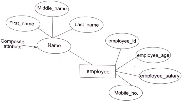
(iii) Composite Attribute: A composite attribute is an attribute that is made up of two or more simple attributes. It is represented by an ellipse in an Entity-Relationship diagram, and that ellipse is made up of additional ellipses. The Name attribute of an employee entity type, for example, comprises of the first name, middle name, and last name.
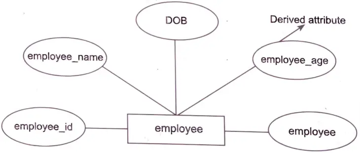
(iv) Derived Attribute: A derived attribute is one that may be derived from other attributes. These properties are represented by a dashed oval shape in an Entity-Relationship diagram. Employee _age, for example, is a derived attribute since it fluctuates over time and may be derived from another value, DOB (Date of birth).
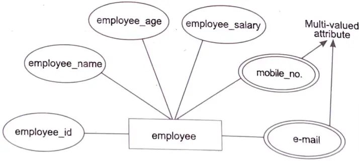
(v) Multi-valued Attribute: An attribute which contains more than one value for a given entity, For example, an employee can have more than one mobile number and email address.
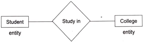
(c) Relationship: A relationship in Entity-Relationship Model is used to describe the relation between two or more entities. It is represented by a diamond shape in the ER diagram. For example, students study in college and employee works in a department.
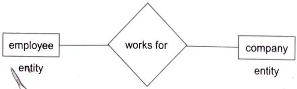
Here, works for is a relation between two entities.
Degree of Relationship: A relationship where a number of different entity set participate is called as degree of a relationship.
It can be categorised into the following types:
- (i) Unary Relationship: A relationship where a single entity set participates is called as a unary relationship.
- (ii) Binary Relationship: When two entity set participates in a relationship is called a binary relationship.
- (iii) Ternary Relationship: When three entity set participates in a relationship is called a ternary relationship.
- (iv) n-ary Relationship: When more than three entity set involves in a relationship is called an n-ary relationship.
13. Differentiate the following:
(i) Process and Project
Ans. Difference between Process and Project
| S. No. | Process | Project |
| 1. | A process has an objective that is often established around the process’s continuous functioning. | A project has an aim or conclusion that must be met, and the project concludes when that goal is met. |
| 2. | A process is generally ongoing and doesn’t normally have an end. | A project has a beginning and an end (albeit the beginning and end may not be well-defined when the project begins, and the conclusion may be many years away). |
| 3. | A process is a repeated sequence of tasks, and the tasks are known from the start because they are repetitive. | The sequence of tasks in a ‘project’ is not normally repetitive and may not be known at the outset of the project. |
(ii) LOC and FP
Ans. Difference between Line of Code (LOC) and Function Point (FP)
| S. No. | Line of Code (LOC) | Function Point (FP) |
| 1. | LOC metric is based on analogy. | FP metric is specification based. |
| 2. | LOC metric is design-oriented. | FP metric is user-oriented. |
| 3. | LOC metric is dependent on language. | FP metric is language independent. |
| 4. | It is changeable to FP, (i.e. back firing). | FP metric is extendible to Line of code. |
| 5. | LOC is used for calculating the size of the computer programme. | FP is used for data processing systems. |
| 6. | LOG is used for calculating and comparing the productivity of programmers. | FP can be used to portray the project time. |
(iii) Dynamic modelling and functional modelling.
Ans. Difference between Dynamic and Functional Modelling: The difference between dynamic modelling and functional modelling are as follows:
1. Concept: Dynamic modelling employs sequence and state diagrams to generate a collection of several state diagrams, with one state chart for each class exhibiting dynamic behaviour.
The functional model, on the other hand, gives an organised description of all of the system’s functions, with sequences leading to different states depicted on a single diagram rather than a collection of charts.
2. Performance of Operations: Dynamic model states when operations are performed, whereas the functional model states how operations are performed and which arguments are needed.
3. Function: The dynamic model will demonstrate how items interact with one another and change their ‘state’. A state is defined as a change in the values of an object. The dynamic model is concerned with the system’s dynamics and demonstrates how changes in object values are controlled. The dynamic model is concerned with the events that occur inside the system and how the variables of an item change as a result of these occurrences. Essentially, what we are representing here is what the ‘state’ of an item will be when an event occurs, which is why the dynamic model is also known as a ‘state transition diagram’. Each class in the dynamic model will have a state transition diagram.
The third and last component of the object modelling specification is the functional model. The functional model depicts the operations that occur within an item as well as how data changes as it flows between methods. The model will display the outcome of an action, but not the details of how the action is carried out. The functional model, like the object and dynamic models, is a visual representation of operations and data paths within the system.