
Table Of Contents
Explore the realm of Sensor and Transducers with the B.Tech AKTU Quantum Book. Access vital notes, repeated questions, and key knowledge for mastering this critical area. Unit-2 Sensors and Transducers-II
Dudes 🤔.. You want more useful details regarding this subject. Please keep in mind this as well.

Important Questions For Sensor and Transducers:
*Quantum              *B.tech-Syllabus
*Circulars               *B.tech AKTU RESULT
* Btech 3rd Year    * Aktu Solved Question Paper
Q1. Explain the construction and characteristics of thermistor.
Ans. A. Thermistor:
- 1. A thermistor (also known as a thermal resistor) is a type of resistor whose electrical resistance changes as the temperature changes.
- 2. A thermistor is highly sensitive to temperature fluctuations even though the resistance of all resistors will vary slightly with temperature.
- 3. Thermistors operate under the premise that resistance decreases as temperature rises.
- 4. The material used in thermistor is generally a semiconductor material such as a sintered metal oxide (mixtures of metal oxides, chromium, cobalt, iron, manganese and nickel) or doped polycrystalline ceramic containing barium titanate (BaTiO3) and other compounds.
- 5. As a semiconductor material’s temperature rises, more electrons are allowed to move about, which increases the amount of current flowing through it and lowers resistance.
- 6. Thermistors are robust and compact in size. They display nonlinear response traits.
- 7. Thermistors can be found as chips, probes, or beads (pressed discs). Fig. illustrates how a bead-type thermistor is built.
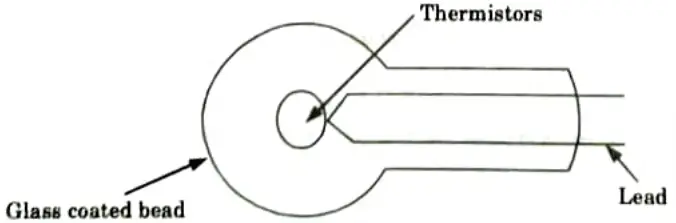
- 8. It has a tiny glass or ceramic bead that ranges in size from 0.5 mm to 5 mm. Two leads are used to join the bead to an electrical circuit.
- 9. The leads are housed in a stainless steel tube to protect them from the environment.
B. Thermistor characteristics:
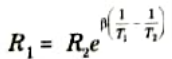
- 1. The relationship between temperature and resistance is given as :
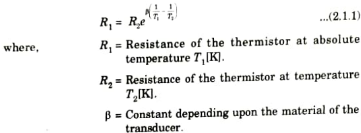
- 2. As we can see in the eq. (2.1.1) the relationship between temperature and resistance is highly nonlinear.
- 3. A standard NTC thermistor usually exhibits a negative thermal resistance temperature coefficient of about 0.05/°C.
Q2. Discuss the working principle of thermistor.
Ans. A. Working principle:
- 1. A thermistor’s resistance is temperature-dependent, which is how it functions. An ohmmeter can be used to determine a thermistor’s resistance.
- 2. Because there is a correlation between temperature and thermistor resistance, we may determine the thermistor’s temperature by measuring its resistance.
- 3. Change in resistance depends on the type of material used in the thermistor.
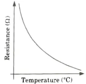
- 4. The relationship between a thermistor’s temperature and resistance is non-linear. A typical thermistor graph is shown in Fig.
B. Applications of thermistors:
- 1. To keep an eye on the engine’s coolant and/or oil temperatures.
- 2. To keep an incubator’s temperature under observation.
- 3. Contemporary digital thermostats employ thermocouples.
- 4. To track the temperature of battery packs when they are being charged.
- 5. To keep track of the 3D printers’ hot ends’ temperature.
- 6. To maintain the proper temperature in the machinery used in the food processing and handling industries.
- 7. To manage how common equipment like toasters, coffee machines, refrigerators, freezers, hair dryers, etc. operate.
Q3. How thermal imaging works ?
Ans.
- 1. Regardless of temperature, all objects radiate infrared energy (heat). The heat signature of an object is the infrared radiation it emits.
- 2. In general, an object emits more radiation the hotter it is. A thermal imager, commonly referred to as a thermal camera, is essentially a heat sensor that can pick up on even the smallest temperature variations.
- 3. The system gathers infrared radiation from nearby objects and builds an electronic representation of the area using data on temperature differences.
- 4. A thermal camera can detect items since they are rarely exactly the same temperature as objects around them, and they will appear as distinct in a thermal image.
- 5. You can see how much heat an object is radiating in relation to other objects by using thermal cameras, which essentially capture the temperature of different objects in the picture and then assign each temperature a shade of colour.
- 6. Thermal images typically have a grayscale character, with black things being cold and white objects being hot and changes between the two being indicated by the depth of the grey.
- 7. Yet, some thermal cameras add colour to photos to aid users in differentiating between things at various temperatures.
- 8. There are two common types of thermal-imaging devices:
- a. Un-cooled:
- i. The most popular kind of thermal imaging tool is this one. A unit that runs at room temperature houses the infrared detector components.
- ii. The battery is already included in this sort of device, which is entirely silent and instantly activates.
- b. Cryogenically cooled:
- i. These systems are more expensive and more prone to damage from rough use because the components are sealed inside a container that cools them to temperatures below 32 F (zero °C).
- ii. A benefit of such a system is the extraordinary sensitivity and resolution that come from cooling the components.
- iii. From a distance of more than 1,000 feet (300 metres), cryogenically-cooled devices can “see” a change as tiny as 0.2 F (0.1 °C).
Q4. What is Hall Effect sensor ? How it can be used to measure fluid level/position?
Ans. A. Hall Effect Sensor :
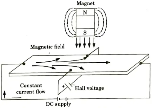
- 1. A Hall Effect sensor is a tool for gauging the strength of a magnetic field. The magnetic field intensity passing through it has a direct correlation with the output voltage.
- 2. A thin rectangular piece of p-type semiconductor material, such as Gallium Arsenide (GaAs), Indium Antimonide (InSb), or Indium Arsenide (InAs), that is conducting a steady current through itself is the basic building block of a hall effect sensor.
- 3. When the device is exposed to a magnetic field, the magnetic flux lines act as a force on the semiconductor material, deflecting the electrons and holes that carry charge to either side of the semiconductor slab.
- 4. The magnetic force that the charge carriers encounter as it passes through the semiconductor material is what causes them to move.
- 5. As these electrons and holes flow sideways, the accumulation of these charge carriers creates a potential difference between the two sides of the semiconductor material.
- 6. Next, the presence of an external magnetic field that is perpendicular to it has an impact on how electrons pass through semiconductor materials; this impact is stronger for materials with flat, rectangular shapes.
- 7. Fig. illustrates the Hall Effect sensor’s basic operation. The idea behind how Hall Effect sensors operate is that when a beam of charged particles passes through a magnetic field, forces are exerted on the particles, causing the beam to be deflected from its intended path.
- 8. The disc will then have a negative charge on one side and a positive charge on the other.
- 9. This charge separation produces a potential difference, which is a measurement of the magnetic field’s separation from the current-carrying disc.
B. Hall effect sensor to measure the fluid level in a container:
- 1. The measuring of fluid level in a container is the typical application of a Hall Effect sensor.
- 2. The structure of the container is a float with a permanent magnet fastened to the top. The shell is mounted with an electrical circuit and a current-carrying disc.
- 3. The magnet will approach the disc as the fluid level rises, creating a potential difference. This voltage activates a valve that shuts off the flow of fluid into the container.
- 4. These sensors are used to determine an object’s location and measure displacement. The requisite signal conditioning circuitry is required for Hall Effect sensors.
- 5. They can be operated at 100 kHz. Their non-contact nature of operation, good immunity to environment contaminants and ability to sustain in severe conditions make them quite popular in industrial automation.
Q4. Discuss capacitive proximity sensors.
Ans.
- 1. Both metallic and non-metallic objects in powder, granulate, liquid, and solid form can be detected using capacitive proximity sensors.
- 2. This makes them perfect for sight glass monitoring, tank liquid level detection, and hopper powder level recognition. They can even sense through nonferrous materials.
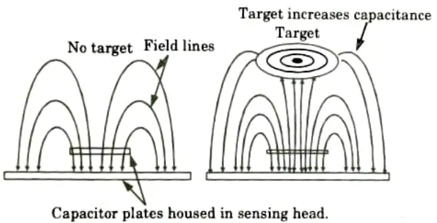
- 3. In capacitive sensors, the two conduction plates are housed in the sensing head and positioned to function like an open capacitor. These plates are at different potentials.
- 4. Because air is an insulator, there is not much capacitance between the two plates while they are at rest. These plates have connections to an oscillator, a Schmitt trigger, and an output amplifier just like inductive sensors do.
- 5. The capacitance of the two plates increases as a target moves into the detecting zone, changing the oscillator’s amplitude, the Schmitt trigger state, and the output signal.
Q5. How do we measure vibration with the help of proximity sensors ?
Ans.
- 1. There are three main categories of vibration sensors: displacement, velocity, and acceleration.
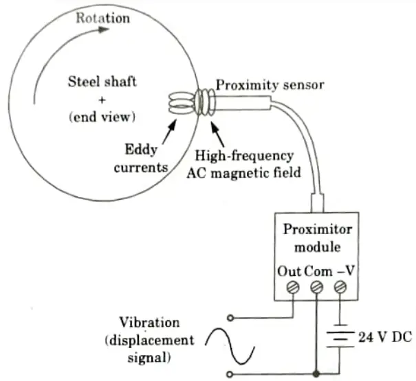
- 2. To measure the separation between the probe tip and the revolving machine shaft, these sensors employ electromagnetic eddy current technology.
- 3. The sensor itself is a wire coil that has been enclosed and is powered by high frequency alternating current (AC).
- 4 The magnetic field generated by the coil creates eddy currents in the machine’s metal shaft, as if the metal shaft were a transformer’s secondary coil that had been short-circuited (with the probe’s coil serving as the transformer’s primary winding).
- 5. The magnetic connection between the shaft and the sensor coil is tighter and the eddy currents are stronger the closer the shaft advances towards the sensor tip.
- 6. The induced eddy currents load the high-frequency oscillator circuit that generates the excitation signal for the sensor coil.
- 7. As a result, the oscillator’s load may now be used to determine precisely how near the metal shaft the probe tip is.
- 8. Measuring the proximity of a wire coil to any metal object by the amount of loading brought on by eddy current induction is similar to how a metal detector works.
- 9. The oscillator circuit that excite the sensor coil in this configuration is known as a proximitor.
- 10. A coaxial cable is used to drive the sensor coil through the proximitor module, which is powered by an external DC power source.
- 11. A DC voltage output from the proximitor module serves as a representation of proximity to the metal shaft.
- 12. A “silent” signal (with no vibration) will be a pure DC voltage because the proximitor’s output voltage is a direct representation of the distance between the probe’s tip and the shaft’s surface.
- 13. A technician sets the probe so that the quiescent voltage falls between the proximitor’s output voltage range boundaries.
- 14. The output voltage of the proximitor will change in a precise step whenever the shaft vibrates.
- 15. Shaft vibration as detected in the probe’s axis will be directly represented on an oscilloscope when connected to this output signal.
Q6. Discuss the working of laser (or optical) flow sensor.
Ans.
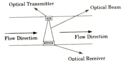
- 1. Using the optics concept, laser (or optical) flow sensors use light to measure the flow rate.
- 2. Typically, they use a system that consists of photodetectors and a laser beam.
- 3. In this situation, the laser beam is scattered by the gas passing through the pipe, creating pulses that are detected by the receiver as illustrated in Fig.
- 4. If the separation between the photo-detectors is known, the time between these signals can be calculated, which allows for the calculation of the gas’s speed.
- 5. These metres are unaffected by changes in gas flow or heat conditions since they detect the actual speed of the gas-forming particles.
- 6. They can therefore provide extremely accurate flow data even in the most challenging conditions.

Sensor and Transducers Btech Quantum PDF, Syllabus, Important Questions
| Label | Link |
|---|---|
| Subject Syllabus | Syllabus |
| Short Questions | Short-question |
| Question paper – 2021-22 | 2021-22 |
Sensor and Transducers Quantum PDF | AKTU Quantum PDF:
| Quantum Series | Links |
| Quantum -2022-23 | 2022-23 |
AKTU Important Links | Btech Syllabus
| Link Name | Links |
|---|---|
| Btech AKTU Circulars | Links |
| Btech AKTU Syllabus | Links |
| Btech AKTU Student Dashboard | Student Dashboard |
| AKTU RESULT (One VIew) | Student Result |