
Table Of Contents
B.Tech AKTU Quantum Book will take you on a journey through the world of Sensor and Transducers. Access important notes, frequently asked questions, and valuable information for learning this fundamental area. Unit-1 Sensors and Transducers-I
Dudes 🤔.. You want more useful details regarding this subject. Please keep in mind this as well.

Important Questions For Sensor and Transducers:
*Quantum              *B.tech-Syllabus
*Circulars               *B.tech AKTU RESULT
* Btech 3rd Year    * Aktu Solved Question Paper
Q1. Define sensor and transducer with a common example.
Ans. A. Sensor:
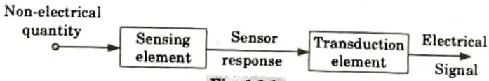
- 1. It is described as a component that generates a signal related to the amount being measured in paragraph one.
- 2. It can also be described as “A device that produces a usable output in response to a designated measurand” in definition number two.
B. Transducer:
- 1. It is described as an element that, when subjected to a physical change, experiences a related change or as an element that, using the transduction principle, transforms a given measurand into a useful output.
- 2. Another definition of it is a machine that changes a signal from one kind of energy to another.
C. Example:
- 1. A copper-nickel alloy wire can be referred to as a sensor because variations in mechanical displacement (tension or compression) can be detected as changes in electric resistance.
- 2. When proper electrodes and an input-output mechanism are coupled to this wire, it functions as a transducer. We can therefore state that “sensors are transducers.”
Q2. Classify transducers.
Ans.
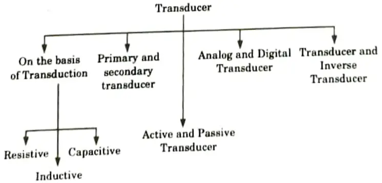
- A. Classification based on the principle of transduction :
- i. The transduction medium categorizes the transducer.
- ii. Depending on how the input transducer converts the input signal into resistance, inductance, or capacitance, the transduction medium may be resistive, inductive, or capacitive.
- B. Primary and secondary transducer:
- a. Primary transducer:
- i. The transducer is made up of both mechanical and electrical components.
- ii. The mechanical components of the transducer convert the mechanical signal from the physical input quantities. The primary transducers are the technical name for this apparatus.
- b. Secondary transducer:
- i. The mechanical signal is changed into an electrical signal by the secondary transducer.
- ii. The mechanical signal’s input affects the output signal’s strength.
- a. Primary transducer:
- C. Passive and active transducer :
- a. Passive transducer:
- i. A passive transducer is one that draws its power from a source outside of the device.
- ii. They are additionally referred to as external power transducers.
- iii. Examples of passive transducers include capacitive, resistive, and inductive transducers.
- b. Active transducer:
- The term “active transducer” refers to a transducer that does not require an external power source.
- ii. This kind of transducer is a self-generating transducer because it generates its own voltage or current.
- iii The physical input quantity is used to generate the output signal.
- a. Passive transducer:
- D. Analog and digital transducer:
- a. Analog transducer:
- i. The input quantity is converted into a continuous function by the analogue transducer.
- ii. Examples of analogue transducers include the thermocouple, strain gauge, LVDI, and thermistor.
- b. Digital transducer: These transducers transform an input quantity into a pulse or a digital signal. Both high and low power digital signals are functional.
- a. Analog transducer:
- E. Transducer and inverse transducer:
- a. Transducer: The transducer is the apparatus that transforms a non-electrical quantity into an electric amount.
- b. Inverse transducer: The term “inverse transducer” refers to a transducer that transforms an electric quantity into a physical quantity. High electrical input and low non-electrical output characterize the transducer.
Q3. What are the various advantages of transducers ?
Ans.
- 1. A static transducer device makes it simple to amplify and attenuate electrical signals.
- 2. The electrical systems do not contain any mechanical moving parts. Hence, there is no concern about mechanical deterioration and no chance of mechanical failure.
- 3. A very small amount of electric power can be used to control an electric or electronic system.
- 4. It is simple to process (primarily amplifying) and bring an electrical signal from an electrical transducer to a level that is appropriate for an output device, such as an indicator or recorder.
- 5. With the advent of IC technology, the electronic systems have become extremely small in size, requiring small space for their operation.
Q4. What are the advantages and disadvantages of LVDT transducers ?
Ans. A. Advantages:
- 1. High output and high sensitivity: The LVDT gives a high output and a high sensitivity.
- 2. Ruggedness: Especially when the core is spring loaded, these transducers can typically withstand high levels of shock and vibration without experiencing any negative effects.
- 3. Low hysteresis: LVDTs show a low hysteresis and hence repeatability is excellent under all conditions.
- 4. Low power consumption: Most of LVDTs consume power which is less than 1W.
B. Disadvantages:
- 1. Appreciable differential output requires relatively large displacements.
- 2. Although shielding is an option, they are sensitive to stray magnetic fields. This is accomplished by including longitudinal slots in magnetic shields.
- 3. Vibrations frequently have an impact on the performance of the transducer.
- 4. If a DC output is required, the receiving device must be set to operate on AC signals, or a demodulator network must be used.
- 5. The mass of the core limits the dynamic response mechanically, and the frequency of the applied voltage limits it electrically.
Q5. Explain the construction and working of optical encoder for displacement measurement with suitable diagram.
Ans.
- 1. A digital electrical output of an optical encoder is proportional to the angular position of the input shaft. It is an electromechanical device.
- 2. Using optical encoders, it is possible to convert an angular displacement directly into a digital format. An angular position sensor is an optical encoder.
- 3. A disc is rigidly fixed to it and rotated by a shaft that is mechanically connected to an input driver.
- 4. The transparent slits of the rotating disc allow the infrared emitting diodes’ light to pass through to the infrared receivers.
- 5. The signal is then electronically amplified and digitally transformed after that. After that transmission, this signal is received by the data processor.
- 6. It has a disc with three concentric tracks of holes that are evenly spaced apart.
- 7. To detect the light passing through the holes, three light sensors are used.
- 8. These sensors generate electric pulses that, when applied to a mechanical component, such as a shaft, measure the angular displacement of the optical encoder.
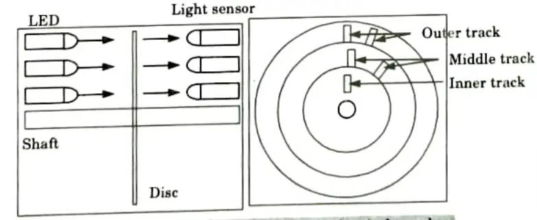
- 9. To determine the disc’s “home” position, there is just one hole in the inner track. Half of the hole’s width separates the holes on the middle track from those on the outside track. This configuration makes it possible to determine the rotation’s direction.
- 10. When the disc rotates clockwise, the pulses on the outside track move ahead of those on the inner track; when it rotates anticlockwise, they move behind.
- 11. The resolution can be determined by the number of holes on disc. With 100 holes in one revolution, the resolution would be,
360°/100 = 3.6°
Q6. Discuss piezoelectric sensor or transducer with suitable diagram.
Ans.
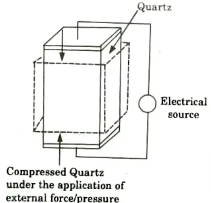
- 1. A device that utilizes the piezoelectric effect to monitor changes in acceleration, pressure, strain, temperature, or force by turning this energy into an electrical charge is known as a piezoelectric transducer (also known as a piezoelectric sensor).
- 2. A crystal is elastically bent when pressure is applied. This deformation causes an electric charge to flow (which lasts for a period of a few seconds).
- 3. The electric signal that is produced can be measured to determine the pressure that was applied to the crystal.
- 4. These sensors are employed to measure quickly changing pressures brought on by blasts, explosions, pressure pulsations (from rocket motors, engines, compressors), or other causes of shock or vibration. They are unable to detect static pressures.
- 5. Piezoelectric sensors are used to measure dynamic forces such oscillation, impact, and high-speed compression or tension as well as pressure, acceleration, and these forces.
- 6. It includes piezoelectric ionic crystal components like Quartz, as depicted in Fig. These materials stretch or contract when pressure or force is applied.
- 7. The charge over the substance shifts and redistributes during this operation. The material’s faces become positively and negatively charged, respectively.
- 8. The net charge q on the surface is proportional to the amount x by which the charges have been displaced. The displacement is proportional to force. Therefore we can write,


Sensor and Transducers Btech Quantum PDF, Syllabus, Important Questions
| Label | Link |
|---|---|
| Subject Syllabus | Syllabus |
| Short Questions | Short-question |
| Question paper – 2021-22 | 2021-22 |
Sensor and Transducers Quantum PDF | AKTU Quantum PDF:
| Quantum Series | Links |
| Quantum -2022-23 | 2022-23 |
AKTU Important Links | Btech Syllabus
| Link Name | Links |
|---|---|
| Btech AKTU Circulars | Links |
| Btech AKTU Syllabus | Links |
| Btech AKTU Student Dashboard | Student Dashboard |
| AKTU RESULT (One VIew) | Student Result |