With AKTU’s Question Paper, you may embark on an Exciting Railways, Water & Airport Engineering Journey. Improve your understanding, test your knowledge, and fly to exam achievement.
Dudes 🤔.. You want more useful details regarding this subject. Please keep in mind this as well.

Important Questions For Railways, Waterway and Airport Engineering:
*Quantum          *B.tech-Syllabus
*Circulars           *B.tech AKTU RESULT
* Btech 4th Year
Section A: Short Question In Railways, Water & Airport Engineering
a. Define the route of Group A lines.
Ans. Route of Group A Lines: These lines are meant for a sanctioned speed of 160 km/h :
- 1. New Delhi to Howrah by Rajdhani route.
- 2. New Delhi to Mumbai Central by Frontier Mail Rajdhani route.
- 3. New Delhi to Chennai Central by Grand Trunk route.
- 4. Howrah to Mumbai VT via Nagpur.
b. What are spikes ?
Ans. Spikes are used to attach rails to the wooden sleepers. Spikes of various varieties are widely used to hold hat footed rails.
c. Define formation in track.
Ans. Formation refers to the prepared surface that is ready to receive ballast. The track’s stability is determined by the condition of the formation beneath it.
d. Write treated and untreated wooden sleepers.
Ans. The committee recommended that for simplification and rationalization, wooden sleepers should be classified in two categories :
- a. ‘U’ or Untreated sleepers comprising of all the sleepers made of wood from naturally durable species.
- b. ‘T’ or Treated sleepers consisting of the rest of the sleepers.
e. Define caution indicators.
Ans. As the track is being repaired, the driver should slow down and be prepared to stop at any time.
f. What do you understand by high speed track ?
Ans. A track on which the speed of running train is 120 kmph or more is considered as a high speed track.
g. Define Jet blast.
Ans. Jet blast is the phenomena of rapid air movement caused by aircraft jet engines, typically before or before takeoff.
A large jet-engined aircraft can produce winds of up to 100 knots (190 km/h; 120 mph) as far away as 60 metres (200 ft) behind it at 40% maximum rated power.
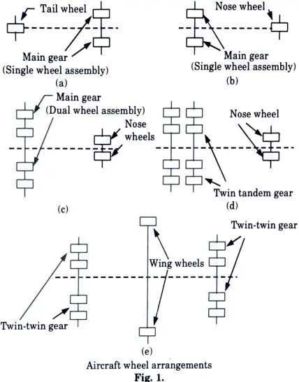
h. What are wheel arrangement in aircraft ?
Ans. The wheel arrangement in aircraft are shown in Fig. 1.
i. Define Harbour of Refuge ?
Ans. Harbours of Refuge: Large harbours that are beneficial for sheltering ships during emergency scenarios such as storms or other natural calamities. Refugee harbours are built with broad entrances and are easily accessible. They provide safe anchorage for vessels during storms and tides.
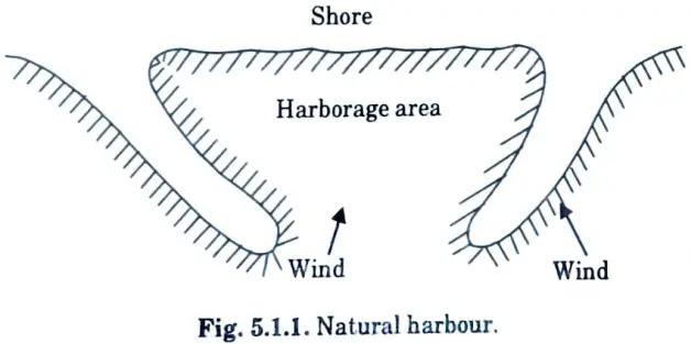
j. Draw neat sketch of natural harbour.
Ans.
Section B : Aktu Long Questions of Railways, Water & Airport Engineering
a. Discuss the merits and demerits of diesel and electric traction.
Ans. Merits of Diesel Traction :
- 1. It has a lower initial cost than an electric train because it does not require power substations, distribution lines, and feeders, among other things.
- 2. Because of its fast acceleration and brake deceleration, it has a higher scheduled speed than a steam locomotive.
- 3. The torque exerted by this traction system is greater than that of a steam engine. As a result, more coaches can be installed.
- 4. This requires less maintenance and repair time than a steam locomotive.
- 5. Its efficiency is 25% higher than that of a steam locomotive.
- 6. There is no power loss during speed control.
Demerits of Diesel Traction :
- 1. Diesel engine has a short life span.
- 2. Limited overloading capacity.
- 3. Diesel engines and motor-generator combinations require a separate cooling system.
- 4. The operating and maintenance costs are extremely high.
- 5. Because of the motor-generator set and other accessories, the engine’s load increases, necessitating the use of extra axles.
- 6. The price of fuel (diesel) is high, and the country’s economy is suffering as a result of the rapid price fluctuation.
Merits of Electric Traction :
- 1. There is no need to store water and coal.
- 2. It does not contaminate the atmosphere.
- 3. Electrical connecting system is neat and clean.
- 4. Its maintenance can be done easily.
- 5. High acceleration and retardation values can be obtained.
- 6. In electric traction, demerits the value of initial torque is high.
- 7. Electrical insulation is better than another braking.
Demerits of Electric Traction :
- 1. Because the installation cost of electric traction is considerable, more money is required at the start.
- 2. When the electricity is turned off, rail traffic is impeded.
- 3. Interference is generated in the communication cables that run parallel to the power lines. To avoid this, either the phone lines are disconnected or costlier cables are used.
- 4. Room heating is done cheaply in steam locomotives during the winter, but additional equipment is required with electric locomotives.
b. Two high-level platforms are to be provided on the inside as well as the outside of a 2° curve on a BG track with a super elevation of 100 mm. What should be the required extra clearances for these platforms, both on the inside and outside of the curve, Length of bogie = 21, 340 mm, c/c bogie distance = 14, 785 mm, height of platform = 840 mm.
Ans. Given: Degree of curve, D = 2°, Super elevation, e = 100 mm, Length of bogie, L = 21340 mm, dc bogie distance, c = 14785 mm, Height of platform, h = 840 mm
To Find: Extra clearance.
2. Extra clearance requires on the inside of the curve,
Ec1 = Overthrow + lean + sway – 51 mm
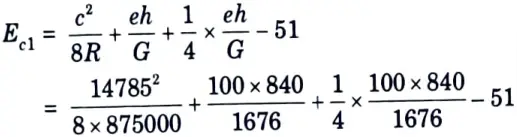
= 42.877 mm = 45 mm
3. Extra clearance required on the outside of the curve,
Ec2 = End throw – 25 mm
= 8.83 mm = 10 mm
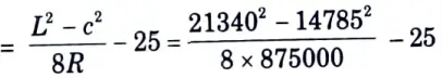
c. Briefly describe the absolute block system of controlling the movements of trains for single and double lines.
Ans. 1. Absolute Block System or Space Interval System (or Lock and Block System) :
- i. With this system, the entire track is divided into sections known as block sections, which are separated by block stations, which are stations equipped with block instruments in pairs at each station.
- ii. These devices indicate whether the section ahead is clear or reserved for a train.
- iii. All block-sections are linked in series, both telegraphically for block instrument operation and telephonically for information exchange.
- iv. The station master is in command of a block station, and two neighbouring block stations are in charge of a block section.
2. The following are the essentials of the absolute block system :
- i. No train should depart a block station unless authorization has been obtained in advance from the block station, i.e., receiving station. This is required for train dispatching.
- ii. No train should be given permission to approach a block station unless :
- a. When the line on which the train is being run is clear up to an acceptable distance beyond the first stop signal at the station where permission is being granted.
- b. In the case of a single line, when the line is clear up to an adequate distance beyond the first stop signal and is clear of trains running in the opposite direction or will be clear of trains after the complete arrival of the train heading towards the station to which the permission is being granted. These are required for train reception.
- iii. When two trains are running on the same line and in the same direction, the permission to approach for the second train should not be given unless :
- a. The first train has arrived at its proper position within the home.
- b. All the signals behind the first train have been put back to ON positions.
- c. The line is clear not just up to the station’s first stop signal, but also for a sufficient distance beyond it.
- d. For the second train, all switches or points have been placed, facing points locked, and trailing points bolted. These are the fundamentals of conditional line clearing.
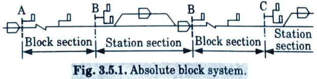
d. Explain with neat sketches, various marking on a run way.
Ans. Types of Runway Marking: Following are the markings made on the runways :
1. Runway Centre Line Marking: The centre line of the runway is represented by a broken strip running along the entire length of the runway as shown in Fig. 4.18.1. Its width is 90 cm.
2. Runway Edge Stripes: The runway edges are normally marked. But when the width of runway exceeds 45 m, the side stripes in the form of long continuous line 90 cm wide may be marked near the edges as shown in Fig. 4. 18.1 and Fig. 4.18.4.
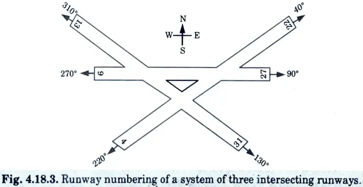
3. Runway Numbering :
i. Each runway’s end is marked with a number that represents the magnetic azimuth, or the angle measured in a clockwise direction of landing. As seen in Fig. 4.18.2, the east end of an east-west runway would be marked 27 (for 270°) and the west end 9 (for 90°).
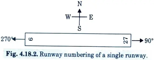
ii. If there are more than three parallel runways, one pair is marked with the magnetic azimuth to the nearest 10° and the other pair with the magnetic azimuth to the next closest 10°.
iii. For example, if there are four runways, one pair would be designated as 9-27 and the other as 8-26 or 10-28.
iv. Fig. 4.18.3 shows the runway numbering of a system of three intersecting runways.
4. Touch Down or Landing Zone: The runway touch down or landing zone is denoted by a series of stripes grouped symmetrically about the centre line, with the number decreasing gradually in the direction of landing, as shown in Fig. 4.18.1.
5. Threshold Marking :
i. The runway threshold is indicated by series of parallel lines starting from a distance of 6 m from the runway end as shown in Fig. 4. 18.4.
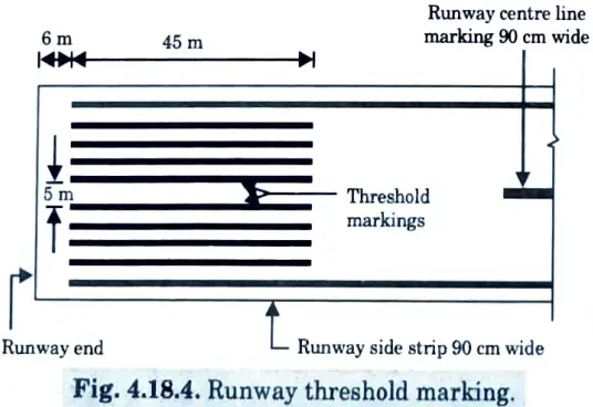
ii. The threshold marks are 3.60 m broad, 0.90 m clear, and symmetrically placed on either side of the runway centre line.
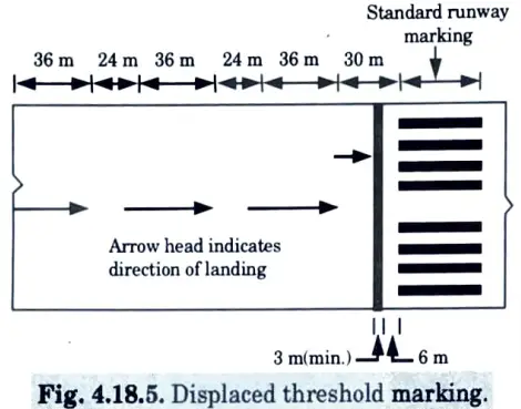
iii. For some airports, it is preferable to permanently relocate the runway threshold.
iv. A misplaced threshold is one that has been shifted a set distance from the runway’s end.
v. It is usually adapted to clear obstructions in the flight path.
vi. The displacement however reduces the length of the runway for landings, but take offs can use the entire length of the runway.
vii. The FAA requires that the displaced threshold should be marked as shown in Fig. 4.18.5.
6. Two or More Parallel Runways: When there is more than one runway in the same direction, the following letters are added to the azimuth numbers :
Two parallel runways – L, R
Three parallel runways- L, C, R
Four parallel runways -L, R, L, R
Five parallel runways – L, C, R, L, R.
e. Give the advantages and disadvantages of direct labour method.
Ans. Direct Labour Method :
- 1. Advantages: Following are the advantages of direct labour method :
- i. It is possible to create a large-scale coordinated plan for the entire country.
- ii. It is possible to make better use of the existing plant. This strategy is also useful for satisfying urgent needs at any time.
- iii. This technique eliminates the potential for disagreements when the completed dredging works are measured and checked.
- iv. This system also avoids the general costs of contractors due to longer depreciation terms.
- 2. Disadvantages: Following are the disadvantages of direct labour method :
- i. It lacks flexibility.
- ii. It needs important administrative direction.
- iii. It is difficult to pay the personnel in accordance with the work. Hence working personnel exhibit lack of interest.
- iv. It is experienced to frequent negligence of maintenance.
Section 3 : Coach Screw
a. With neat sketches explain Coach Screw of rail screw and Elastic spikes.
Ans. 1. Screw Spikes (or Coach Screw of Rail Screw) :
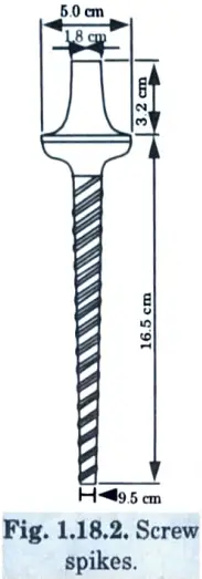
- i. These are tapered screws with V-threads that are used to secure rails to timber sleepers. The round head has a square projection. Fig. 1.18.2.
- ii. Screw spikes have more than twice the gripping strength of dog spikes and can withstand lateral thrust better than dog spikes.
- iii. However, screw spikes are expensive, and their usage makes gauge maintenance more complex, hence dog spikes are favoured over screw spikes.
2. Elastic Spikes :
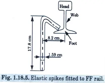
- i. When we utilise dog spikes, the downside is that owing to rail wave motion, the dog spikes come out of the sleepers and allow creep to occur. Elastic spikes are employed to solve this problem.
- ii. Its spike’s advantage is that its head absorbs wave motion without becoming loose.
- iii. These spikes provide superior grip and reduce rail wear and tear as well as creep. It is depicted in Fig. 1.18.5.
b. Using a sleeper density of N + 5 find out the number of sleepers required for constructing a railway track (BG) 1000 m long.
Ans. Given: Sleeper density = N + 5, Length = 1000 m.
To Find: Number of sleeper in 1000 length.
1. Length of each rail on a BG track = 12.8 ≈ 13m
3. Sleeper density = N + 5
4. Number of sleeperS under each rail = 13 + 5 = 18
5. Total numbers of sleeper required = 77 x 18 = 1386 sleepers.
Section 4 : Important Numerical
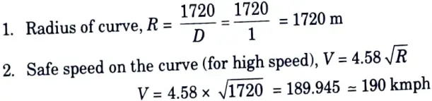
a. The wheel base of a vehicle moving on a BG track is 6 m. The diameter of the wheels is 1524 mm and the flanges project 32 mm below the top of the rail. Determine the extra width of the gauge required if the radius of the curve is 168 m. Also indicates the extra width of gauge actually provided as per Indian Railways Standards.
Ans. Given: Wheel base = 6 m, Diameter of wheel, D = 1524 mm, Flange projection, h = 32 mm, Radius of curve, R = 168 m
To Find: Extra width of the gauge, Actual extra width as per IR standards.
2. Extra width of gauge is given by,
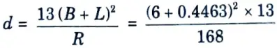
d = 3.2155 cm = 32.155 mm
3. As per Indian railways standards, an extra width of 10 mm is provided for curve with a radius less than 350 m in actual practice.
b. Calculate the maximum permissible speed on a 1° curve on a Rajdhani route with a maximum sanctioned speed of 130 km hr. The superelevation provided is 50 mm and the transition length is 60 m. The transition length of curves cannot be increased to the proximity of the yard.
Ans. Given: Degree of curve, D = 1, Maximum sanctioned speed = 30 kmph, Super elevation, e = 50 mm, Transition length, L = 60 m
3. Speed from super elevation consideration :
- i. Actual super elevation = 50 mm
- ii. Maximum cant deficiency for high speed track = 10 cm = 100 mm
- iii. Theoretical super elevation = 50 + 100 = 150 mm
- iv. Equilibrium speed for this super elevation.
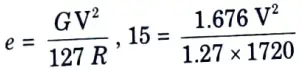
V = 139.82 = 140 kmph
4. Speed from length of transition curve :
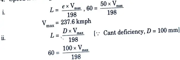
Vmax = 118.8 kmph
5. The maximum permissible speed on the curve is minimum of the above speed, that is, 118.8 kmph.
Section 5 : Functions of Interlocking
a. Explain the principle and functions of interlocking.
Ans. A. Principle of Interlocking: Following are the various principles of interlocking :
- 1. It shall not be possible to take OFF conflicting signals at one and the same time.
- 2. It shall not be possible to take OFF signal for the running line until :
- a. All running line points are accurately established and facing points are secured.
- b. All points connecting the sidings and goods lines to the running line are located against the running line.
- c. Level crossing gates are locked across the roadway if included or controlled by interlocking.
- d. A signal lever that is drawn must lock or rear lock the levers that operate the points and gate locks mentioned above.
- 3. When all signals are in the ON position, all points which would be locked by taking OFF such signals must be free for shunting purposes.
- 4. It must be impossible to take OFF a warner signal, until all the relative stop signals in advance have first been taken OFF and when OFF it must back lock all such signals.
B. Functions of Interlocking: Following are the functions of interlocking :
- 1. It must be impossible to turn OFF a signal for an incoming train unless the route (including the over-lap) is properly established, locked, and held. This means that the points must be set and each facing point secured such that it finds the train’s passage and can withstand the strains caused by the train at the divergence junction. At the same time, it must be impossible to operate the points (i.e., unlock or reverse the points) while the train is travelling on it; otherwise, the train may take contradictory courses.
- 2. It must be impossible to take the OFF position for two fixed signals at the same time, as this would result in conflicting movements (i.e., motions that cross each other’s path). As a result, the points and signals should be linked to prevent such movements.
- 3. Loose waggons must not be able to interfere with the path for which the points have been set and the signal has been turned OFF. To do this, levers, operating points, and signals must be interconnected in such a way that they can only be pulled in a specific sequence or order, and likewise returned in a specific sequence (i.e., reverse sequence or order).
- 4. The route, for which the points are set and signal taken to OFF position, should be clear of any obstructions.
b. Discuss about the following :
i. Linear motion, and
ii. Tracked Air Cushion Vehicle.
Ans. i. Linear motion :
- 1. The linear induction motor has nearly limitless potential for achieving extremely high speeds.
- 2. It can be created from a rotating induction motor by cutting and unrolling both the primary and secondary members and then considerably expanding the length of one of the unrolled parts.
- 3. Because the thrust is created without physical touch, the motor is compatible with all types of guidance and suspension systems, including air cushion.
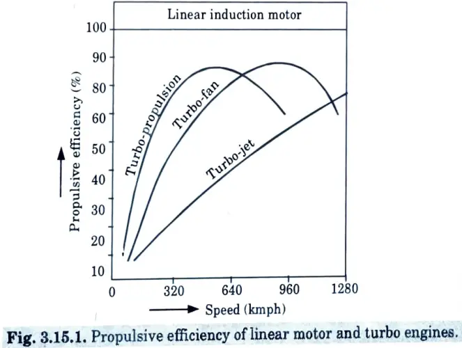
- 4. Fig. 3.15.1 shows a graph of the propulsive efficiency for various speeds of linear motor and turbo engines. A traction system such as linear motor, which is free from adhesion, on a very wide track gauge, may enable to attain a speed of 350 kmph.
ii. Tracked Air Cushion Vehicle :
- i. In 1969, Britain produced a vehicle capable of carrying 80 passengers at speeds of up to 300 km/h and driven by a 2.3 m diameter air screw powered by two 1200 HP gas turbines.
- ii. The vehicle was supported by eight air cushions, four on each side, and was directed by six more air cushions bearing against the central vehicle component of the concrete guide path.
Section 6 : Airport Capacity
a. What do you understand by the term airport capacity ? What are the factors which affect the airport capacity ?
Ans. 1. Airport Capacity: The term airport capacity refers to the number of aircraft movements that an airport may handle in a given period of time while allowing for an acceptable duration of delay for leaving aircraft.
2. Factor: Following are the affecting factors of airport capacity :
- i. Arrangement, size and number of gates in the apron area.
- ii. Availability and structure of the air-space for establishing the arrival and departure routes.
- iii. Characteristics of the aircrafts using the airport.
- iv. Configuration, number and location of the taxiways and runway exits.
- v. Configuration, number, spacing and orientation of the runway system.
- vi. Existence and nature of the navigational aids.
- vii. Nature and extent of the air-traffic control facilities.
- viii. Number of arrivals relative to the number of departures.
- ix. Runway occupancy time for arriving and departing aircraft.
- x. Techniques adopted by the controller to operate the runway system.
b. What are the different design methods that is followed for Airfield pavement design ? Explain.
Ans. A. Design of Flexible Pavement :
- 1. The flexible pavement design is mostly based on the empirical CBR approach.
- 2. Using the CBR approach, the designer can determine the needed thickness of the sub-base, base, and surface course by inputting a series of design curves based on the results of a relatively easy soil test.
- 3. The CBR test is an empirical standardised test that expresses an index of the shearing strength of the soil.
- 4. The subgrade has been appropriately compacted and may have a CBR value of 5 to 10%. 5. A layer of sub-base with a CBR value of 20 to 50% is put over the compacted subgrade.
- 5. Over the sub-base is laid a layer of base having CBR value of80 to 90 %.
- 6. On the top of the base is put the bituminous surfacing of 5 to 10 cm thick laid in two layers.
- 7. The empirical relationships in the form of charts and curves for various wheel loads have been established between the CBR test value and the thickness of the pavement structure. The procedure adopted is as follows :
- i. For a specific design load, the total thickness of pavement (sub-base, base, and surfacing) is calculated for the equivalent CBR (California Bearing Ratio) value of the subgrade.
- ii. Similarly, the thickness of pavement consisting of base and surfacing is calculated for the given design load and associated CBR of sub-base.
- iii. Lastly, the thickness of pavement, i.e., surfacing, is calculated for the specified design load and associated CBR of base.
B. Design of Rigid Pavements: Following are the three recognized methods available for the design of rigid pavements :
- 1. FAA method.
- 2. Method based on Westergaard’s analysis.
- 3. PCA method.
1. FAA Method :
- i. As in case of the flexible pavements, the FAA has prepared charts for the determination of slab thickness under different conditions of the subgrade soil.
- ii. The thicknesses of the surface and subgrade can be obtained directly by referring to these charts.
2. Method based on Westergaard’s Analysis :
- i. A rigid pavement slab resists deflection not only because of the subgrade reaction but also because of its own stiffness.
- ii. The stress equations developed by Westergaard are as follows :
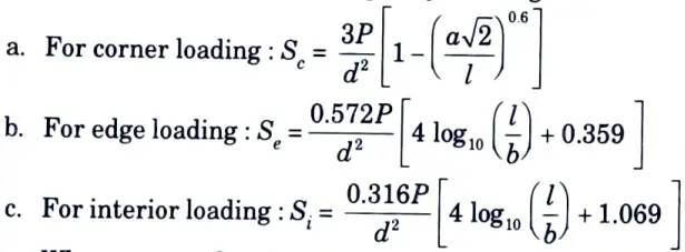
Where, Sc = Maximum stress at corner in kg/cm2.
Se = Maximum stress at edge in kg/cm2.
Si = Maximum stress at interior in kg/cm2.
P = Wheel load in kg.
d = Slab thickness in cm.
a = Radius of wheel distribution in cm.
l = Radius of relative stiffness in cm.
b = Radius of resisting section in cm.
Note : If ‘a’ is greater than 1.724 d, the value of ‘b’ is to be taken as equal to ‘a’
3. PCA Method :
- i. The influence charts are developed by Portland Cement Association (PCA) ofU.S.A. using the basic equations of Westergaard.
- ii. The use of these charts considerably saves the time for making the design calculations.
- ii. To obtain the allowable stress, the PCA has recommended to adopt the factors of safety as mentioned in table 1.
Table 1: Recommended Factors of Safety By PCA
| S. No. | Location | Safety factor |
| 1. | Aprons, taxiways and runway ends | 1.7 to 2.0 |
| 2. | Runways (central portion) | 1.4 to 1.7 |
C. LCN Method of Pavement Design :
- 1. The supporting capacity of a pavement is expressed in terms of a number known as LCN in this manner. Similarly, the ESWL (equivalent single wheel load) of any ship can be described in terms of LCN depending on the composition and thickness of the pavement, gear shape, and pressure.
- 2. If the LCN of an aircraft pavement is greater than the LCN of the aircraft, the aircraft can use the pavement safely.
- 3. The concept of a standard load classification curve was established in order to indicate the capacity of pavement as a single number.
i. LCN for Flexible Pavement :
- a. To obtain the LCN of a flexible pavement, the repetitive plate bearing tests are carried out on the existing airport pavement.
- b. The safe load for a pavement is that load which when applied 10000 times produces 5 mm deflection.
- c. The contact area of the plate is taken equivalent to the contact area of one main wheel of the aircraft.
- d. For civil airports, the plate of 46 cm diameter with contact area of 1652 cm2 is generally used.
ii. LCN for Rigid Pavement :
- a. The plate load tests are carried out with initial load of 2267 kg on the cement concrete pavement corners.
- b. The loads are subsequently applied in increments of 2267 kg until the deflection of 5 mm is obtained.
- c. A curve of load versus deflection is prepared. The failure load is divided by the safety factor of 1.5 to obtain the load for the pavement.
- d. The charts showing the relationship of ESWL, LCN and tyre pressure have been prepared on the basis of various tests carried out for this purpose.
- e. Thus, if any two parameters are known, the third parameter can easily be determined by referring to the chart. Fig. 2 shows such a typical chart.
- f. Chart showing relationship of ESWL, LCN and tyre pressure.
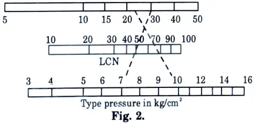
- g. Under normal circumstances, the LCN of the airfield and the ESWL and tyre pressure of the aircraft are known.
- h. The suitability of the airfield for receiving a particular aircraft is determined by comparing the LCN of the airfield with that of the aircraft.
Section 7 : Deposition of Sediments
a. Write a short note on littoral transport with erosion and deposition of sediments.
Ans. Littoral Transport with Erosion and Deposition :
- 1. Longshore drift is a geographical process that involves the movement of sediments (clay, silt, sand, and shingle) along a coast at an angle to the coastline, which is determined by the prevailing wind direction, swash, and backwash.
- 2. This process takes place in the littoral zone and in or near the surf zone. Littoral drift, longshore current, and longshore transport are all terms used to describe this process.
- 3. Longshore drift is controlled by many parts of the coastal system, with processes occurring within the surf zone having a substantial influence on sediment deposition and erosion.
- 4. Longshore currents can generate oblique breaking waves result in longshore transports.
- 5. Longshore drift can generally be defined in terms of the systems within the surf zone.
- 6. Longshore drift affects a wide range of sediment sizes since it works differently depending on the material (e.g. the difference in long shore drift of sediments from sandy beach to that of sediments from s shingle beach).
- 7. The oscillatory force of breaking waves, the migration of sediment due to the impact of breaking waves, and bed shear from long coast current all have a significant impact on sand.
- 8. Because shingle beaches are steeper than sandy beaches, plunging breaks are more likely to form, resulting in the majority of long shore transport occurring in the swash zone due to a lack of an extended surf Zone.
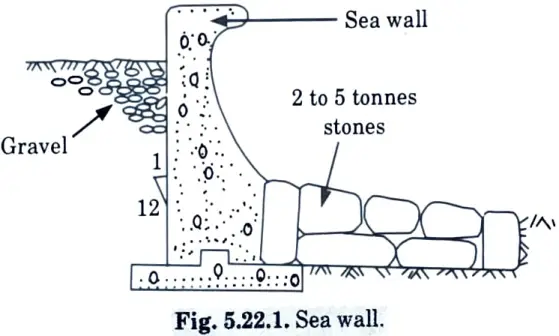
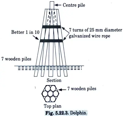
b. Explain following with neat sketch ;
i. Sea walls.
ii. Dolphins.
Ans. i. Sea walls :
- 1. They are the structures built along to the coast line to create a demarcation line between land and sea.
- 2. Sea walls are utilised where the land to be protected is developed and the effects of waves are severe.
- 3. These walls are very massive and expensive.
ii. Dolphins :
- 1. Dolphins are a type of structure that consists of a cluster of closely spaced piles. The heaps are connected together at the top with a cable.
- 2. These are marine structures used to dock ships.
- 3. Dolphins are used to tie up ships and move goods from one ship to another while they are moored on both sides.
- 4. Dolphins are primarily designed to withstand horizontal impact force, wind force, and water current forces from a docking vessel.
2 thoughts on “Railways, Waterway and Airport Engineering: Last year Question Paper Questions with Answer”