
Table Of Contents
B.Tech AKTU Quantum Book looks into the field of Optical Communication. Learn how to grasp this cutting-edge technology by accessing essential notes, repeated questions, and important insights. Unit-1 Introduction to Optical Communication
Dudes 🤔.. You want more useful details regarding this subject. Please keep in mind this as well.

Important Questions For Optical Communication:
*Quantum               *B.tech-Syllabus
*Circulars                *B.tech AKTU RESULT
* Btech 3rd Year     * Aktu Solved Question Paper
Q1. Draw a block diagram of fiber optic communication system and describe the function of each component.
Ans. 1. Fig. shows the block diagram of optical fiber communication.
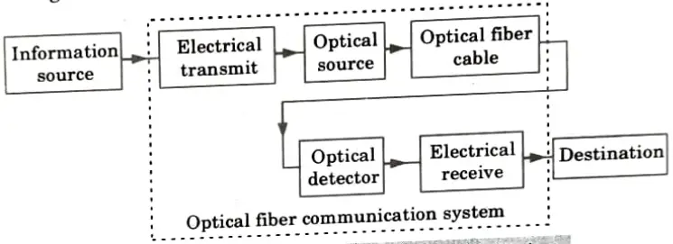
- 2. The information source transmits an electrical signal to the transmitter, which is made up of an electrical stage that powers an optical source and modulates the light wave carrier.
- 3. An electrical optical conversion is provided by the optical source. It might be an LED or a semiconductor laser.
- 4. The receiver is an optical detector that drives the next electrical stage, providing the demodulation of the optical carrier. The transmission channel is an optical fiber cable.
- 5. Photodiodes, photo transistors, and photo conductors may be used in some cases to detect optical signals and convert them into electrical signals.
- 6. As a result, the optical link requires electrical interfacing at both ends.
Q2. What are the various advantages of optical fiber communication system ?
Ans. Advantages of optical fiber communication system:
- 1. Enormous potential bandwidth: A far wider potential transmission bandwidth is produced by an optical carrier frequency in the 1013–1016 Hz range than by a metallic cable system. The ability of optical fiber systems to transmit information has thus far outperformed even the greatest copper cable systems.
- 2. Small size and weight: The diameter of an optical fiber is typically not much larger than that of a human hair. Such fibers are substantially smaller and lighter than equivalent copper wire, even when they are wrapped in protective coatings.
- 3. Electrical isolation: As glass and polymer are electrical insulators, earth loop and interface issues are not present in optical fibers made of these materials.
- 4. Signal security: Optical fibers offer a high level of signal security since their light does not radiate forth very much.
- 5. Low transmission loss: It has been possible to create optical fibers with losses as low as 0.2 dB km-1. Repeater links will be necessary after travelling hundreds of kilometers.
- 6. Ruggedness and flexibility: Despite the fact that optical fibers can be made with extremely high tensile strengths, protective coatings are still necessary.
- 7. System reliability and ease of maintenance: Reliability is good and maintenance is simple because fewer repeaters or line amplifiers are needed.
- 8. Potential low cost: The glass used as the primary optical fiber transmission medium is typically manufactured from sand, which is not a finite resource. Hence, optical fibers have the potential to provide low cost line connectivity when compared to copper connections.
Q3. What are skew rays ?
Ans.
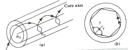
- 1. Skew rays are the more numerous rays that travel through the fiber in a helical pattern than meridional rays.
- 2. This kind of beam does not travel along the fiber axis while being transmitted.
- 3. The skew ray routes in two dimensions are quite challenging to visualize.
- 4. From Fig. it is observed that the helical path traced through the fiber gives a change in direction of 2𝛶 at each reflection where 𝛶 is the angle between the projection of the ray in two dimensions and radius of fiber core at the point of reflection.
- 5. Rather than the input condition to the fibre, the number of reflections skew rays experience will determine where they exit from the fibre in air.
- 6. Skew rays tend to have a smoothing impact on the distribution of the light as it is transmitted, creating a more uniform output when the light input to the fiber is not uniform.
- 7. The number of reflections the skew rays encounter determines how much smoothing is applied.
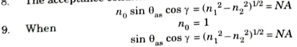
- 8. The acceptance conditions for skew rays are:
Q4. Explain modes in a planar guide. Also state the formation of modes in a planar dielectric guide.
Ans.
- 1. The simplest type of optical waveguide is the planar guide. We can assume that it is made up of a slab of n1-refractive-index dielectric positioned between two n2-refractive-index areas.
- 2. It is helpful to take into account the interference of plane wave components within this dielectric waveguide in order to obtain a better model for optical propagation.
- 3. A plane monochromatic wave propagating in the direction of the ray path within the guide as shown in Fig.(a).
- 4. As the refractive index within the guide is n1, the optical wavelength in this region is reduced to 𝜆/n1, while th¹ vacuum propagation constant is increased to n1k.
- 5. When 𝜃 is the angle between the wave propagation vector or the equivalent ray and the guide axis, the plane wave can be resolved into two component plane waves propagating in the z and x directions, as shown in Fig.
- 6. The component of the phase propagation constant in the z direction 𝛽z is given by:

- 7. The component of the phase propagation constant in the x direction 𝛽x is

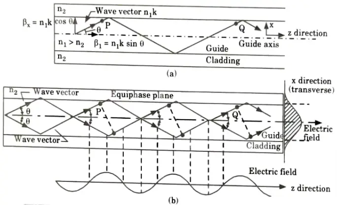
- 8. The component of the plane wave in the x-direction is reflected at the interface between the higher and lower refractive index media.
- 9. When the total phase change after two successive reflections at the upper and lower interfaces (between the points P and Q) is equal to 2 m𝜋 radians, where m is an integer, then constructive interference occurs and a standing wave is obtained in the x-direction.
- 10. This situation is illustrated in Fig.(b), the optical wave is effectively confined within the guide and the electric field distribution in the x-direction does not change as the wave propagates in the z-direction.
- 11. The sinusoidally varying electric field in the z-direction is also shown in Fig.(b).
- 12. The stable field distribution in the x-direction with only periodic z dependence is known as a mode.
- 13. A specific mode is obtained only when the angle between the propagation vectors or the rays and the interface have a particular value, as indicated in Fig.(b).
- 14. In effect, eq. (1.13.1) and eq. (1,13.2) define a group or congruence of ravs which in the case described represents the lowest order mode.
- 15. Hence the light propagating within the guide is modes, formed into discrete each specified by a distinct value of 𝜃. 16. These modes have a periodic z dependence of the form exp (- j𝛽z2) where 𝛽z, becomes the propagation constant for the mode as the modal field pattern is invariant except for a periodic z dependence.
Q5. Explain Goos-Hanchen shift.
Ans.
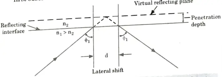
- 1. Through physical observation, it is possible to understand the phase change that results from the total internal reflection of a light beam on a planar dielectric contact.
- 2. Close inspection reveals that the reflected beam is laterally moved from the trajectory anticipated by straightforward ray theory analysis, as shown in Fig.
- 3. This lateral displacement is known as the Goos-Hanchen shift, after its first observer.
Q6. Define mode coupling in cylindrical fiber.
Ans.
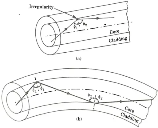
- 1. Waveguide disturbances, such as differences in the core diameter, abnormalities at the core cladding interface, and variations in refractive index, may alter the fiber’s ability to propagate light waves.
- 2. Depending on the particular perturbation, these will have the effect of linking energy moving in one mode to another.
- 3. The understanding of this event is aided by ray theory, as shown in Fig., which depicts two different types of disturbance. It is obvious that the beam no longer maintains the same angle with the axis in both scenarios.
- 4. This corresponds to a shift in the light’s propagation mode according to electromagnetic wave theory.
- 5. Hence, even when the fiber is of extraordinarily high quality and is not stretched or bent by its surroundings, individual modes typically do not propagate along the length of the fiber without significant energy transfers to adjacent modes. The term “mode coupling” or “mixing” refers to this mode conversion.
- 6. Mode coupling affects the transmission properties of fibers in several important ways, a major one being in relation to the dispersive properties of fibers over long distances.

Optical Communication Btech Quantum PDF, Syllabus, Important Questions
| Label | Link |
|---|---|
| Subject Syllabus | Syllabus |
| Short Questions | Short-question |
| Question paper – 2021-22 | 2021-22 |
Optical Communication Quantum PDF | AKTU Quantum PDF:
| Quantum Series | Links |
| Quantum -2022-23 | 2022-23 |
AKTU Important Links | Btech Syllabus
| Link Name | Links |
|---|---|
| Btech AKTU Circulars | Links |
| Btech AKTU Syllabus | Links |
| Btech AKTU Student Dashboard | Student Dashboard |
| AKTU RESULT (One VIew) | Student Result |