
Table Of Contents
Quantum Notes’ essential, commonly asked questions can help you prepare for the Aktu Btech Microprocessor and Microcontroller exam. Improve your comprehension to perform better on your examinations right away! Unit-3 16-bit Microprocessor
Dudes 🤔.. You want more useful details regarding this subject. Please keep in mind this as well.

Important Questions For Microprocessor and Microcontroller:
* Aktu Quantum          * B.tech-Syllabus
* Circulars                     * B.tech AKTU RESULT
* Btech 3rd Year          * Aktu Solved Question Paper
Q1. State the features of 8086. Also explain the difference between microprocessor 8085 and 8086.
Ans. A. Features of 8086:
- 1. A 16-bit microprocessor is the 8086. The internal registers, the arithmetic logic unit, and the majority of its instructions are made to function with 16-bit binary data.
- 2. The 8086 features a 16-bit data bus, allowing it to transfer either 16 or 8 bits at a time and read or write data to or from memory.
- 3. The 8086 has a 20-bit address bus, so it can directly access 220 memory locations.
- 4. The 8086 contains an address and data bus that is multiplexed, which decreases the number of pins required but slows down data transport.
- 5. For the 8086 to offer optimal internal timing, one phase clock with a 33% duty cycle is required.
- 6. The 8086 supports operations on bits, bytes, words, and blocks.
- 7. There are two operating modes for the 8086, called the minimum mode and the maximum mode.
- 8. 8086 supports multiprogramming and pipelining.
B. Differences between 8085 and 8086:
| S. No. | 8085 | 8086 |
| 1 | 8085 is a 8-bit microprocessor. | 8086 is a 16-bit microprocessor. |
| 2. | 8085 has 16 address lines. | 8086 has 20 address lines. |
| 3. | 8085 has only five flags. | 8086 has nine flags. |
| 4. | It does not support pipelining. | It supports pipelining. |
| 5. | 8085 operates on clock cycle with 50 % duty cycle. | 8086 operates on clock cycle with 33 % duty cycle. |
Q2. What is the memory segmentation in 8086 ? Explain the advantages of segmentation.
Ans. A. Memory segmentation:
- 1. In the segmented addressing, on the other hand, the available memory space is divided into “chunks” called segments. Sucha memory is known as segmented memory.
- 2. In 8086 system the available memory space is 1 Mbytes. This memory is divided into number of logical segments.
3. Each segment is 64 Kbytes in size and addressed by one of the segment registers. - 4. The 16-bit contents of the segment register gives the starting/base address of a particular segment, as shown in Fig.
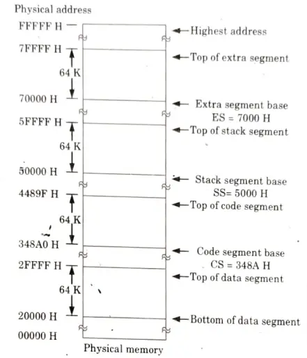
- 5. To address a specific memory location within a segment we need an offset address.
- 6. The offset address is also 16-bit wide and it is provided by one of the associated pointer or index register.
B. Rules for memory segmentation:
- 1. The four segments can overlap for small programs. In a minimum system all four segment can start at the address 00000 H.
- 2. The segment can begin/start at any memory address which is divisible by 16.
C. Advantages of memory segmentation :
- 1. It permits the memory addressing capacity to be 1 MB despite the fact that each instruction’s address is just 16 bits.
- 2. It enables the use of multiple code data, stack, and extra segments, allowing instruction code, data, and programme segments to be longer than 64 KB.
- 3. It makes it possible to use distinct memory spaces for programmes, data, and stacks.
- 4. It helps with multiple programming.
Q3. Write a short note on Direct Memory Access (DMA) controller.
Ans.
- 1. A common I/O approach for quick data transfer is Direct Memory Access.
- 2. Because each instruction needs to be fetched and processed, status check IO and interrupt I/O data transfer is rather slow.
- 3. In DMA, the MPU gives a device known as a DMA controller control over the buses.
- 4. Bypassing the MPU, the controller coordinates data flow between memory and a peripheral under its control.
- 5. The two important signals in DMA controller are:
- a. HOLD:
- i. The 8085 is being asked to use the address and data buses by this active high input signal from another master. The MPU releases the buses in the subsequent machine cycle after receiving the Hold request.
- ii. The Hold acknowledge (HLDA) signal is sent, and all buses are tri-stated. Upon the lowering of HOLD, the MPU takes over control of the buses.
- b. HLDA (Hold acknowledge): This signal, which is active and has a high output, signifies that the MPU is giving up control of the buses.
- a. HOLD:
- 6. These signals are used by a DMA controller to request the MPU to manage the buses as if it were a peripheral. Chip select line buses and control signals are used by the MPU to connect with the controller. The controller, however, assumes the function of a processor for data transport after it has taken control.
- 7. To perform this function the DMA controller should have:
- i. A data bus.
- ii. An address bus.
- iii. Read/Write control signals.
- iv. Control signals to disable its role as a peripheral and to enable its role as a processor.
- 8. This process is called switching from the slave mode to the master mode.
Q4. With the help of the block diagram, describe 8237 DMA controller in detail.
Ans.
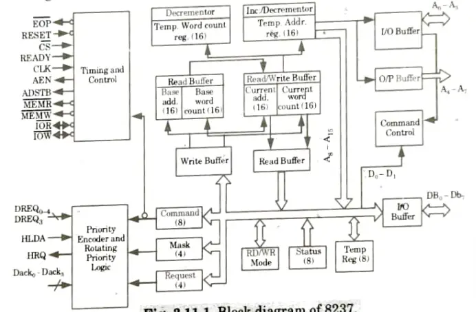
- 1. The internal block diagram is shown in Fig.
- 2. The 8237 contains three basic block of its operational logic.
- 3. Internal timings and external control signals are produced by the timing and control block.
- 4. Prior to handling a DMMA request, the programmed command control block decodes the different commands the CPU issues to the 8237. Additionally, it decodes the mode control word that is used during services to choose the DMA type.
- 5. The priority encoder block determines the order of priority between DMA channels that are concurrently requesting the service.
- 6. The timing and control block obtains the required timing from the input of the clock.
- 7. Internal registers: The 8237A contains 344 bits internal memory in the form of registers, such as basé address registers, current address registers, temporary address registers etc.
Q5. What is USART? What are its features ?
Ans. A. 8251 USART:
- 1. 8251A Universal Synchronous Asynchronous Receiver and Transmitter (USART) is compatible with Intel’s processors.
- 2. This may be programmed to operate in any of the serial communication modes built into it.
- 3. This chip converts the parallel data into a serial stream of bits suitable for serial transmission.
- 4. It is also able to receive a serial stream of bits and convert it into parallel data bytes to be read by a microprocessor.
B. Features of 8251 USART:
- 1. Single +5 V supply.
- 2. Compatible with 8085 and 8086/8088 CPU.
- 3. Supports both synchronous and asynchronous modes of operations.
- i. In synchronous mode it supports 5-8 bit characters, internal or external character synchronization at receiver, automatic sync insertion at transmitter.
- ii. In asynchronous mode it supports 5-8 bit characters, clock rate selectable 1, 16 or 64 times baud rate, break character generation, ‘1, 11/2 or 2 stop bits, false start bit detection, odd, even or no parity generation and detection, automatic breaks detect circuitry are also available.
- 4. Transmitter and receiver contain full duplex, double buffered system.
- 5. Error detection-Parity, overrun, framing.
- 6. Separate TXC and RXC clock inputs for transmitter and receiver. So transmitter and receiver can be operated in different baud rates.
Q6. Define the modes of 8254 PIT in detail with the help of diagrams.
Ans.
- 1. Mode 0 (interrupt on terminal count): The OUT is initially low in this mode. Once a count has been placed into the register, it is decremented every cycle until it hits zero, at which point the OUT signal is high. You can use this as an interruption. Unless a new count or a command word is loaded, the OUT stays high.
- 2. Mode 1 (Hardware-retriggerable one-shot): The OUT starts off high in this mode. The OUT goes low when the Gate is activated and goes high again at the conclusion of the count, producing a one-shot pulse.
- 3. Mode 2 (Rate generator): This mode is used to produce a pulse at a specific interval that is equal to the clock period. The OUT remains high when a count is loaded until the count reaches 1, at which point it drops to low for one clock cycle. The pulse is continuously generated, and the count is automatically reloaded.
- 4. Mode 3 (Square wave generator): When a count is loaded in this way, the OUT is high. Every clock cycle, the count is reduced by two, and when it hits zero, the OUT goes low, reloading the count. Continuous repetition of this results in the generation of a square wave with period equal to the count period.
- 5. Mode 4 (Software-triggered strobe): In this mode, the OUT is initially high; it goes low for one clock period at the end of the count. The count must be reloaded for subsequent outputs.
- 6. Mode 5 (Hardware-triggered strobe): This mode is similar to Mode 4, except that it is triggered by the rising pulse at the gate. Initially, the OUT is low, and when the Gate pulse is triggered from low to high the count begins. At the end of the OUT count, the goes low for the clock period.

Microprocessor and Microcontroller Btech Quantum PDF, Syllabus, Important Questions
| Label | Link |
|---|---|
| Subject Syllabus | Syllabus |
| Short Questions | Short-question |
| Question paper – 2021-22 | 2021-22 |
Microprocessor and Microcontroller Quantum PDF | AKTU Quantum PDF:
| Quantum Series | Links |
| Quantum -2022-23 | 2022-23 |
AKTU Important Links | Btech Syllabus
| Link Name | Links |
|---|---|
| Btech AKTU Circulars | Links |
| Btech AKTU Syllabus | Links |
| Btech AKTU Student Dashboard | Student Dashboard |
| AKTU RESULT (One VIew) | Student Result |