
With the B.Tech AKTU Quantum Book, you can explore the world of Electronic Instrumentation and Measurements. Access critical notes, frequently asked questions, and essential insights for success. Unit-5 Instrumentation
Dudes 🤔.. You want more useful details regarding this subject. Please keep in mind this as well.

Important Questions For Electronic Instrumentation and Measurements:
*Quantum               *B.tech-Syllabus
*Circulars                *B.tech AKTU RESULT
* Btech 3rd Year    * Aktu Solved Question Paper
Q1. For a transducer describe the following:
i. Input characteristics;
ii. Output characteristics.
Ans. Input characteristics :
- 1. Type of input and operating range: The type of input it will measure and its operational range choose the transducer to use. The transducer’s capabilities determine the top limit, whereas the error determines the lower limit. A good resolution must be present in the transducer.
- 2. Loading effects: The transducer must have no loading effect on the input.
Output characteristics:
- 1. Type of electrical output: The transducer can produce voltage, current, impedance, or a time function of these amplitudes as its output. which need to be adjusted so they may be utilized by instrumentation systems in later phases.
- 2. Output impedance:
- i. In order to reduce the effect of loading, the output impedance must be as low as possible. The quantity of power that will be delivered to the instrumentation system’s next stage is determined by the output impedance.
- ii. When the forward impedance is low compared to the output impedance and the output impedance is low, the transducer exhibits the properties of a constant voltage source and a constant current source.
- 3. Useful output range: The lower output range of the transducer is limited by the noise signals and upper limit is set by maximum useful input level.
Q2. Enlist the factors affecting the choice of transducers.
Ans.
- 1. Operating principle: The transducers are selected on the basis of operating principle i.e., whether resistive, inductive, capacitive, piezoelectric, optoelectronic etc.
- 2. Sensitivity: The transducers must be sensitive enough to produce detectable output.
- 3. Operating range: It should maintain the range as per the requirement and should have good resolution.
- 4. Accuracy: High degree of accuracy is acquired and gives small values of repeatability.
- 5. Cross sensitivity: While measuring the mechanical quantities, this factor is taken into account. There are instances where the transducer is subjected to changes in one plane while the real quantity is being measured in another.
- 6. Static characteristics : Low non-linearity, low hysteresis, good resolution, and high repeatability are requirements for transducers. Transducers must be immune to the effects of temperature changes and load alignment.
- 7. Stability and reliability: Transducer performance should be extremely stable. They must be dependable, meaning that even if a transducer malfunctions, the instrumentation system should still function well.
- 8. Errors: The transducers should maintain the expected input-output relationship.
- 9. Transient and frequency response: The transducers should have a flat frequency response curve and the desired time domain requirements, such as peak overshoot, rise time, and settling time.
- 10. Loading effects: The transducers must have high input impedance and low output impedance to avoid loading effects.
Q3. Explain with diagram of Hall effect transducer.
Ans. Hall Effect transducer:
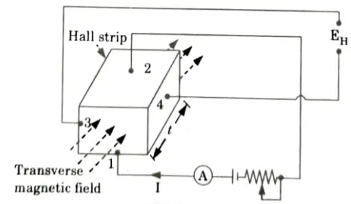
- 1. According to the Hall Effect transducer’s basic operating principle, a potential difference is created between the conductor’s opposing edges when a strip of conducting material conducts a current in the presence of a transverse magnetic field.
- 2. The Hall Effect, current, magnetic field intensity, and conductor property all affect how much voltage there is.
- 3. Depending on the densities and mobilities of the carriers, the Hall Effect can be found in metals and semiconductors in variable degrees.
- 4. Let’s think about the locations where leads 1 and 2 of the strip get current.
- 5. When there is no transverse magnetic field revolving around the strip, the output leads attached to edges 3 and 4 are at the same potential.
- 6. An output voltage is visible across the output leads when a transverse magnetic field traverses the strip.
- 7. This voltage is proportional to the current and the field strength. The output voltage is
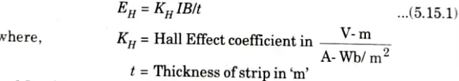
and I and B are respectively the current in ampere and flux density in Wb/m2.
Thus, the voltage produced may be used for measurement of either the current I or the magnetic field strength B.
Q4. Describe with diagram the moving magnet type transducer used for measuring linear velocity. Also enlist its merits and demerits.
Ans. Moving magnet type velocity transducer:
- 1. This utilizes the output voltage (e0) produced in coil on account of change in flux linkage, resulting from changes in reluctance.
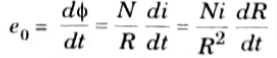
- 2. If average value of reluctance R is greater than the variations in R, the Ni/R2 is approximately constant. Thus, rate change of flux is proportional to rate change of reluctance directly.
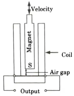
- 3. As R varies directly with the size of the air gap, the output voltage is exactly proportional to the rate of air gap change and, consequently, to the velocity.
- 4. The solenoid with N turns, as indicated, provides the constant mmf (Ni).
- 5. An instrument whose speed needs to be monitored is tightly linked with a permanent magnet that produces a constant polarising field in the shape of a rod.
- 6. The polarity of output determines the direction of motion.
Merits:
- i. Maintenance is negligible.
- ii. Output voltage is linearly proportional to motion.
- iii. These are robust and inexpensive to manufacture.
Demerits:
- i. Performance is adversely affected by stray magnetic fields.
- ii. Frequency response is limited.
Q5. Describe various electrical methods used for measurement of liquid level. Also enlist their merits and limitations.
Ans. The various methods of liquid level measurements are:
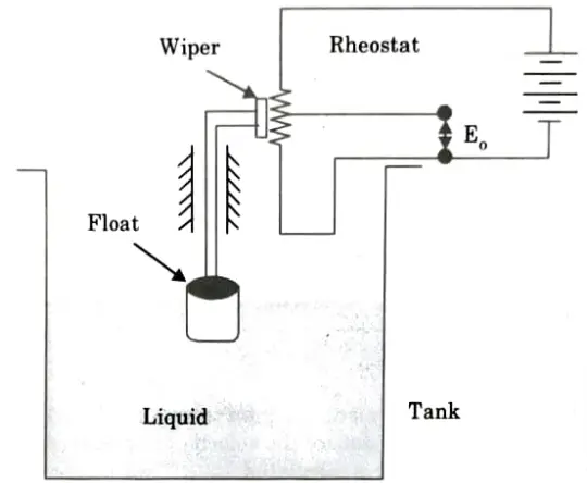
1. Float-operated Rheostatic liquid level gauge:
- i. The schematic diagram of the float-actuated resistive rheostat is shown in Fig.
- ii. The arm of a rheostat is moved by the slider passing over its resistive component when the float displacement activates it.
- iii. As a result of a circuit resistance change, the liquid level in the tank is directly proportional to this change in resistance.
2. Float Ultrasonic level gauge:
- i. In this, a transmitter incidentally sends out sound waves, and a receiver picks up the reflected waves.
- ii. The amount of time it takes for the wave to travel from the liquid’s surface to the receiver depends, in inverse proportion to the liquid level.
- iii. Determining the total duration allows for a fairly precise determination of liquid level fluctuations.
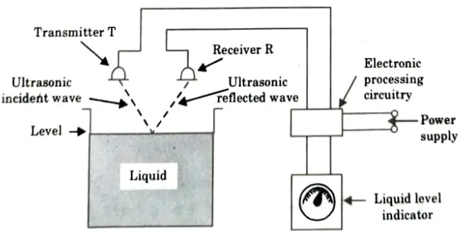
- iv. The instrument is pricey and requires a high level of knowledge and skill to use, despite the fact that its working concept is very straightforward.
- v. Yet, its broad range of applications in level measuring of various liquid and solid substances is its fundamental advantage.
Q6. Explain working principle of piezo-electrie transducer with diagram.
Ans.
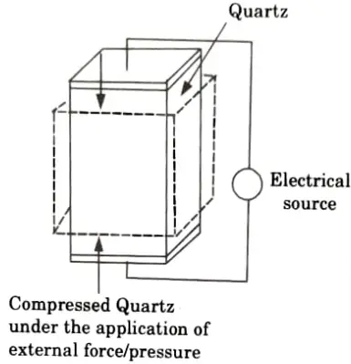
- 1. A device that uses the piezoelectric effect to measure changes in acceleration, pressure, strain, temperature, or force by turning this energy into an electrical charge is known as a piezoelectric transducer (also known as a piezoelectric sensor).
- 2. A crystal is elastically bent when pressure is applied. This deformation causes an electric charge to flow (which lasts for a period of a few seconds).
- 3. The electric signal that is produced can be measured to determine the pressure that was applied to the crystal.
- 4. These sensors are employed to measure quickly changing pressures brought on by blasts, explosions, pressure pulsations (from rocket motors, engines, compressors), or other causes of shock or vibration. They are unable to detect static pressures.
- 5. Piezoelectric sensors are used to measure dynamic forces such oscillation, impact, and high-speed compression or tension as well as pressure, acceleration, and these forces.
- 6. It includes piezoelectric ionic crystal components like Quartz, as depicted in Fig. These materials stretch or contract when pressure or force is applied.
- 7. The charge over the substance shifts and redistributes during this operation. The material’s faces become positively and negatively charged, respectively.
- 8. The net charge g on the surface is proportional to the amount x by which the charges have been displaced. The displacement is proportional to force. Therefore we can write,
q = kx = SF
where k = Constant
S = Constant termed the charge sensitivity

Electronic Instrumentation and Measurements Btech Quantum PDF, Syllabus, Important Questions
| Label | Link |
|---|---|
| Subject Syllabus | Syllabus |
| Short Questions | Short-question |
| Question paper – 2021-22 | 2021-22 |
Electronic Instrumentation and Measurements Quantum PDF | AKTU Quantum PDF:
| Quantum Series | Links |
| Quantum -2022-23 | 2022-23 |
AKTU Important Links | Btech Syllabus
| Link Name | Links |
|---|---|
| Btech AKTU Circulars | Links |
| Btech AKTU Syllabus | Links |
| Btech AKTU Student Dashboard | Student Dashboard |
| AKTU RESULT (One VIew) | Student Result |