Table Of Contents
With the B.Tech AKTU Quantum Book, you may explore the world of Electronic Instrumentation and Measurement. Access critical notes, repeated questions, and vital ideas for excellence. Unit-4 Electronic Measurements
Dudes 🤔.. You want more useful details regarding this subject. Please keep in mind this as well.

Important Questions For Electronic Instrumentation and Measurements:
*Quantum               *B.tech-Syllabus
*Circulars                *B.tech AKTU RESULT
* Btech 3rd Year    * Aktu Solved Question Paper
Q1. Explain the working of electronic wattmeter.
Ans.
- 1. For direct, tiny power measurements or for power measurements at frequencies outside the capabilities of electrodynamometer-type equipment, electronic wattmeters are utilised.
- 2. A simplified electronic wattmeter circuit is shown in Fig.
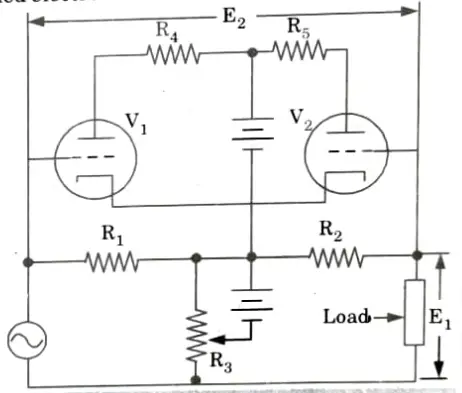
- 3. The matched triodes are operated in the non-linear portion of their characteristic grid-voltage, plate-current curves.
- 4. The symmetrical resistive T network between the generator and load will provide V1 and V2 voltages proportional to, and in phase with, the load current and voltage, respectively.
- 5. A source of AC power is connected to the load through the series resistors R1 and R2.
- 6. These two resistors are of equal value and are made small to prevent the voltage drop across them from reducing the load voltage appreciably.
- 7. R3 is made large enough to have negligible power consumption.
- 8. Therefore, the R3 voltage is equal to the load voltage, and the voltage across either series resistor is proportional to the difference in the output currents of the tubes.
- 9. The average value of the difference could be measured by a DC meter connected to read the voltage potential between the grids of V1 and V2.
- 10. This method is adequate only at low frequencies.
- 11. As the frequency increases, the stray capacitances and inductances also increase.
- 12. By utilizing pentodes in place of triode tubes, the frequency range of the electronic wattmeter can be increased up to 20 megahertz. An adjustment is made to the pentode’s operating parameters to make the plate current proportional to the sum of an exponential function of grid voltage and a linear function of plate voltage.
Q2. Explain storage oscilloscope.
Ans. Storage oscilloscope: Two storage techniques are used in oscilloscope CRTs: mesh storage and phosphor storage.
- 1. A dielectric material that has been deposited on a storage mesh serves as the storage target in a mesh-storage CRT. This mesh is positioned in the CRT between the standard phosphor target and the deflection plates.
- 2. When it strikes the dielectric substance, the writing beam the focussed electron beam of a typical CRT charges it positively.
- 3. The stored image is then reproduced on the screen by bombarding the storage target with low-velocity electrons from a flood gun, which are able to pass through the positively charged portions of the storage target and hit the standard phosphor target.
- 4. As a result, the mesh storage has a target for both storage and phosphor display. A small layer of phosphor is used in the phosphor storage CRT to act as both the store and the display element.
Mesh storage:
- 1. It is used to display Very Low Frequencies (VLF) signals and finds many applications in mechanical and biomedical fields.
- 2. A mesh storage CRT is shown in Fig.
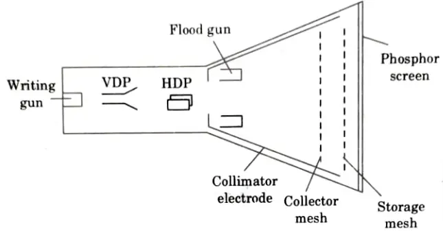
- 3. In addition to all the components of a typical CRT, it also has a dielectric substance put on a storage mesh, a collector mesh, flood guns, and a collimator.
- 4. By removing secondary emission electrons, the writing gun creates a positively charged pattern on the storage mesh or target.
- 5. A special electron gun called the flood gun is turned on to make a pattern apparent (even after many hours).
- 6. The electron paths are adjusted by the collimator electrode which continues a low voltage electrostatic lens system as shown in Fig.
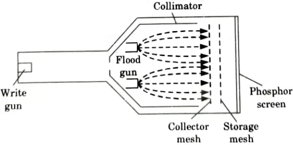
- 7. The collector mesh stops and collects the majority of the electrons. Only electrons close to the positive charge being stored are drawn to the storage target strongly enough to strike the phosphor screen.
- 8. The signal will now appear on the CRT and will continue to do so as long as the flood guns are operational.
- 9. A negative voltage is used to offset the positive charge that was stored, erasing the pattern from the storage mesh.
Q3. Explain dual trace oscilloscope and its application.
Ans. Dual trace oscilloscope:
- 1. It has a single electron gun, but before it reaches the deflection plates, the beam is divided into two distinct beams.
- 2. There are two different vertical input channels, A and B, and they each have their own preamplifier and attenuation stages.
- 3. As a result, each input’s amplitude as seen on the oscilloscope can be separately adjusted.
- 4. Using the delay line, two channels are combined into one vertical amplifier after preamplification.
- 5. The electronic switch has two standard operating modes, alternate and chop, which are chosen from the instrument’s front panel.
- 6. The alternate mode is shown in Fig.
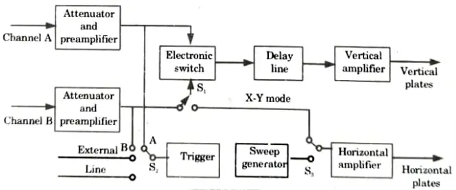
- 7. In this case, the electronic switch allows each channel to pass for one cycle of the horizontal sweep while switching back and forth between channels A and B.
- 8. Similar to a traditional oscilloscope, the display is blanked during the flyback and hold-off phases.
- 9. The screen will display a stable representation of both the waveform at channels A and B if the sweep speed is substantially faster than the CRT phosphor’s delay time.
- 10. Signals with very low frequency cannot be displayed in the alternate mode.
Applications:
- 1. Analyze signals produced by function generators.
- 2. Check response of a silicon, InGaAS, or avalanche photodiode.
- 3. Use with analog light meter output to visualize intensity of a source.
- 4. Troubleshoot electro-optical and electrical systems.
- 5. Observe a triggered event separately or relative to the trigger itself.
Q4. Explain the operation of sampling oscilloscopes.
Ans. A. Sampling oscilloscope:
- 1. By sampling the input waveform and reconstructing its shape from the sample, it is specifically designed for monitoring very high frequency signals.
- 2. Because the frequency range of a conventional oscilloscope is constrained by the gain bandwidth product of its vertical amplifier, such high frequency oscillations cannot be observed with one.
- 3. The sampling gate receives the input. It momentarily biases the sampling gate’s diode in the forward direction. Hence, the gate input capacitance is connected to the test point.
- 4. In order to allow the input signal to start the horizontal sweep, the signal frequency and sampled waveform are synchronized. This produces a delay in the vertical amplifier.
- 5. At the beginning of each sampling cycle, the trigger pulse activates the oscilloscope and a linear ramp voltage is generated.
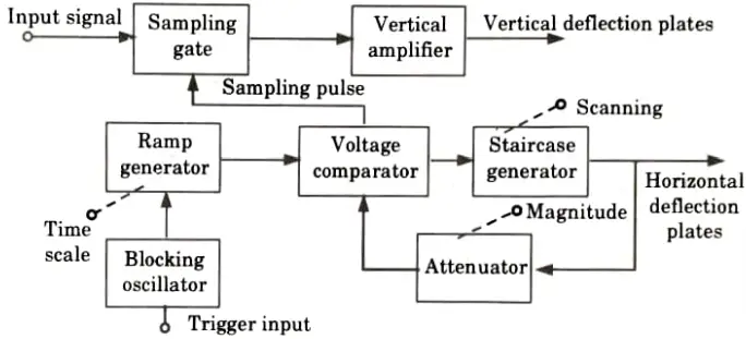
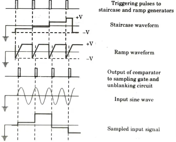
- 6. A voltage comparator receives this ramp voltage and compares it to a staircase generator that is allowed to advance one step while also applying a sample pulse to the sampling gate.
- 7. The input voltage sample is now applied to the vertical deflection plates after being amplified. After 50 MHz, between 500 MHz and 10 GHz, it can be used.
Q5. Discuss the spectrum analyzer with the help of block diagram.
Ans.
- 1. The analysis of the energy distribution over the frequency spectrum of an electrical signal is known as spectrum analysis.
- 2. The study offers insightful data on bandwidth, the consequences of various modulation types, and the creation of spurious signals.
- 3. Due to the capabilities and constraints of the apparatus, the spectrum analysis is divided into two main areas. They are:
- a. Audio frequency (AF) analysis.
- b. Radio frequency (RF) spectrum analysis.
- 4. Spectrum analyzers are complex devices that can graphically depict the amplitude as a function of frequency in a specific region of the RF spectrum.
- 5. These tools have numerous uses in pulse studies for measuring attenuation, FM deviation, and frequency.
- 6. A narrow band superheterodyne receiver and a CRO are the fundamental components of a modern spectrum analyzer.
- 7. The local oscillator’s frequency is changed to electronically tune the receiver.
- 8. The circuit includes a sawtooth generator that provides a ramp voltage to the voltage-tuned local oscillator’s frequency control element.
- 9. The local oscillator then repeatedly sweeps through its frequency band.
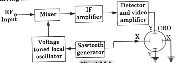
- 10. The CRO’s horizontal plates are concurrently subjected to the same sawtooth voltage.
- 11. The mixing stage’s input is applied with the RF signal that will be examined.
- 12. In order to achieve the desired intermediate frequency, the sawtooth generator causes the local oscillator to sweep through its frequency band (IF).
- 13. Only when the matching component is present in the RF input signal can an IF component be formed.
- 14. After being amplified and detected, the ensuing IF signals.
- 15. Then, they are applied to the CRO’s vertical deflection plates, resulting in a screen display of amplitude vs frequency.
Q6. Explain the working procedure of Q-meter.
Ans. A. Construction:
- 1. The fundamental components of a Q metre are the coil under investigation, a variable calibrated capacitor, and a variable-frequency AC voltage source. They are all linked in succession.
- 2. Voltmeters are used to measure the source voltage (E) and the capacitor voltage (VC).
- 3. The source’s voltage is adjusted to a useful level, and the desired measuring frequency is established.
B. Working procedure:
- 1. Q times the applied voltage equals the voltage across the coil or capacitor.
- 2. A voltmeter across the capacitor can be calibrated to read Q directly if a constant voltage is given to the circuit.
- 3. The circuit is powered by a broad range oscillator with a frequency range of 50 kHz to 50 MHz.
- 4. Capacitor C is adjusted to achieve resonance, which is seen when the voltage across C is at its highest level. When resonance is attained, the source is readjusted if necessary to the appropriate output level.
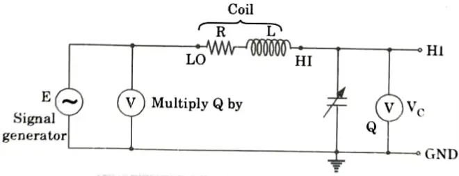
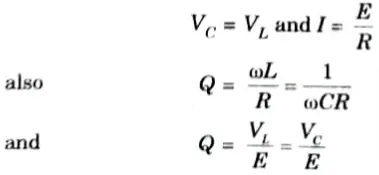
- 5. At resonance,

Electronic Instrumentation and Measurements Btech Quantum PDF, Syllabus, Important Questions
| Label | Link |
|---|---|
| Subject Syllabus | Syllabus |
| Short Questions | Short-question |
| Question paper – 2021-22 | 2021-22 |
Electronic Instrumentation and Measurements Quantum PDF | AKTU Quantum PDF:
| Quantum Series | Links |
| Quantum -2022-23 | 2022-23 |
AKTU Important Links | Btech Syllabus
| Link Name | Links |
|---|---|
| Btech AKTU Circulars | Links |
| Btech AKTU Syllabus | Links |
| Btech AKTU Student Dashboard | Student Dashboard |
| AKTU RESULT (One VIew) | Student Result |