With the B.Tech AKTU Quantum Book, you can enter the world of Electronic Instrumentation and Measurements. Access important notes, frequently asked questions, and helpful ideas for success. Unit-3 Measuring Methods and AC Bridges
Dudes 🤔.. You want more useful details regarding this subject. Please keep in mind this as well.

Important Questions For Electronic Instrumentation and Measurements:
*Quantum               *B.tech-Syllabus
*Circulars                *B.tech AKTU RESULT
* Btech 3rd Year    * Aktu Solved Question Paper
Q1. Classify the methods used for the measurement of resistance.
Ans. 1. Methods for measurement of resistance are classified as :
- i. Low resistance: All the resistance of the order of 1𝛺 and under may be classified as low resistance.
- ii. Medium resistance: This class includes resistance from 1𝛺 upwards to about 0.1 M𝛺.
- iii. High resistance: Resistance of the order of 0.1 M𝛺 and upwards are classified as high resistance.
2. Following are different methods which are used in measurement of resistance:
- i. For low resistance:
- 1. Ammeter-voltmeter method
- 2. Kelvin’s double bridge method
- 3. Potentiometer method.
- ii. For medium resistance:
- 1. Ammeter-voltmeter method
- 2. Substitution method
- 3. Wheatstone bridge method
- 4. Carey-Foster slide wire bridge method
- 5. Ohmmeter method.
- iii. For high resistance:
- 1. Direct deflection method
- 2. Loss of charge method
- 3. Meg-ohm bridge
- 4. Megger.
Q2. Draw the circuit of a Kelvin bridge, explain its operation, and derive the equation for the unknown resistance.
Ans.
- 1. Kelvin’s double bridge is used for measuring low resistances (micro ohms to 1𝛺).
- 2. It improves accuracy and is a variation of Wheatstone’s bridge.
- 3. It uses four terminal resistances for the low resistance arms and adds the concept of a second set of ratio arms, hence the name double bridge.
- 4. The circuit diagram is shown in Fig.
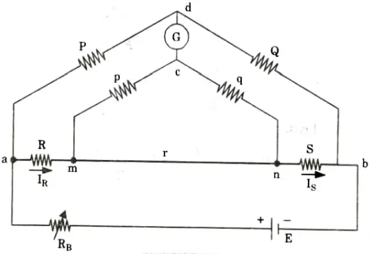
R = Unknown resistance
S = Standard resistance of the order of magnitude as R
r = Connecting link of low resistance
- 5. P,Q and p, q are two pairs of known non-inductive resistances and one pair P, p or Q,q is variable.
- 6. The ratio p/q is made equal to P/Q. Under balanced conditions there is no current through galvanometer
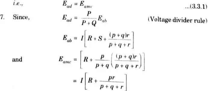
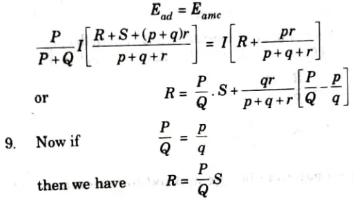
- 8. For balanced condition
Q3. Explain Wheatstone bridge method for calculation of medium resistances.
Ans. Wheatstone bridge method:
The bridge consists of four resistive arms P, Q, R and S together with a source of emf and a null detector (galvanometer).
Balance condition:
1. The galvanometer carries no current and displays no deflection when the bridge is balanced.
2. As a result, the bridge operates on the null deflection theory. The potential of Points B and D must be equal.
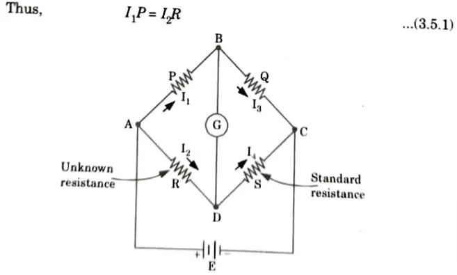
3. For zero current in galvanometer
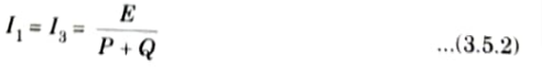

where, E = emf of battery
6. Combining eq. (3.5.1), (3.5.2) and (3.5.3), we obtain:
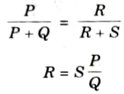
where, R = Unknown resistance.
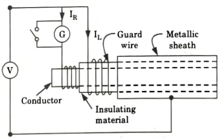
Q4. Explain direct deflection method of measurement of high resistance.
Ans.
- 1. In this method, a high resistance (1000 𝛺) and very sensitive moving coil galvanometer is connected in series with the resistances to be measured along with supply voltage.
- 2. By this method, insulation resistance can be obtained with respect to the deflection of galvanometer.
- 3. The galvanometer measures current IR between the conductor and metal sheath.
- 4. The leakage current, IL over the surface of insulating material are carried by guard wire.
- 5. The ratio of the voltage applied between conductor and metal sheath to the current flowing between them gives the insulation resistance of the cable.
Q5. Discuss the method of measurement of high resistance by Megger method.
Ans.
- 1. Insulation resistance is often measured in mega ohms. Megger is the name of the device used to measure insulating resistance.
- 2. It is made up of a direct reading ohmmeter and a hand-operated DC generator.
- 3. Fields for both are provided by permanent magnets.
- 4. There are three coils in the moving element: a current coil, a potential or pressure coil, and a compensating coil.
- 5. The coils are suspended over a fixed iron core in the shape of a C and are free to rotate.
- 6. Flexible leads or ligaments are used to join the coils to the circuit.
- 7. E and L are the test terminals. The current coil is connected in series with the terminal L.
- 8. The series resistance R limits the instrument’s operating range and safeguards the current coil in the event that the test terminals are short-circuited.
- 9. The pressure coil is connected across the generator terminals in series with a compensating coil and a protection resistance R.
- 10. A compensating coil is available to improve scale proportions and calibrate the device.
- 11. The pressure coil tends to align itself at a right angle to the permanent magnet field when the generator’s current passes through it.
- 12. The point at which this state occurs is designated as infinite resistance because no current flows through the current coil and the moving element moves to its most extreme anticlockwise position under the control of the pressure coil.
- 13. When the terminals L and E are short circuited, the current flowing through the current coil is sufficient to move the pointer to its extreme clockwise position, designated zero. This provides clockwise torque on the moving element.
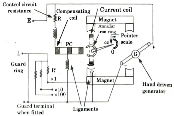
- 14. For any resistance connected between L and E, the opposing torque of the coils balances each other so that pointer comes to rest at some intermediate point on the scale.
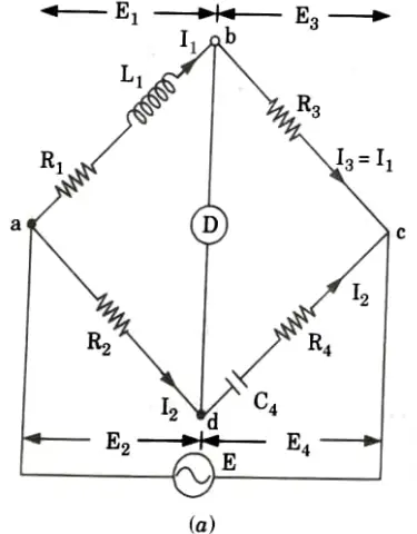
Q6. Draw the bridge arrangement and describe the Hay’s bridge for inductance measurement. Draw the phasor diagram.
Ans. 1. The Hay’s bridge is a modification of Maxwell’s bridge.
2. This bridge uses a resistance in series with the standard capacitor (unlike the Max well’s bridge which uses a resistance in parallel with the capacitor).
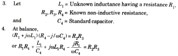
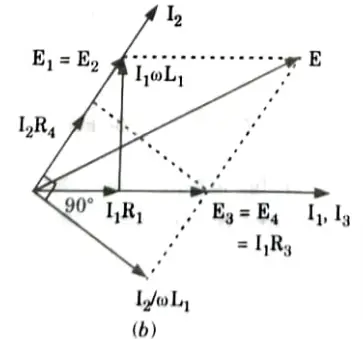
5. Separating the real and imaginary terms, we obtain
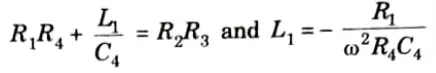
6. Solving the two equations, we have
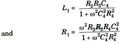
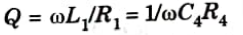
7. The Q factor of the coil is,
8. The frequency term appears in the formulas for the unknown inductance and resistance.
9. It so seems necessary to precisely determine the frequency of the supply source for the bridge.

Electronic Instrumentation and Measurements Btech Quantum PDF, Syllabus, Important Questions
| Label | Link |
|---|---|
| Subject Syllabus | Syllabus |
| Short Questions | Short-question |
| Question paper – 2021-22 | 2021-22 |
Electronic Instrumentation and Measurements Quantum PDF | AKTU Quantum PDF:
| Quantum Series | Links |
| Quantum -2022-23 | 2022-23 |
AKTU Important Links | Btech Syllabus
| Link Name | Links |
|---|---|
| Btech AKTU Circulars | Links |
| Btech AKTU Syllabus | Links |
| Btech AKTU Student Dashboard | Student Dashboard |
| AKTU RESULT (One VIew) | Student Result |