
Table Of Contents
With B.Tech AKTU Quantum Book, you can explore the world of Electronic Instrumentation and Measurements. Access critical notes, frequently asked questions, and useful ideas towards excellence. Unit-2 Electronic Instruments
Dudes 🤔.. You want more useful details regarding this subject. Please keep in mind this as well.

Important Questions For Electronic Instrumentation and Measurements:
*Quantum               *B.tech-Syllabus
*Circulars                *B.tech AKTU RESULT
* Btech 3rd Year    * Aktu Solved Question Paper
Q1. Write a short note on :
i. Op-amp voltage-follower voltmeter
ii. Op-amp amplifier voltmeter.
Ans. i. Op-amp voltage-follower voltmeter:
- 1. The circuit diagram of Op-Amp voltage-follower voltmeter is shown in Fig.

- 2. The input resistance of the voltage-follower is significantly larger than that of the emitter-follower. There is no base-emitter voltage drop from input to output, unlike the emitter follower.
- 3. The voltage-follower input (EB) is supplied to the Op-non-inverting Amp’s terminal in this circuit, and the feedback from the output is applied to the terminal on the inverting input.
- 4. The inverting terminal voltage tends to remain exactly identical to that at the non-inverting terminal thanks to the Op-extremely Amp’s high voltage gain and negative feedback. Hence, output voltage follows input voltage.
- 5. The attenuator is used for selecting the range of voltmeter.
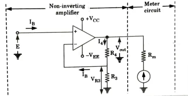
ii. Op-Amp amplifier voltmeter:
- 1. An IC Op-Amp can also be used to amplify low voltages to levels, measurable by a deflection meter. Op-Amp amplifier voltmeter circuit is Used for this purpose as shown in Fig.
- 2. The input voltage (E) is applied to the non-inverting terminal and voltage VR3 is feedback to the inverting terminal of the Op-Amp. The internal voltage gain of Op-Amp causes VR3 to be always equal to E. The output voltage is

Q2. Explain the working of precision rectifier based voltmeters.
Ans. A. Working principle of electronic voltmeter:
- 1. An Op-Amp voltage-follower AC voltmeter can be converted into an AC electronic voltmeter by connecting a rectifier in series with the meter circuit. Such a circuit is shown in Fig.
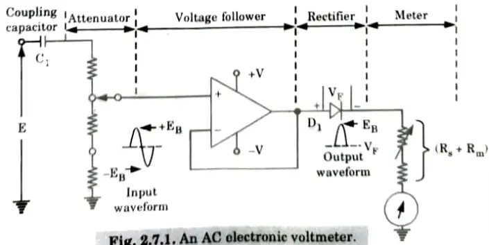
- 2. The Op-non-inverting Amp’s terminal input is applied with an AC input signal that will be monitored. Unwanted DC voltages are blocked in this circuit by coupling capacitor C1.
- 3. The voltage follower’s output is an exact replica of the AC input signal.
- 4. The rectifier receives this output voltage and produces a half-wave rectified version of the input signal. The metre circuit receives this rectified voltage.
- 5. The limitation of this circuit is that the voltage drop (VF) across the rectifier acts as an error which must be taken into account in design calculation when the instrument is indicating full scale.
- 6. This error can be avoided by using a precision rectifier.
B. AC electronic voltmeter using precision rectifier:
- 1. A precision rectifier is used to improve the accuracy of AC electronic voltmeter.

- 2. Fig. shows an AC electronic voltmeter using precision rectifier.
- 3. In this circuit, the cathode of rectifier D1 is used as the voltage-follower feedback connection to the inverting terminal rather than the amplifier output.
- 4. As a result, there is no rectifier voltage drop from input to output since the half-wave rectified output precisely matches the positive half-cycle of the input voltage.
Q3. What do you mean by loading effect ? How does electronic voltmeter help in minimizing the loading effect ?
Ans. A. Loading effect:
- 1. In order to measure the voltage in a circuit, a voltmeter is always connected across or in parallel with the measurement points.
- 2. If its resistance is too low, it may change the voltage in the circuit. The voltmeter loading effect is the term for this.
- 3. Where low levels are to be detected in electronic and communication circuits, loading effect arises.
B. Electronic voltmeter:
- 1. By supplying the necessary power for measurement by employing external circuits like amplifiers, electronic voltmeters avoid the loading effects.
- 2. The amplifiers enable low level signals in addition to providing power for operation.
- 3. As vacuum tubes and transistors are used as amplifiers in electronic voltmeters, an additional source of power can be used to operate the deflecting element of the PMMC instrument.
- 4. As a result, although the circuit whose voltage is being measured controls the voltmeter’s sensing element, the power required from the circuit is very little or even insignificant.
- 5. This indicates a very high input impedance in the voltmeter circuit.
- 6. Voltage measurements in many high impedance circuits, such as those found in communication equipment, depend on this property of electronic voltmeters.
Q4. Write a short note on multimeter probes.
Ans.
- 1. A connection is made between the test circuit and the measurement device using a probe.
- 2. Any conductor, such as a piece of bare wires, a multimeter lead, or an unterminated coaxial cable, may be used as a probe.
- 3. A probe simply transfers the least amount of energy possible from the circuit being tested to a measuring device with the highest degree of accuracy.
- 4. The ideal probe provides the following key attributes:
- i. Ease of connection.
- ii. Absolute signal fidelity.
- iii. Zero signal source loading.
- iv. Complete noise immunity.
- 5. There are many probes for use with multimeters that can extend the range of measurement. Some of these are given as:
i. High voltage probe:
- 1. In essence, a high voltage probe is a potential divider.
- 2. The voltage to be measured is often divided by a factor of 1000, essentially multiplying the instrument scales by 1000. A 10 V scale becomes a 10 kV scale as a result.

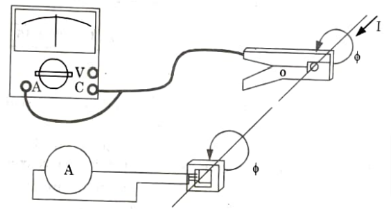
ii. High current probe:
- 1. By using a current transformer, the AC current probes lower the high levels of alternating current.
- 2. The conductor carrying the current to be measured is close to and open to the transformer’s core.
- 3. The transformer’s secondary windings control the amount of measured current. Hence, by using the current probe, a multimeter’s 1 mA AC scale is changed to a 1 A scale.
Q5. How are digital voltmeters classified ? What are the operating and performance characteristics of a digital voltmeter ?
Ans. A. Digital voltmeter:
- 1. Digital voltmeters basically function as analog-to-digital converters that display the measured voltage on a digital screen.
- 2. Unlike analogue instruments, which display pointer deflections on a continuous scale, digital voltmeters (DVMs) display measurements of DC or AC voltage as discrete digits.
- 3. It is a flexible and precise tool used in numerous laboratory measuring applications.
B. Classification of digital voltmeter:
- 1. Ramp-type DVM.
- 2. Dual-slope type DVM.
- 3. Integrating type DVM.
- 4. Successive approximation DVM.
C. Characteristics features of DVM:
- 1. Input range: From ± 1.000 V to ± 1000 V with automatic selection and overload indication.
- 2. Absolute accuracy: As high as ± 0.005 % of the reading.
- 3. Resolution: 1 part per million.
- 4. Stability: Short term, 0.002 % of the reading (for a 24 hour period), long term, 0.008 % of the reading (for a 6-month period).
- 5. Input resistance: Typically 10 M𝛺.
- Input capacitance: 40 pF.
- 6. Calibration: Internally from stabilized reference sources, independent of measuring circuit.
- 7. Output signals: In BCD form, for print output and further digital processing.
Q6. What is the importance of calibration in instrumentation ? Sketch the circuit for calibrating a wattmeter and explain the calibration procedure.
Ans. Importance of calibration:
- 1. Assurance of accurate measurements.
- 2. Ability to trace measurements to international standards.
- 3. Correct diagnosis of illness (medical reports).
- 4. Consumer protection (legal metrology).
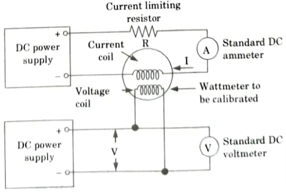
B. Circuit of calibration a wattmeter:
- 1. The calibration of a wattmeter combines the calibration of an ammeter and a voltmeter.
- 2. In Fig., a wattmeter is depicted with its voltage coil linked to one DC power source and its current coil attached to another.
- 3. The device as a whole calculates the power utilized by the load by using the ammeter and voltmeter to measure current and voltage, respectively.
- 4. The wattmeter’s two coils are the stationary coil and the moving coil. These two coils are connected in various circuits to measure power.
- 5. To measure the current in the circuit, the fixed coil is linked in series with the conventional ammeter. As a result, the current coil refers to the fixed coil.
- 6. When the moving coil is wired across the normal voltmeter, it measures a current inversely proportional to the voltage.
- 7. To reduce the current to a tiny amount, a large non-inductive resistance is connected in series with the moving coil.
- 8. The moving coil is also known as the pressure coil or voltage coil since it transmits current that is proportional to voltage.
- 9. P = VI is used to compute power. After the correct voltage and current for a particular wattmeter reading have been established, P = VI can be used to calculate the precise power.
- 10. The maximum voltage and maximum current must be avoided in order to protect the instrument. ‘

Electronic Instrumentation and Measurements Btech Quantum PDF, Syllabus, Important Questions
| Label | Link |
|---|---|
| Subject Syllabus | Syllabus |
| Short Questions | Short-question |
| Question paper – 2021-22 | 2021-22 |
Electronic Instrumentation and Measurements Quantum PDF | AKTU Quantum PDF:
| Quantum Series | Links |
| Quantum -2022-23 | 2022-23 |
AKTU Important Links | Btech Syllabus
| Link Name | Links |
|---|---|
| Btech AKTU Circulars | Links |
| Btech AKTU Syllabus | Links |
| Btech AKTU Student Dashboard | Student Dashboard |
| AKTU RESULT (One VIew) | Student Result |