With AKTU’s Question Paper, you may embark on an Exciting Power Quality and FACTS Journey. Improve your understanding, test your knowledge, and fly to exam achievement.
Dudes 🤔.. You want more useful details regarding this subject. Please keep in mind this as well.

Important Questions For Power Quality and FACTS:
*Quantum          *B.tech-Syllabus
*Circulars           *B.tech AKTU RESULT
* Btech 4th Year
Section A: Short Question In Power Quality and FACTS
a. Define transients and surges ?
Ans. The term transient is commonly used in electric circuit theory to describe voltage and current variations from one steady state to the next.
b. Define impulsive transients.
Ans. An impulsive transient is a unidirectional (either +ve or -ve) non-power frequency change in the steady-state condition of voltage, current, or both.
c. List two reasons for voltage sags.
Ans. Voltage sag (Voltage drops) or Dips:
- 1. A sag is a reduction in rms voltage or current of between 0.1 and 0.9 per unit at the power frequency for durations ranging from 0.5 cycle to 1 minute.
- 2. A short-duration voltage fall is referred to as sag in the power quality community.
d. Distinguish between static UPS and rotary UPS.
Ans.
| S. No. | Static UPS | Rotary UPS |
| 1. | There are no revolving parts in static uninterruptible power sources, such as motors or generators. | Rotary UPS systems use rotating parts to deliver continuous power to loads. |
| 2. | Static UPS systems are less reliable. | Rotary UPS systems are more reliable. |
e. Discuss the neutral voltage swing condition.
Ans.
- 1. Normally, neutral voltage should be within 0.5 V with respect to the ground.
- 2. But the voltage variation at neutral more than specified value is known as neutral voltage swing.
f. Electrical transients are created due to switching of UPS. Elaborate.
Ans. 1. Typically, we associate voltage notches with adjustable speed drives.
- 2. Voltage notches are also prevalent on the outputs of Uninterruptible Power Supply (UPS) units due to the power electronic switching circuitry connected with the UPS devices.
- 3. Without equipped with wave shaping and filtering electronics, the UPS output can contain significant notches.
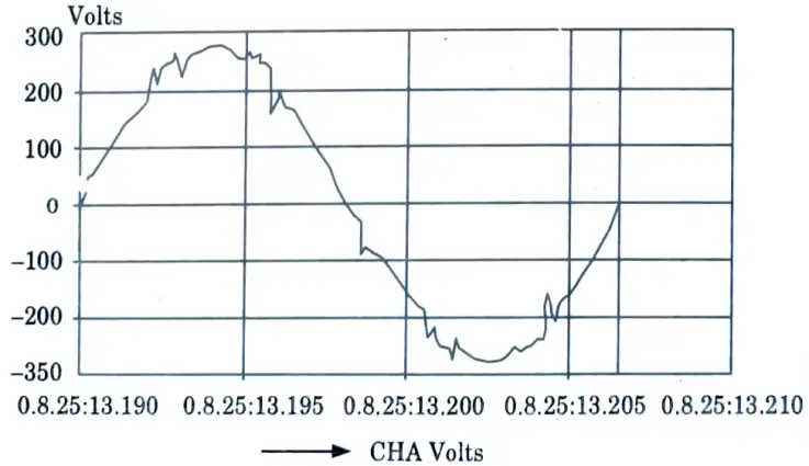
- 4. Fig. depicts the output waveform of a UPS unit producing 250 V output.
- 5. If the notch level goes too high, sensitive communication or data-processing loads may experience problems.
- 6. The voltage notch phenomenon is a recurring event, despite the fact that we characterize transients as subcycle events.
g. Explain any two FACT controller devices.
Ans. A. SVC :
- 1. SVC stands for Static VAr compensator.
- 2. “A shunt linked static VAr generator or absorber whose output is regulated to interchange capacitive or inductive current in order to maintain or manage particular parameters of the electric power system,” according to the IEEE.
B. STATCOM :
1. STATCOM stands for Static Synchronous Compensator.
- 2. STATCOM is defined as a “static synchronous generator operated as a shunt connected static VAr compensator whose capacitive or inductive output current can be regulated independently of the AC system voltage” by the IEEE.
h. Discuss the working of SSC.
Ans. A STATCOM is a reactive-power source that can be regulated. It generates and absorbs reactive power solely through electronic processing of voltage and current waveforms in a voltage-source converter (VSC).
i. List two devices used for measuring power quality and harmonics.
Ans. 1. Harmonic analyzers.
2. Transient disturbance analyzers.
j. Analyze the role of harmonics on the communication lines.
Ans.
- 1. Harmonic currents flowing through a utility distribution system or an end-user facility might cause interference in communication circuits sharing a common channel.
- 2. Common harmonic currents induce voltages in parallel conductors that frequently fall inside the bandwidth of regular voice transmissions.
- 3. Harmonics between 540 (ninth harmonic) and 1200 Hz are very bothersome. The induced voltage per ampere of current rises as frequency rises.
- 4. Triplen harmonics (3rd, 9th, and 15th) are particularly bothersome in four-wire systems because they are in phase in all conductors of a three-phase circuit and thus add directly in the neutral circuit, which has the most exposure to the communications circuit.
- 5. Power system harmonic currents are connected into communication circuits via induction or direct conduction.
Section B : Long Questions Power Quality and FACTS
a. Differentiate between harmonics and inter-harmonics.
Ans.
| S. No. | Harmonics | Inter-harmonics |
| 1. | A harmonic in an electric power system is a voltage or current that is a multiple of the system’s fundamental frequency. | Inter-harmonics are voltages or currents with frequency components that are not integer multiples of the frequency at which the supply system is meant to operate (e.g., 50 or 60 Hz). |
| 2. | Harmonics are periodic at the fundamental frequency. | Inter- harmonics are not periodic at the fundamental frequency. |
| 3. | Harmonic distortion is caused by non- linear devices in the power system. | Static frequency converters, induction furnaces, and arching devices are the primary sources of inter-harmonic waveform distortion. |
| 4. | The effects of harmonics are malfunction of other loads, very poor power factor of operation. | Inter-harmonic effects on mechanical systems include heat effects and low frequency oscillations. |
| 5. | The harmonics mitigation techniques are : In-line reactors and Zig-zag transformers. | Lowering the sensitivity of loads and reducing the coupling between power generating equipment and loads are two approaches for eliminating the effect of inter-harmonics. |
b. Starting of induction motor is a major cause for voltage sag. Discuss.
Ans.
- 1. Motors have the unfavourable characteristic of drawing several times their entire load current upon beginning.
- 2. Because this enormous current is travelling through system impedances, it will induce a voltage drop, which may dim lights, cause contactors to fail, and damage sensitive equipment.
- 3. The condition is exacerbated by an exceptionally low initial displacement factor, which typically ranges between 15 and 30 percent.
c. Explain any two devices used for the protection from over-voltages.
Ans. 1. Crowbar devices :
- i. Crowbar devices are typically open devices that conduct under transient overvoltages. These devices are often made with a gap filled with air or a specific gas.
- ii. When a sufficiently enough overvoltage transient arises, the gap arcs over. When the gap arcs, power frequency current, also known as “follow current,” continues to flow in the gap until next current zero.
2. Clamping devices :
- i. Clamping devices for alternating current circuits are typically non-linear resistors (varistors) that conduct very low current until an overvoltage arises.
- ii. They then begin to conduct heavily, and their impedance reduces rapidly as the voltage increases. To restrict the voltage rise caused by a surge, these devices effectively conduct increasing amounts of current (and energy).
d. Explain the necessity of FACT controllers.
Ans.
- 1. In a power system, coordination between the generation and demand is necessary.
- 2. The demand for electrical energy increases day by day.
- 3. To achieve this demand, all components must be operating at full efficiency.
- 4. FACTs devices or controllers are simply gadgets that are utilised to improve the efficiency of the gearbox system.
- 5. It is also utilised to improve network power transmission capabilities, stability, and controllability via series and/or shunt compensation.
- 6. Power is classified into three types: active power, reactive power, and perceived power.
- 7. The useful power or actual power that we aim to send is referred to as active power. Yet, load is made up of numerous energy-stored elements that cause reactive power.
- 8. Reactive power is classified into two types: inductive and capacitive.
- 9. Reactive power is required to keep the equilibrium between inductive and capacitive reactive power. Otherwise, reactive power will be sent over the transmission network. And reactive power limits active power transmission capacity.
- 10. As a result, compensation techniques are applied to achieve a balance between inductive and capacitive reactive power.
- 11. These approaches provide or absorb reactive power inductively and capacitively. As a result, the transmission network’s power quality and efficiency improve.
e. Discuss the effects of harmonics on the operation of AC motors.
Ans.
- 1. Electric motors suffer losses due to hysteresis and eddy currents that form in the motor’s iron core. They are proportional to the current’s frequency.
- 2. Since harmonics have greater frequencies, they result in increased core losses in a motor. As a result, the motor Core heats up more.
Section 3 : Waveform Distortion
a. What are the disturbances coming under the term waveform distortion ? Explain each with neat figures.
Ans. A. DC offset :
- 1. The presence of a DC voltage or current in an alternating current power system is referred to as DC offset. This might happen as a result of a geomagnetic disturbance or electronic power converter imbalance.
- 2. Direct current in alternating current networks can be harmful by biassing transformer cores to saturation during normal operation.
- 3. This results in increased heating and a reduction in transformer life. Direct current can also electrolytically erode grounding electrodes and other connectors.
B. Interharmonic :
- 1. Interharmonics are voltages or currents with frequency components that are not integer multiples of the frequency at which the supply system is meant to operate (e.g., 50 or 60 Hz).
- 2. They can take the form of single frequencies or a broad spectrum.
- 3. Interharmonics can be encountered in all voltage classes of networks.
- 4. Interharmonics can be encountered in all voltage classes of networks. Static frequency converters, cycloconverters, induction furnaces, and arcing devices are the primary sources of interharmonic waveform distortion.
- 5. Power line carrier signals can be thought of as interharmonics.
C. Noise:
- 1. Noise is defined as unwanted electrical signals with a broadband spectral content of less than 200 kHz that are superimposed on power system voltage or current in phase conductors, as well as on neutral conductors or signal lines.
- 2. Power electronic devices, control circuits, arcing equipment, loads with solid-state rectifiers, and switching power supply can all create noise in power systems.
D. Notching :
- 1. Notching is a periodic voltage disturbance induced by power electronic device regular operation when current is commutated from one phase to another.
- 2. Because notching happens continually, the harmonic spectrum of the impacted voltage can be used to define it. It is, however, typically regarded as a special case.
- 3. The frequency components associated with notching can be fairly high and may be difficult to characterise using standard harmonic analysis monitoring equipment.
b. With a waveform sketch, explain the terms ;
i. Voltage sag
ii. Voltage interruption
iii. Voltage swells
iv. Harmonics.
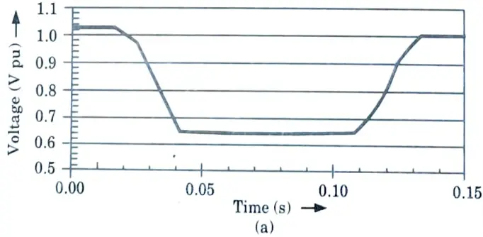
`Ans. i. Voltage sag :
- 1. A sag is a reduction in rms voltage or current of between 0.1 and 0.9 per unit at the power frequency for durations ranging from 0.5 cycle to 1 minute.
- 2. A short-duration voltage fall is referred to as sag in the power quality community.
- 3. Voltage sags are typically induced by system defects, but they can also be caused by energizing big loads or starting powerful motors.
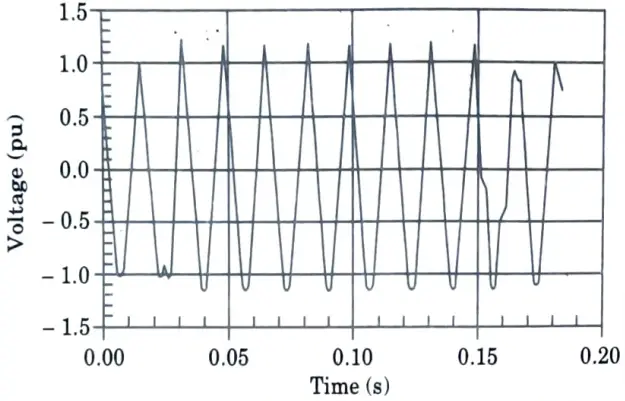
- 4. Fig.(a) shows typical voltage sag that can be associated with a single line to ground (SLG) fault on another feeder from the same substation.
- 5. An induction motor will draw 6 to 10 times its full load current start up.
- 6. If current magnitude is large relative to that available for current in the system at that point the resulting voltage sag can be significant.
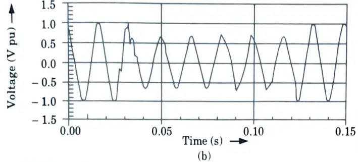
ii. Voltage interruption :
- 1. An interruption occurs when the supply voltage or load current falls below 0.1 per unit for a duration of no more than 1 minute.
- 2. Because the voltage magnitude is always less than 10% of the nominal, the interruptions are monitored by their duration.
- 3. The working time of utility protective devices determines the duration of an interruption caused by a failure in the utility system.
- 4. In most cases, instantaneous reclusion will restrict the disruption caused by a non-permanent failure to fewer than 30 cycles. Delays in shutting the protective device may result in a brief or temporary disruption.
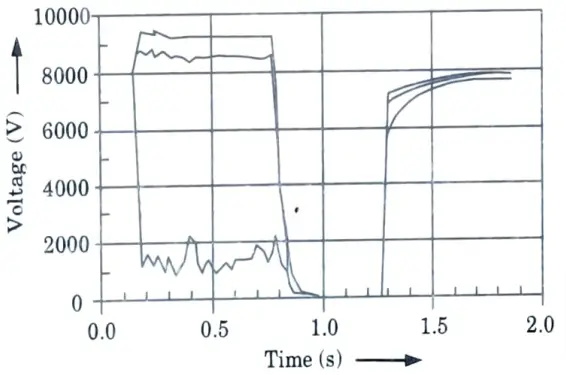
- 5. Fig. shows a momentary interruption during which voltage on one phase sags to about 20 % for about 3 cycles and then drops to zero for about 1.8 sec until the recloser closes back.
iii. Voltage swells :
- 1. A swell is defined as a rise in rms voltage or current of between 1.1 and 1.8 per unit at the power frequency over a duration of 0.5 cycle to 1 minute.
- 2. Swells, like sags, are typically associated with system fault circumstances, but they are less prevalent than voltage sags.
- 3. During a single line-to-ground (SLG) failure, a swell might occur due to a transient voltage spike on the unfaulted phases.
- 4. Swells can also be created by turning off a huge load or turning on a large capacitor bank.
- 5. Swells are characterized by their magnitude (rms value) and duration. The severity of a voltage swell during a fault condition is a function of the fault location, system impedance and grounding.
- 6. Fig. illustrates a voltage swell car sed by an SLG fault.
iv. Harmonics :Harmonics are sinusoidal voltages or currents having frequencies that are integer multiples of the frequency at which the supply system is designed to operate.
Section 4 : Sources/Causes of Voltage Sag
a. Analyze the sources/causes of voltage sag. Explain in detail.
Ans. Sources of voltage sag :
- i. Motor starting :
- 1. Motors have the unfavourable characteristic of drawing several times their entire load current upon beginning.
- 2. Because this enormous current is travelling through system impedances, it will induce a voltage drop, which may dim lights, cause contactors to fail, and damage sensitive equipment.
- 3. The condition is exacerbated by an exceptionally low initial displacement factor, which typically ranges between 15 and 30 percent.
- ii. Arc furnace :
- 1. The voltage across an electric arc is composed of three components: anode drop, cathode drop, and arc column component, totaling around 12 volts/em of arc length.
- 2. The three primary operational modes of an electric arc furnace that can cause distinct voltage disturbances on the power system are open circuit, short circuit, and normal operation.
- 3. Because of its nonlinear resistance, an arc furnace is a source of current harmonics of the second to seventh order, particularly during the meltdown stage.
- 4. Voltage variations are caused by impedance on the value of supplied harmonic currents and effective impedances at the harmonic frequencies.
b. How can we estimate the performance of voltage sag?
Ans. There are various ways to estimate the voltage sag performance:
A. Area of vulnerability :
- 1. The minimal voltage magnitude that a piece of equipment can resist or tolerate without misoperation or failure is characterised as the area of vulnerability.
- 2. This is also known as the voltage sag immunity or susceptibility limit of the equipment. The total circuit miles of exposure to faults that can cause voltage magnitudes at an end-user facility to drop below the equipment’s minimum voltage sag ride-through capability defines an area of vulnerability.
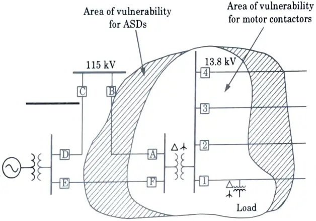
- 3. Fig. provides an example of an area of vulnerability diagram for motor contactor and variable-speed-drive loads at a distribution-served end-user facility.
- 4. Faults in both the gearbox and distribution systems will affect the loads.
- 5. The actual number of voltage sags that a facility can expect is determined by combining the area of vulnerability with the expected fault performance for this portion of the power system. The expected fault performance is usually determined from historical data.
B. Equipment sensitivity to voltage sag :
- 1. Different equipment within an end-user facility may be sensitive to voltage sags. The sensitivity of equipment to voltage sags is highly dependent on the exact load type, control settings, and applications.
- 2. As a result, it is frequently difficult to determine which properties of a given voltage sag are most likely to cause equipment to malfunction.
- 3. The duration and magnitude of the sag are the most typically used criteria.
- 4. Less typically utilised characteristics include phase shift and unbalance, missing voltage, three-phase voltage unbalance during the sag event, and the point in the wave where the sag begins and ends.
C. Transmission system sag performance evaluation :
- 1. The voltage sag performance of a specific customer facility is affected by whether it is supplied by the transmission or distribution systems.
- 2. The voltage sag performance of a customer provided by the gearbox system is solely dependent on the gearbox system fault performance.
- 3. In contrast, the voltage sag performance of a customer supplied via the distribution system is determined by the fault performance of both the gearbox and distribution systems.
- 4. Because most modern-day transmission networks are interconnected, transmission line faults and the subsequent opening of safety systems rarely create a disruption for any client.
- 5. These faults do, however, causes voltage sags. Depending on the equipment sensitivity, the unit may trip OFF, resulting in substantial monetary losses.
- 6. ASPEN (Advanced System for Power Engineering) programs can calculate the voltage throughout the system resulting from fault around the system. It is also calculate the area of vulnerability in the specific location.
D. Utility distribution system sag performance evaluation :
- 1. Faults in both the transmission and distribution systems affect customers who are supplied at distribution voltage levels.
- 2. The distribution level analysis must incorporate temporary disruptions produced by protective device activation to clear the fault.
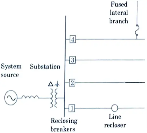
- 3. A typical distribution system with several feeders, fused branches, and safety devices is depicted in Fig. The utility protection mechanism is critical to the performance of voltage sag and temporary interruption.
- 4. The critical information needed to compute voltage sag performance can be summarized as follows:
- i. Number of feeders supplied from the substation
- ii. Average feeder length.
- iii. Average feeder reactance.
- iv. Short-circuit equivalent reactance at the substation.
Section 5 : Overvoltage Transients
a. Summarize the sources/causes of overvoltage transients.
Ans. Sources of transient overvoltage :
A. Lightning :
- 1. Lightning is a potent source of impulsive transients.
- 2. Some of the potential locations for lightning strikes, resulting in lightning currents being transmitted from the power system into loads.
- 3. The most visible conduction path happens during a direct strike to a phase wire on the transformer’s primary or secondary side.
- 4. While this might result in extremely high overvoltage, some researchers wonder whether this is the most prevalent mechanism for lightning surges to reach load facilities and cause damage.
B. Switching loads ON or OFF :
- 1. Transients can be produced by switching typical loads in a facility. When first turned ON, the majority of plant loads draw a significant amount of current.
- 2. When turned ON, transformers draw inrush currents that range between 10 and 15 times their regular full-load current. This current has a duration of 5 to 10 cycles.
- 3. Alternating current motors require beginning currents ranging from 500 to 600% of the average full-load running current.
- 4. When turned ON, fluorescent lights generate inrush currents. Transient voltages are created when a large current is pulled through the impedance of the power system, affecting electrical components sensitive to sags, subcycle oscillations, or voltage notch.
- 5. There are times when the inrush current’s harmonic frequency currents interact with the power system’s inductance and capacitance, causing resonance conditions to arise.
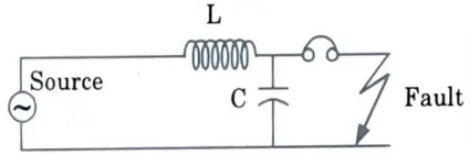
C. Interruption of fault circuits :
- 1. Large currents are generated in an electrical system during fault conditions. Overcurrent devices, such as circuit breakers or fuses, interrupt the fault currents.
- 2. Fig. depicts a simplified electrical circuit in which a circuit breaker clears an electrical fault. The letter ‘C’ reflects the capacitance of the electrical system up to the presence of the overcurrent device.
- 3. When the fault current is interrupted, an overvoltage impulse is generated in the electrical system, and the size of the voltage relies on the amount of fault current and the speed with which the fault is interrupted.
D. Capacitor bank switching :
- 1. Switching of capacitor banks in power systems is one of the more common causes of electrical transients.
- 2. During peak load hours, electrical utilities exchange capacitor banks to compensate for the load’s lagging kVAr demand.
- 3. The capacitor banks’ leading kVArs offset the load’s lagging kVAr demand, lowering the net kVA load on the circuit.
- 4. The switching of capacitor banks causes a surge of current, which is initially limited by the power system’s characteristic impedance and line resistance.
- 5. A sudden decrease in voltage is followed by a voltage surge, which decays through oscillation at a frequency dictated by the circuit’s inductance and capacitance.
- 6. The author has observed several occurrences of power system component failures and malfunctions caused by capacitor bank switching procedures.
- 7. The voltage rise caused by capacitor switching operation is typically 1.5 to 2 times the nominal voltage.
b. Summarize the methods to reduce the effects of overvoltage transients.
Ans. 1. Isolation transformers :
- i. Fig. shows a diagram of an isolation transformer used to attenuate high-frequency noise and transients as they attempt to pass from one side to the other.
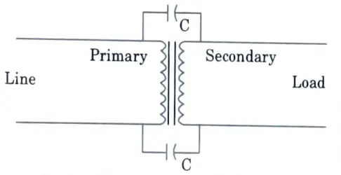
- ii. However, some common-mode and normal-mode noise can still reach the load.
- iii. An electrostatic shield, as shown in Fig. is effective in eliminating common-mode noise.
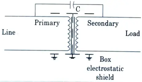
- iv. Nonetheless, due to magnetic and capacitive coupling, some normal-mode noise might still reach the load.
- v. The leakage inductance of isolation transformers is the most important feature for electrically separating the load from the system during transients.
- vi. As a result, high-frequency noise and transients are prevented from reaching the load, and any noise and transients created by the load are prevented from reaching the rest of the power system.
- vii. Voltage notching caused by power electronic switching is one example of an issue that an isolation transformer can confine to the load side.
- viii. Utility system capacitor-switching and lightning transients can be dampened, thereby avoiding.
- ix. Another application for isolation transformers is the ability to define a new ground reference or separately derived system. This new neutral-to-ground bond restricts neutral-to-ground voltages near critical equipment.
2. Surge arresters:
- i. A surge arrester is a device that protects electrical equipment from surges induced by external (lightning) or internal (switching) occurrences.
- ii. A surge arrester is connected to the conductor just before it enters the equipment to protect it from transients on an attached conductor.
- iii. The surge arrester is also grounded and works by redirecting energy from an overvoltage transient to ground.
3. Crowbar devices :
- i. Crowbar devices are typically open devices that conduct under transient overvoltages. These devices are often made with a gap filled with air or a specific gas.
- ii. When a sufficiently enough overvoltage transient arises, the gap arcs over. When the gap arcs, power frequency current, also known as “follow current,” continues to flow in the gap until next current zero.
4. Clamping devices :
- i. Clamping devices for alternating current circuits are typically non-linear resistors (varistors) that conduct very low current until an overvoltage arises.
- ii. They then begin to conduct heavily, and their impedance reduces rapidly as the voltage increases. To restrict the voltage rise caused by a surge, these devices effectively conduct increasing amounts of current (and energy).
Section 6 : Series Compensation
a. Summarize the concept of series compensation. Explain with neat diagram.
Ans. Concept of series compensation :
- 1. Series compensation is a technique for increasing system voltage by connecting a capacitor in parallel with the transmission line.
- 2. In other words, in series compensation, reactive power is added in series with the transmission line to improve the system’s impedance.
- 3. It increases the line’s power transfer capabilities. It is commonly found in extra and ultra high voltage lines.
Explanation with diagram :
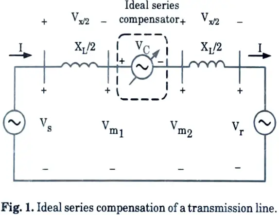
- 1. An ideal series compensator, represented by the voltage source VC, is connected in the middle of the transmission line as, shown in Fig. 1. The current flowing through the transmission line is given by :
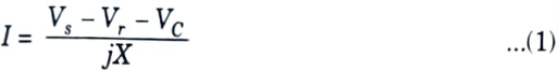
3. If the series applied voltage VC is in quadrature with respect to the line current, the series compensator cannot supply or absorb active power ie., the power at the source VC terminal can be only reactive. This means that capacitive and inductive equivalent impedance may replace the voltage source VC. The transmission line equivalent impedance is given by :
Xeq = X – Xcomp = X(1 – r) …(2)
where, r = Xcomp /X
current through the line is given by :
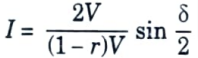
4. Active power flowing through the transmission line is given as :
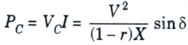
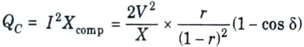
5. The reactive power QC, at the source VC terminal is given by :
b. Summarize the concept of shunt compensation. Explain with neat diagram.
Ans. Concept of shunt compensation :
- 1. FACTS are connected in parallel with the power system transmission line in shunt compensation. It functions as a variable current source.
- 2. By adjusting the shunt impedance, a reactive current is injected into the line to maintain a constant voltage magnitude.
- 3. As a result, the transmittable active power is raised, but the reactive power demand rises.
Explanation with diagram :
- 1. An ideal shunt compensator is connected at the mid-point of the transmission line as shown in the Fig. 2.

2. The compensator voltage that is in phase with the midpoint voltage Vm has a magnitude V identical to that of the sending and receiving end voltages that is Vm = Vs = Vr = V.
3. An ideal compensator is lossless i.e., the active power is the same at the sending end, midpoint and receiving end :
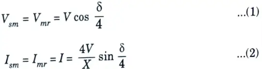
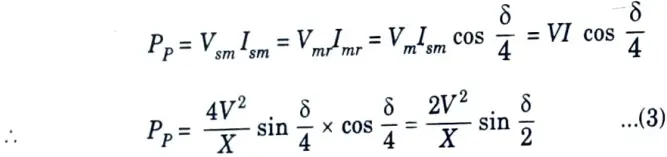
Using eg. (1) and (2) we have; the transmitted active power Pp as :
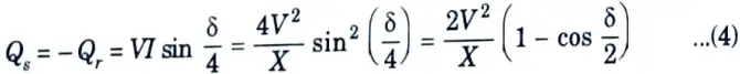
4. The reactive power QS at the sending end, which is equal and opposite to that at the receiving end Qr is given by :
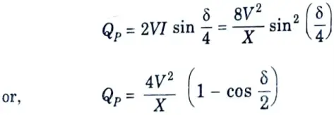
5. The reactive power Qp supplied by the shunt compensation is given by :
Section 7 : Harmonics Mitigation Techniques
a. Discuss the effects of harmonics on transformers and cables.
Ans. A. Effects of harmonics on transformer :
- 1. At fundamental frequency, transformers are intended to deliver the required power to the associated loads with minimal losses.
- 2. Harmonic distortion of current, in particular, as well as voltage, will greatly contribute to additional heating.
- 3. The RMS current of the transformer is greater than its capacity due to harmonics.
- 4. Eddy current and core losses are increased due to harmonics in the transformer.
B. Effects of harmonics on cables :
- 1. I2R losses are caused by current passing across a cable. Further losses are introduced when the load current contains harmonic content.
- 2. To make matters worse, the effective resistance of the cable increases with frequency due to the skin effect.
- 3. The skin effect is caused by unequal flux connectivity across the conductor’s cross section, causing AC currents to flow only on the conductor’s outer periphery.
- 4. The capacity of a cable to carry nonlinear loads may be determined as follows :
- i. The skin effect factor is calculated first. The skin effect factor depends on the skin depth, which is an indicator oi the penetration of the current in a conductor.
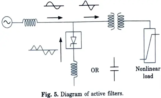
- ii. Skin depth (δ) is inversely proportional to the square root of the frequency,
where S = A proportionality constant based on the physical characteristics of the cable and its magnetic permeability
f = Frequency of the current.
iii. If Rdc is the DC resistance of the cable, then the AC resistance at frequency f,
(Rf) = k x Rdc
where, K is a constant.
b. Categorize the different harmonics mitigation techniques with diagrams.
Ans. Different harmonics mitigation techniques :
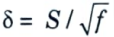
a. In-line reactors or chokes :
- 1. A relatively tiny reactor, or choke, introduced at the line input side of the drive, is a straightforward approach for controlling harmonic distortion created by changeable speed drives. This is very useful for PWM drives.
- 2. Inductance slows the pace at which the capacitor on the DC bus can be charged, forcing the drive to draw current for a longer length of time. The end result is a lower-magnitude current with far less harmonic content that nonetheless delivers the same energy.
b. Zig-zag transformers :
- 1. In commercial facilities, zig-zag transformers are frequently used to control zero-sequence harmonic components. A zig-zag transformer filters zero-sequence current by providing a low-impedance path to neutral.
- 2. By creating a shorter channel for the current, this minimises the amount of current that flows in the neutral back towards the supply.
- 3. For the transformer to be effective, it must be situated near the load on the circuit being protected.
- 4. As a result, the zigzag transformer can almost always lower zero-sequence harmonic neutral currents to tolerable values.
c. Active filters :
- 1. Active filters are relatively new types of harmonic elimination devices. They are substantially more expensive than passive filters since they are based on complex power electronics.
- 2. They do, however, have the distinct advantage of not resonating with the system. Active filters can operate independently of the impedance characteristics of the system.
- 3. As a result, they can be employed in extremely tough situations where passive filters cannot operate well due to parallel resonance issues.
Diagram of In-line reactor :
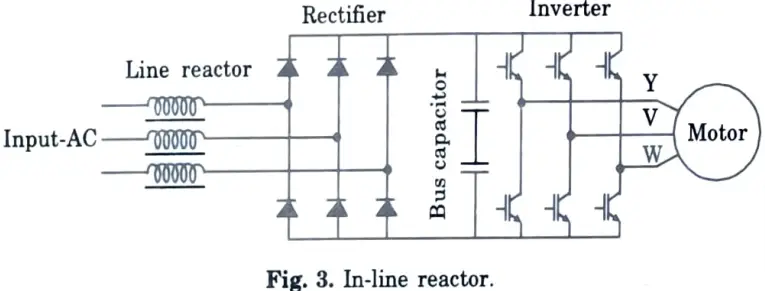
Diagram of Zig-zag transformer :
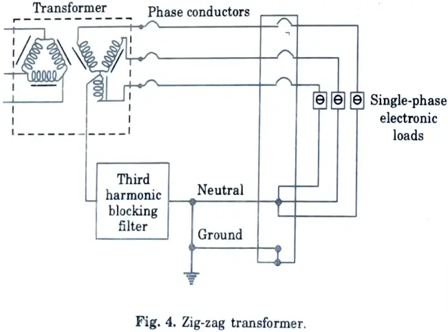
Diagram of active filters :
2 thoughts on “Power Quality and FACTS: Last year Question Paper Questions with Answer”